engine oil CHRYSLER VOYAGER 2001 Service Manual
[x] Cancel search | Manufacturer: CHRYSLER, Model Year: 2001, Model line: VOYAGER, Model: CHRYSLER VOYAGER 2001Pages: 4284, PDF Size: 83.53 MB
Page 4229 of 4284

TEST ACTION APPLICABILITY
2 The Transmission Fluid temperature must be above 21É C or 70É F prior to checking
fluid level. Adjusting fluid level on a cold transmission will result in an overfilled
transmission.
Check the Transmission Fluid Level per the Service Information.
Is the Transmission Fluid Level at the proper level?All
Ye s®Go To 3
No®If the Transmission Fluid is low, repair any Transmission Fluid
leak as necessary and adjust the Transmission Fluid Level in
accordance with the Service Information.
Perform 41TE TRANSMISSION VERIFICATION TEST - VER 1.
3 Place the gear selector in park.
Start the engine.
The Transmission must be at operating temperature prior to checking pressure. A
cold Transmission will give higher readings.
Place the Transmission in Reverse.
With the DRBIIIt, observe the Transmission Pressure Switch states.
Are any of the Pressure Switches closed?All
Ye s®Go To 4
No®Go To 6
4 The conditions necessary to set this DTC are not present at this time.
Test drive the vehicle. Allow the Transmission to shift through all gears and ranges.
Did you experience any Delayed Engagement and/ or No Drive condition?All
Ye s®Go To 6
No®Go To 5
5 The conditions necessary to set this DTC are not present at this time.
Using the schematics as a guide, inspect the wiring and connectors specific to this
circuit.
Wiggle the wiring while checking for shorts and open circuits.
Were there any problems found?All
Ye s®Repair as necessary.
Perform 41TE TRANSMISSION VERIFICATION TEST - VER 1.
No®Test Complete.
6 Remove and inspect the Transmission Oil Pan and Transmission Oil Filter per the
Service Information.
Does the Transmission Oil Pan contain excessive debris and/or is the Oil Filter
plugged?All
Ye s®Repair the cause of plugged Transmission Oil Filter. Refer to the
Service Information for repair procedures.
Perform 41TE TRANSMISSION VERIFICATION TEST - VER 1.
No®Go To 7
7 With the DRBIIIt, perform a Shift Lever Position test. Follow the instructions on the
DRBIIIt.
Did the Shift Lever Position Test pass?All
Ye s®Go To 8
No®Refer to symptom list and perform test for DTC P0705.
Perform 41TE TRANSMISSION VERIFICATION TEST - VER 1.
125
TRANSMISSION
P1791-LOSS OF PRIME ÐContinued
Page 4245 of 4284
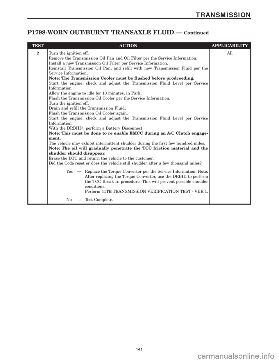
TEST ACTION APPLICABILITY
2 Turn the ignition off.
Remove the Transmission Oil Pan and Oil Filter per the Service Information.
Install a new Transmission Oil Filter per Service Information.
Reinstall Transmission Oil Pan, and refill with new Transmission Fluid per the
Service Information.
Note: The Transmission Cooler must be flushed before prodceeding.
Start the engine, check and adjust the Transmission Fluid Level per Service
Information.
Allow the engine to idle for 10 minutes, in Park.
Flush the Transmission Oil Cooler per the Service Information.
Turn the ignition off.
Drain and refill the Transmission Fluid.
Flush the Transmission Oil Cooler again.
Start the engine, check and adjust the Transmission Fluid Level per Service
Information.
With the DRBIIIt, perform a Battery Disconnect.
Note: This must be done to re enable EMCC during an A/C Clutch engage-
ment.
The vehicle may exhibit intermittent shudder during the first few hundred miles.
Note: The oil will gradually penetrate the TCC friction material and the
shudder should disappear.
Erase the DTC and return the vehicle to the customer.
Did the Code reset or does the vehicle still shudder after a few thousand miles?All
Ye s®Replace the Torque Convertor per the Service Information. Note:
After replacing the Torque Convertor, use the DRBIII to perform
the TCC Break In procedure. This will prevent possible shudder
conditions.
Perform 41TE TRANSMISSION VERIFICATION TEST - VER 1.
No®Test Complete.
141
TRANSMISSION
P1798-WORN OUT/BURNT TRANSAXLE FLUID ÐContinued
Page 4246 of 4284
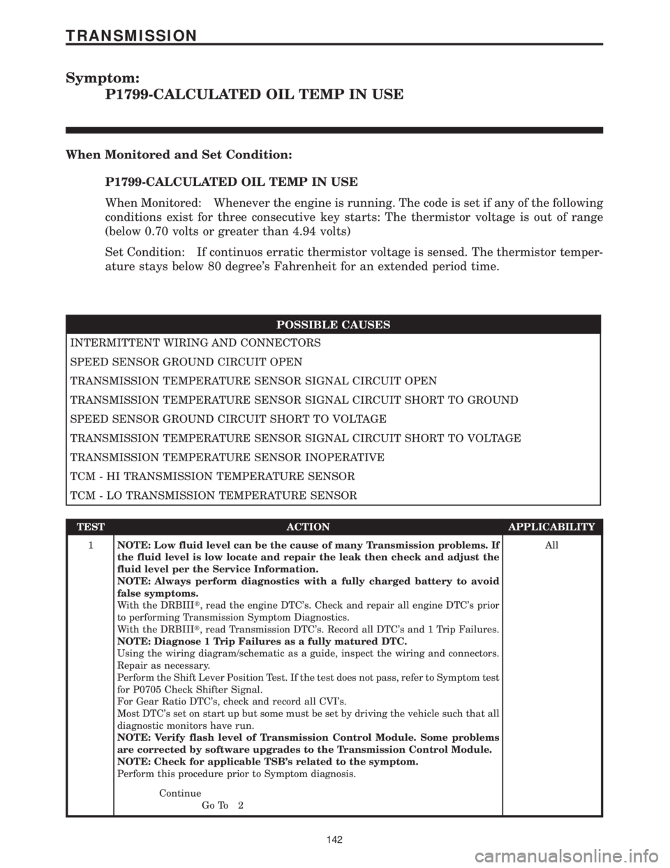
Symptom:
P1799-CALCULATED OIL TEMP IN USE
When Monitored and Set Condition:
P1799-CALCULATED OIL TEMP IN USE
When Monitored: Whenever the engine is running. The code is set if any of the following
conditions exist for three consecutive key starts: The thermistor voltage is out of range
(below 0.70 volts or greater than 4.94 volts)
Set Condition: If continuos erratic thermistor voltage is sensed. The thermistor temper-
ature stays below 80 degree's Fahrenheit for an extended period time.
POSSIBLE CAUSES
INTERMITTENT WIRING AND CONNECTORS
SPEED SENSOR GROUND CIRCUIT OPEN
TRANSMISSION TEMPERATURE SENSOR SIGNAL CIRCUIT OPEN
TRANSMISSION TEMPERATURE SENSOR SIGNAL CIRCUIT SHORT TO GROUND
SPEED SENSOR GROUND CIRCUIT SHORT TO VOLTAGE
TRANSMISSION TEMPERATURE SENSOR SIGNAL CIRCUIT SHORT TO VOLTAGE
TRANSMISSION TEMPERATURE SENSOR INOPERATIVE
TCM - HI TRANSMISSION TEMPERATURE SENSOR
TCM - LO TRANSMISSION TEMPERATURE SENSOR
TEST ACTION APPLICABILITY
1NOTE: Low fluid level can be the cause of many Transmission problems. If
the fluid level is low locate and repair the leak then check and adjust the
fluid level per the Service Information.
NOTE: Always perform diagnostics with a fully charged battery to avoid
false symptoms.
With the DRBIIIt, read the engine DTC's. Check and repair all engine DTC's prior
to performing Transmission Symptom Diagnostics.
With the DRBIIIt, read Transmission DTC's. Record all DTC's and 1 Trip Failures.
NOTE: Diagnose 1 Trip Failures as a fully matured DTC.
Using the wiring diagram/schematic as a guide, inspect the wiring and connectors.
Repair as necessary.
Perform the Shift Lever Position Test. If the test does not pass, refer to Symptom test
for P0705 Check Shifter Signal.
For Gear Ratio DTC's, check and record all CVI's.
Most DTC's set on start up but some must be set by driving the vehicle such that all
diagnostic monitors have run.
NOTE: Verify flash level of Transmission Control Module. Some problems
are corrected by software upgrades to the Transmission Control Module.
NOTE: Check for applicable TSB's related to the symptom.
Perform this procedure prior to Symptom diagnosis.All
Continue
Go To 2
142
TRANSMISSION
Page 4247 of 4284
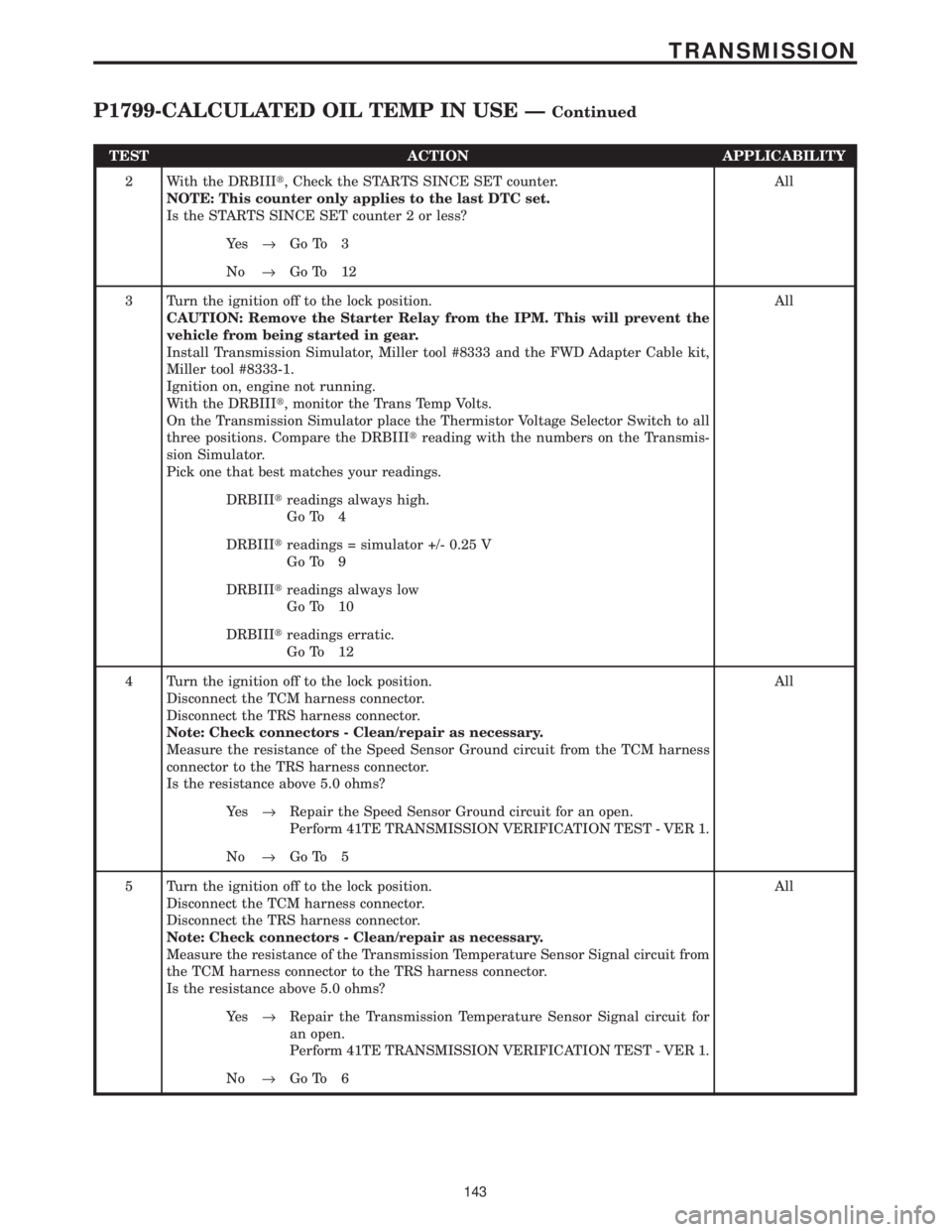
TEST ACTION APPLICABILITY
2 With the DRBIIIt, Check the STARTS SINCE SET counter.
NOTE: This counter only applies to the last DTC set.
Is the STARTS SINCE SET counter 2 or less?All
Ye s®Go To 3
No®Go To 12
3 Turn the ignition off to the lock position.
CAUTION: Remove the Starter Relay from the IPM. This will prevent the
vehicle from being started in gear.
Install Transmission Simulator, Miller tool #8333 and the FWD Adapter Cable kit,
Miller tool #8333-1.
Ignition on, engine not running.
With the DRBIIIt, monitor the Trans Temp Volts.
On the Transmission Simulator place the Thermistor Voltage Selector Switch to all
three positions. Compare the DRBIIItreading with the numbers on the Transmis-
sion Simulator.
Pick one that best matches your readings.All
DRBIIItreadings always high.
Go To 4
DRBIIItreadings = simulator +/- 0.25 V
Go To 9
DRBIIItreadings always low
Go To 10
DRBIIItreadings erratic.
Go To 12
4 Turn the ignition off to the lock position.
Disconnect the TCM harness connector.
Disconnect the TRS harness connector.
Note: Check connectors - Clean/repair as necessary.
Measure the resistance of the Speed Sensor Ground circuit from the TCM harness
connector to the TRS harness connector.
Is the resistance above 5.0 ohms?All
Ye s®Repair the Speed Sensor Ground circuit for an open.
Perform 41TE TRANSMISSION VERIFICATION TEST - VER 1.
No®Go To 5
5 Turn the ignition off to the lock position.
Disconnect the TCM harness connector.
Disconnect the TRS harness connector.
Note: Check connectors - Clean/repair as necessary.
Measure the resistance of the Transmission Temperature Sensor Signal circuit from
the TCM harness connector to the TRS harness connector.
Is the resistance above 5.0 ohms?All
Ye s®Repair the Transmission Temperature Sensor Signal circuit for
an open.
Perform 41TE TRANSMISSION VERIFICATION TEST - VER 1.
No®Go To 6
143
TRANSMISSION
P1799-CALCULATED OIL TEMP IN USE ÐContinued
Page 4248 of 4284
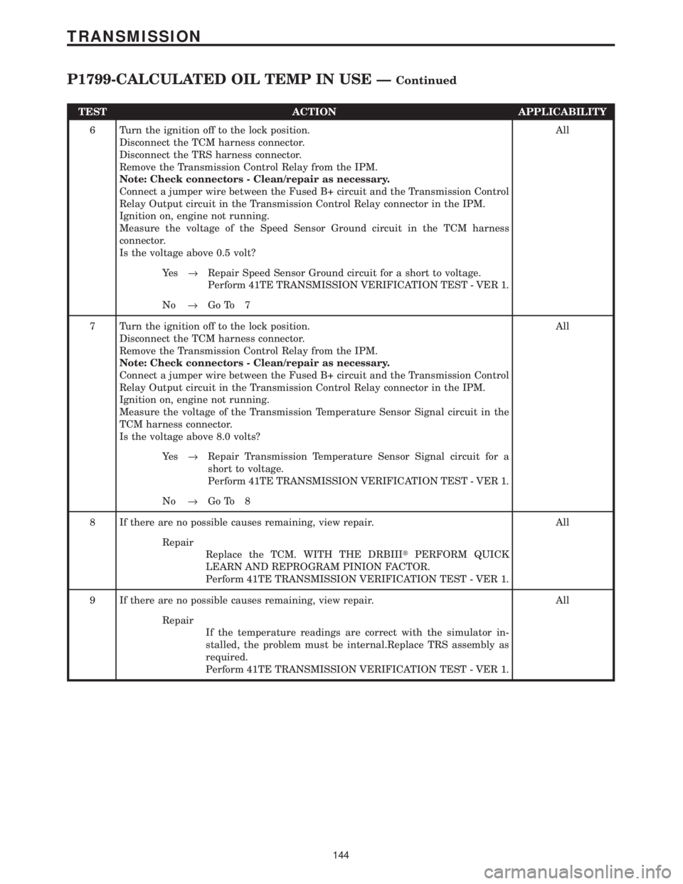
TEST ACTION APPLICABILITY
6 Turn the ignition off to the lock position.
Disconnect the TCM harness connector.
Disconnect the TRS harness connector.
Remove the Transmission Control Relay from the IPM.
Note: Check connectors - Clean/repair as necessary.
Connect a jumper wire between the Fused B+ circuit and the Transmission Control
Relay Output circuit in the Transmission Control Relay connector in the IPM.
Ignition on, engine not running.
Measure the voltage of the Speed Sensor Ground circuit in the TCM harness
connector.
Is the voltage above 0.5 volt?All
Ye s®Repair Speed Sensor Ground circuit for a short to voltage.
Perform 41TE TRANSMISSION VERIFICATION TEST - VER 1.
No®Go To 7
7 Turn the ignition off to the lock position.
Disconnect the TCM harness connector.
Remove the Transmission Control Relay from the IPM.
Note: Check connectors - Clean/repair as necessary.
Connect a jumper wire between the Fused B+ circuit and the Transmission Control
Relay Output circuit in the Transmission Control Relay connector in the IPM.
Ignition on, engine not running.
Measure the voltage of the Transmission Temperature Sensor Signal circuit in the
TCM harness connector.
Is the voltage above 8.0 volts?All
Ye s®Repair Transmission Temperature Sensor Signal circuit for a
short to voltage.
Perform 41TE TRANSMISSION VERIFICATION TEST - VER 1.
No®Go To 8
8 If there are no possible causes remaining, view repair. All
Repair
Replace the TCM. WITH THE DRBIIItPERFORM QUICK
LEARN AND REPROGRAM PINION FACTOR.
Perform 41TE TRANSMISSION VERIFICATION TEST - VER 1.
9 If there are no possible causes remaining, view repair. All
Repair
If the temperature readings are correct with the simulator in-
stalled, the problem must be internal.Replace TRS assembly as
required.
Perform 41TE TRANSMISSION VERIFICATION TEST - VER 1.
144
TRANSMISSION
P1799-CALCULATED OIL TEMP IN USE ÐContinued
Page 4258 of 4284
Symptom:
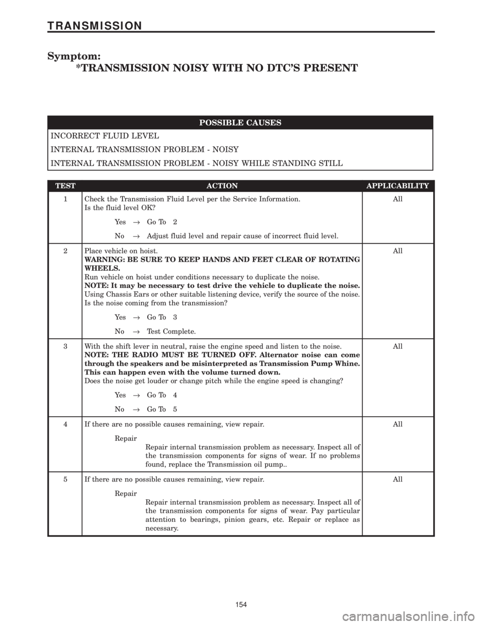
*TRANSMISSION NOISY WITH NO DTC'S PRESENT
POSSIBLE CAUSES
INCORRECT FLUID LEVEL
INTERNAL TRANSMISSION PROBLEM - NOISY
INTERNAL TRANSMISSION PROBLEM - NOISY WHILE STANDING STILL
TEST ACTION APPLICABILITY
1 Check the Transmission Fluid Level per the Service Information.
Is the fluid level OK?All
Ye s®Go To 2
No®Adjust fluid level and repair cause of incorrect fluid level.
2 Place vehicle on hoist.
WARNING: BE SURE TO KEEP HANDS AND FEET CLEAR OF ROTATING
WHEELS.
Run vehicle on hoist under conditions necessary to duplicate the noise.
NOTE: It may be necessary to test drive the vehicle to duplicate the noise.
Using Chassis Ears or other suitable listening device, verify the source of the noise.
Is the noise coming from the transmission?All
Ye s®Go To 3
No®Test Complete.
3 With the shift lever in neutral, raise the engine speed and listen to the noise.
NOTE: THE RADIO MUST BE TURNED OFF. Alternator noise can come
through the speakers and be misinterpreted as Transmission Pump Whine.
This can happen even with the volume turned down.
Does the noise get louder or change pitch while the engine speed is changing?All
Ye s®Go To 4
No®Go To 5
4 If there are no possible causes remaining, view repair. All
Repair
Repair internal transmission problem as necessary. Inspect all of
the transmission components for signs of wear. If no problems
found, replace the Transmission oil pump..
5 If there are no possible causes remaining, view repair. All
Repair
Repair internal transmission problem as necessary. Inspect all of
the transmission components for signs of wear. Pay particular
attention to bearings, pinion gears, etc. Repair or replace as
necessary.
154
TRANSMISSION
Page 4275 of 4284

POWERTRAIN CONTROL MODULE C1 - GRAY/BLACK 40 WAYCAV CIRCUIT FUNCTION
1- -
2 K18 16DB/OR (3.3L/3.8L) IGNITION COIL NO. 3 DRIVER
3 K17 16DB/TN IGNITION COIL NO. 2 DRIVER
4- -
5 V32 18VT/YL SPEED CONTROL ON/OFF SWITCH SENSE
6 K342 16BR/WT AUTOMATIC SHUTDOWN RELAY OUTPUT
7 K13 16BR/LB FUEL INJECTOR NO. 3 DRIVER
8 K20 18BR/GY GENERATOR FIELD DRIVER (+)
9- -
10 Z130 18BK/BR GROUND
11 K19 16DB/DG IGNITION COIL NO. 1 DRIVER
12 G6 16VT/GY ENGINE OIL PRESSURE SWITCH SENSE
13 K11 16BR/YL FUEL INJECTOR NO. 1 DRIVER
14 K58 16BR/VT (3.3L/3.8L) FUEL INJECTOR NO. 6 DRIVER
15 K38 16BR/OR (3.3L/3.8L) FUEL INJECTOR NO. 5 DRIVER
16 K14 16BR/TN FUEL INJECTOR NO. 4 DRIVER
17 K12 16BR/DB FUEL INJECTOR NO. 2 DRIVER
18 K99 18BR/LG OXYGEN SENSOR 1/1 HEATER CONTROL
19 - -
20 F202 18PK/GY FUSED IGNITION SWITCH OUTPUT (RUN-START)
21 - -
22 - -
23 - -
24 - -
25 K42 18DB/YL KNOCK SENSOR SIGNAL
26 K2 18VT/OR ENGINE COOLANT TEMPERATURE SENSOR SIGNAL
27 K902 18BR/DG OXYGEN SENSOR GROUND
28 - -
29 - -
30 K41 18DB/LB OXYGEN SENSOR 1/1 SIGNAL
31 T752 18DG/OR DOUBLE START OVERRIDE
32 K24 18BR/LB CRANKSHAFT POSITION SENSOR SIGNAL
33 K44 18DB/GY CAMSHAFT POSITION SENSOR SIGNAL
34 - -
35 K22 18BR/OR THROTTLE POSITION SENSOR SIGNAL
36 K1 18VT/BR MANIFOLD ABSOLUTE PRESSURE SENSOR SIGNAL
37 K21 18DB/LG INTAKE AIR TEMPERATURE SIGNAL
38 - -
39 - -
40 K35 18DB/VT EGR SOLENOID CONTROL
C
O
N
N
E
C
T
O
R
P
I
N
O
U
T
S
171
CONNECTOR PINOUTS