engine CHRYSLER VOYAGER 2001 Service Manual
[x] Cancel search | Manufacturer: CHRYSLER, Model Year: 2001, Model line: VOYAGER, Model: CHRYSLER VOYAGER 2001Pages: 4284, PDF Size: 83.53 MB
Page 1895 of 4284
STARTING
TABLE OF CONTENTS
page page
STARTER MOTOR
REMOVAL...............................7INSTALLATION............................7
STARTER MOTOR
REMOVAL
(1) Disconnect the negative battery cable.
(2) Raise vehicle and support.
(3) Remove the lower engine splash shield.
(4) Remove the electrical connectors from the
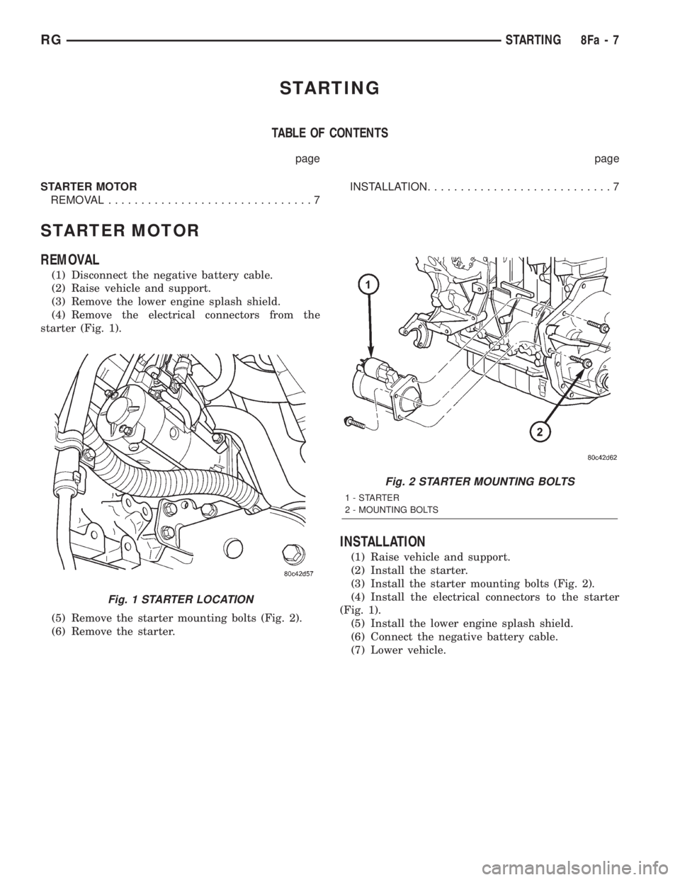
starter (Fig. 1).
(5) Remove the starter mounting bolts (Fig. 2).
(6) Remove the starter.
INSTALLATION
(1) Raise vehicle and support.
(2) Install the starter.
(3) Install the starter mounting bolts (Fig. 2).
(4) Install the electrical connectors to the starter
(Fig. 1).
(5) Install the lower engine splash shield.
(6) Connect the negative battery cable.
(7) Lower vehicle.
Fig. 1 STARTER LOCATION
Fig. 2 STARTER MOUNTING BOLTS
1-STARTER
2 - MOUNTING BOLTS
RGSTARTING8Fa-7
Page 1898 of 4284
OPERATION
The Rear Window Defogger (Fig. 1) system consists
of two vertical bus bars linked by a series of grid
lines on the inside surface of the rear window. The
electrical circuit consists of the rear defogger switch
in the HVAC control assembly and a relay with timer
switch to turn OFF the system after ten minutes.
The main feed circuit is protected by fuse 13 (40
amp) in the Power Distribution Center (PDC) which
is integrated as a unit call Integrated Power Module
(IPM). The rear defogger switch and relay also acti-
vates the heated power side view mirrors and heated
windshield wiper de-icer. The heated windshield
wiper de-icer is powered by the RUN/ACC relay in
the IPM and feed thru fuse #11 (20 amp) in the PDC.
The heated mirror circuit is protected by a non-servi-
cable Positive Temperature Coefficient (PTC) located
inside the PDC. The heated windshield wiper de-icer
circuit is protected by fuse 11 (20 amp) in the PDC.
The Heated Windshield Wiper Deicer is also acti-
vated when the DEFROST mode is selected on the
HVAC. In the DEFROST mode the rear defogger
relay/timer is bypassed, the heated windshield wiper
de-icer will stay ON until the another mode is
selected. For circuit information and component loca-
tion refer to appropriate section for Wiring Diagrams.
CAUTION:
Since grid lines can be damaged or scraped off
with sharp instruments, care should be taken in
cleaning the glass or removing foreign materials,
decals or stickers. Normal glass cleaning solvents
or hot water used with rags or toweling is recom-
mended.
DEFOGGER RELAY
DESCRIPTION
There is no heated glass relay it is integrated into
the (E.B.L) relay that is located in the IPM in the
engine compartment.
REAR WINDOW DEFOGGER
GRID
STANDARD PROCEDURE - GRID LINE
REPAIR-REAR
For Grid repair procedure for the rear window
defogger (Refer to 8 - ELECTRICAL/HEATED
GLASS/WINDSHIELD GRID - STANDARD PROCE-
DURE).
REAR WINDOW DEFOGGER
SWITCH
DESCRIPTION
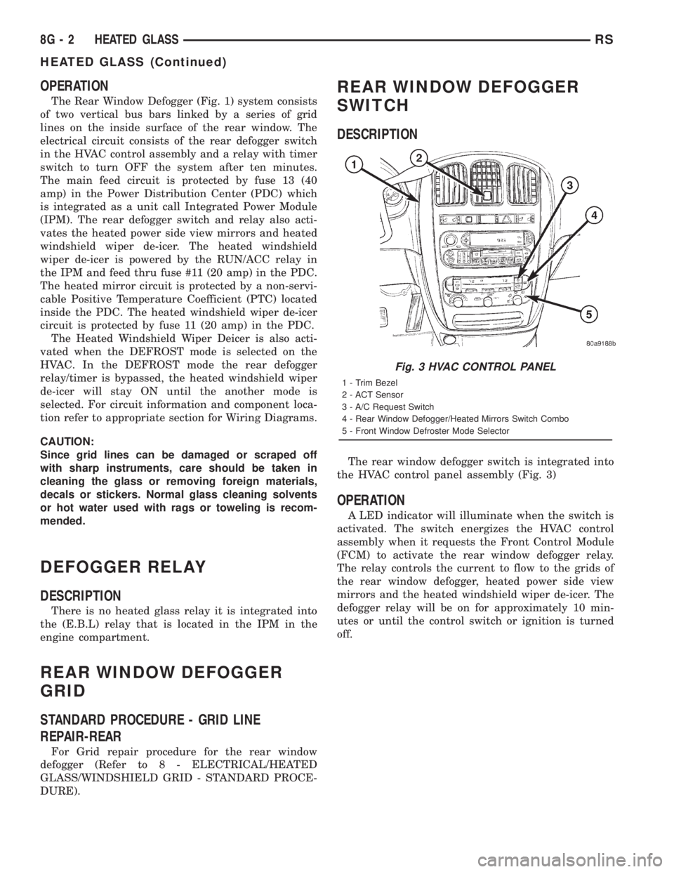
The rear window defogger switch is integrated into
the HVAC control panel assembly (Fig. 3)
OPERATION
A LED indicator will illuminate when the switch is
activated. The switch energizes the HVAC control
assembly when it requests the Front Control Module
(FCM) to activate the rear window defogger relay.
The relay controls the current to flow to the grids of
the rear window defogger, heated power side view
mirrors and the heated windshield wiper de-icer. The
defogger relay will be on for approximately 10 min-
utes or until the control switch or ignition is turned
off.
Fig. 3 HVAC CONTROL PANEL
1 - Trim Bezel
2 - ACT Sensor
3 - A/C Request Switch
4 - Rear Window Defogger/Heated Mirrors Switch Combo
5 - Front Window Defroster Mode Selector
8G - 2 HEATED GLASSRS
HEATED GLASS (Continued)
Page 1901 of 4284
HEATED MIRRORS
TABLE OF CONTENTS
page page
HEATED MIRRORS
DESCRIPTION............................5
OPERATION.............................5
DIAGNOSIS AND TESTING..................5
HEATED MIRROR TEST...................5
MIRROR SWITCH
DESCRIPTION............................5OPERATION.............................5
HEATED MIRROR GRID
STANDARD PROCEDURE...................6
HEATED MIRROR.......................6
RELAY
DESCRIPTION............................6
HEATED MIRRORS
DESCRIPTION
Heated mirrors are available on models with
Power Mirrors and Rear Window Defogger only.
OPERATION
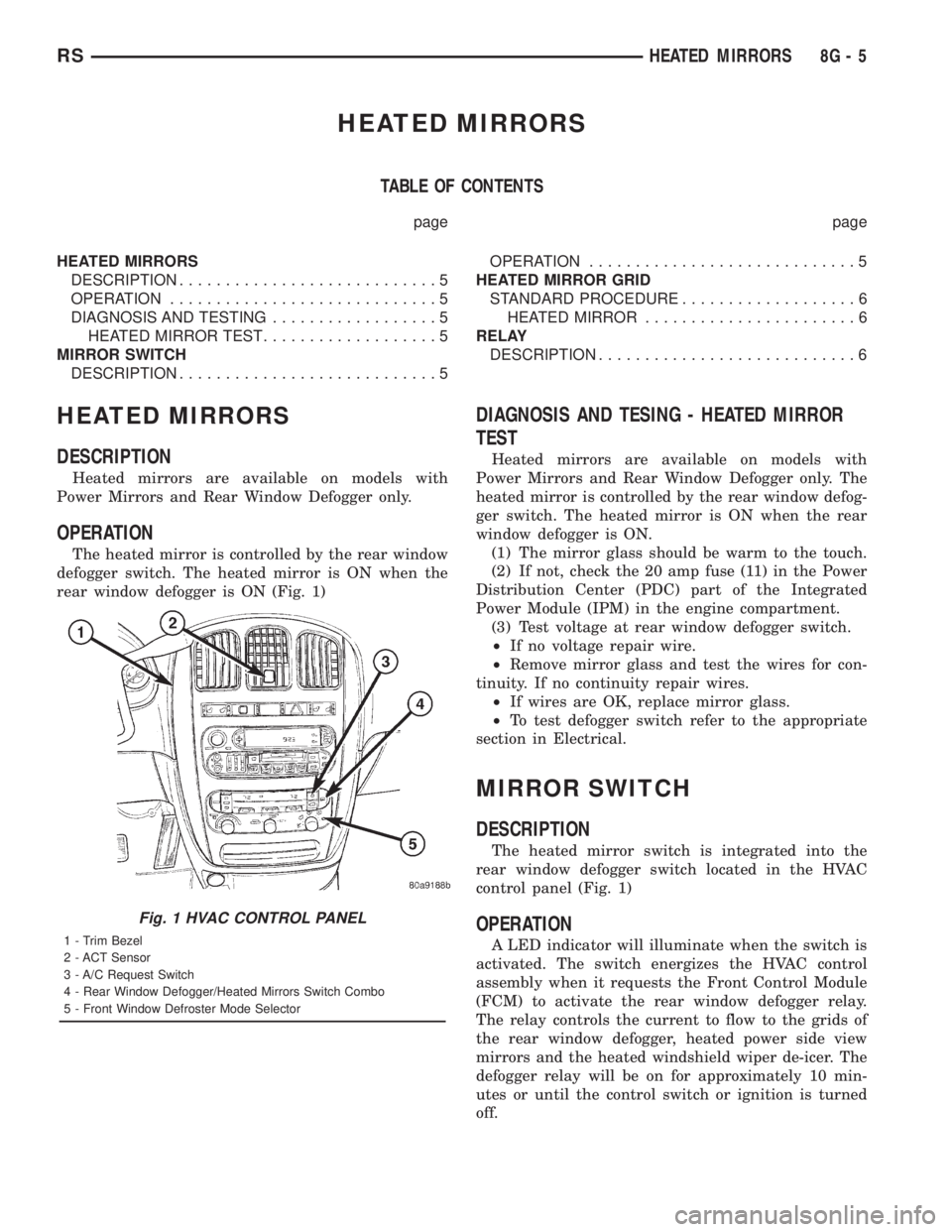
The heated mirror is controlled by the rear window
defogger switch. The heated mirror is ON when the
rear window defogger is ON (Fig. 1)
DIAGNOSIS AND TESING - HEATED MIRROR
TEST
Heated mirrors are available on models with
Power Mirrors and Rear Window Defogger only. The
heated mirror is controlled by the rear window defog-
ger switch. The heated mirror is ON when the rear
window defogger is ON.
(1) The mirror glass should be warm to the touch.
(2) If not, check the 20 amp fuse (11) in the Power
Distribution Center (PDC) part of the Integrated
Power Module (IPM) in the engine compartment.
(3) Test voltage at rear window defogger switch.
²If no voltage repair wire.
²Remove mirror glass and test the wires for con-
tinuity. If no continuity repair wires.
²If wires are OK, replace mirror glass.
²To test defogger switch refer to the appropriate
section in Electrical.
MIRROR SWITCH
DESCRIPTION
The heated mirror switch is integrated into the
rear window defogger switch located in the HVAC
control panel (Fig. 1)
OPERATION
A LED indicator will illuminate when the switch is
activated. The switch energizes the HVAC control
assembly when it requests the Front Control Module
(FCM) to activate the rear window defogger relay.
The relay controls the current to flow to the grids of
the rear window defogger, heated power side view
mirrors and the heated windshield wiper de-icer. The
defogger relay will be on for approximately 10 min-
utes or until the control switch or ignition is turned
off.
Fig. 1 HVAC CONTROL PANEL
1 - Trim Bezel
2 - ACT Sensor
3 - A/C Request Switch
4 - Rear Window Defogger/Heated Mirrors Switch Combo
5 - Front Window Defroster Mode Selector
RSHEATED MIRRORS8G-5
Page 1902 of 4284

HEATED MIRROR GRID
STANDARD PROCEDURE - HEATED MIRROR
Replacement of the mirror is necessary if the grid
is damaged and diagnostics have been performed
(Refer to 23 - BODY/EXTERIOR/SIDE VIEW MIR-
ROR - REMOVAL).
RELAY
DESCRIPTION
There is no heated mirror relay it is integrated
into the (E.B.L) relay that is located in the IPM in
the engine compartment.
8G - 6 HEATED MIRRORSRS
Page 1911 of 4284
HORN
TABLE OF CONTENTS
page page
HORN
DESCRIPTION............................1
OPERATION.............................1
DIAGNOSIS AND TESTING..................1
HORN
DIAGNOSIS AND TESTING..................3
REMOVAL...............................4INSTALLATION............................5
HORN RELAY
DIAGNOSIS AND TESTING..................5
REMOVAL...............................5
INSTALLATION............................5
HORN SWITCH
DESCRIPTION............................5
HORN
DESCRIPTION
HORN SYSTEM
WARNING:
ON VEHICLES EQUIPPED WITH AIRBAG, REFER TO
ELECTRICAL, RESTRAINTS FOR SAFETY PRECAU-
TIONS. DISCONNECT THE NEGATIVE CABLE FROM
THE BATTERY BEFORE SERVICING COMPONENTS
INVOLVING THE AIRBAG SYSTEM. ACCIDENTAL
DEPLOYMENT OF AIRBAG AND PERSONAL INJURY
CAN RESULT.
The horn circuit consists of a horn switch, clock-
spring, horn relay, horns and intelligent power mod-
ule. The horn switch is a membrane switch located in
the airbag trim cover. The horns are located forward
of the left front wheel behind the bumper fascia.
OPERATION
The horn relay plugs into the intelligent power
module which is located in the engine compartment.
For circuit information and component locations,
refer to the appropriate wiring information. The wir-
ing information includes wiring diagrams, proper
wire and connector repair procedures, details of wire
harness routing and retention, connector pin-out
information and location views for the various wire
harness connectors, splices and grounds.
The horns will not function if the switch is
ªCLOSEDº for more than 30 seconds. Once the
switch is ªOPENº, a 20±30 second delay will occur
before the horns are functional again.
DIAGNOSIS AND TESTING
Refer to Horn System Test below. If the horn does
not sound, check horn fuse located in the intelligent
power module. If the fuse is blown, replace with the
correct fuse. If the horns fail to sound and the new
fuse blows when depressing the horn switch, a short
circuit in the horn or the horn wiring between the
fuse terminal and the horn is responsible, or a defec-
tive horn switch allowed the horn to burn out is
responsible.
If the fuse is OK, test horn relay (Refer to 8 -
ELECTRICAL/HORN/HORN RELAY - DIAGNOSIS
AND TESTING).
If the relay is OK, test horn. Refer to Horn System
Test.
CAUTION:
Continuous sounding of horn may cause horn relay
to fail.
Should the horn sound continuously:
²Unplug the horn relay from intelligent power
module.
²Refer to (Refer to 8 - ELECTRICAL/HORN/
HORN RELAY - DIAGNOSIS AND TESTING).
Refer to the appropriate wiring information. The
wiring information includes wiring diagrams, proper
wire and connector repair procedures, details of wire
harness routing and retention, connector pin-out
information and location views for the various wire
harness connectors, splices and grounds.
RSHORN8H-1
Page 1917 of 4284
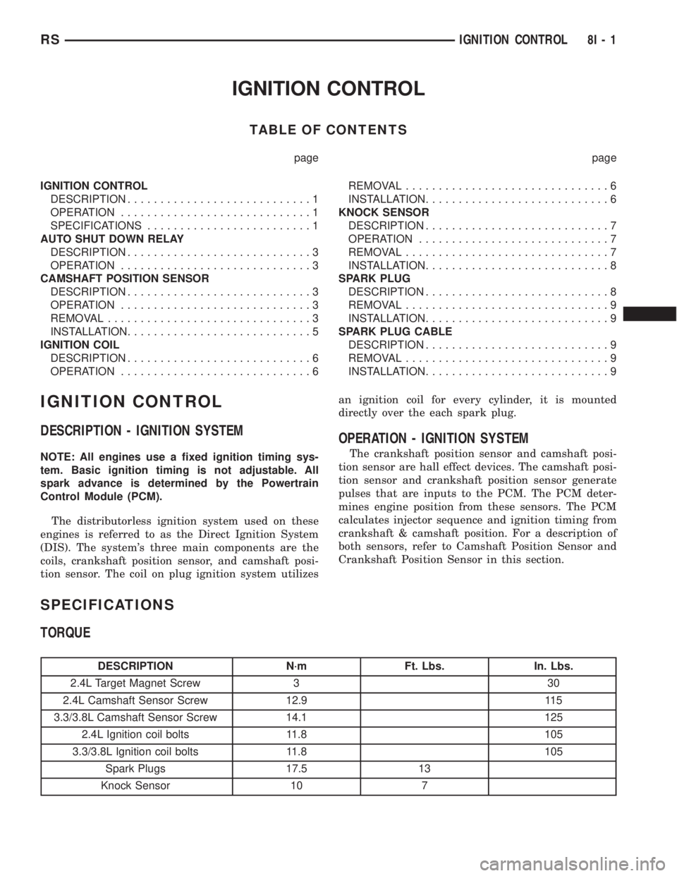
IGNITION CONTROL
TABLE OF CONTENTS
page page
IGNITION CONTROL
DESCRIPTION............................1
OPERATION.............................1
SPECIFICATIONS.........................1
AUTO SHUT DOWN RELAY
DESCRIPTION............................3
OPERATION.............................3
CAMSHAFT POSITION SENSOR
DESCRIPTION............................3
OPERATION.............................3
REMOVAL...............................3
INSTALLATION............................5
IGNITION COIL
DESCRIPTION............................6
OPERATION.............................6REMOVAL...............................6
INSTALLATION............................6
KNOCK SENSOR
DESCRIPTION............................7
OPERATION.............................7
REMOVAL...............................7
INSTALLATION............................8
SPARK PLUG
DESCRIPTION............................8
REMOVAL...............................9
INSTALLATION............................9
SPARK PLUG CABLE
DESCRIPTION............................9
REMOVAL...............................9
INSTALLATION............................9
IGNITION CONTROL
DESCRIPTION - IGNITION SYSTEM
NOTE: All engines use a fixed ignition timing sys-
tem. Basic ignition timing is not adjustable. All
spark advance is determined by the Powertrain
Control Module (PCM).
The distributorless ignition system used on these
engines is referred to as the Direct Ignition System
(DIS). The system's three main components are the
coils, crankshaft position sensor, and camshaft posi-
tion sensor. The coil on plug ignition system utilizesan ignition coil for every cylinder, it is mounted
directly over the each spark plug.
OPERATION - IGNITION SYSTEM
The crankshaft position sensor and camshaft posi-
tion sensor are hall effect devices. The camshaft posi-
tion sensor and crankshaft position sensor generate
pulses that are inputs to the PCM. The PCM deter-
mines engine position from these sensors. The PCM
calculates injector sequence and ignition timing from
crankshaft & camshaft position. For a description of
both sensors, refer to Camshaft Position Sensor and
Crankshaft Position Sensor in this section.
SPECIFICATIONS
TORQUE
DESCRIPTION N´m Ft. Lbs. In. Lbs.
2.4L Target Magnet Screw 3 30
2.4L Camshaft Sensor Screw 12.9 115
3.3/3.8L Camshaft Sensor Screw 14.1 125
2.4L Ignition coil bolts 11.8 105
3.3/3.8L Ignition coil bolts 11.8 105
Spark Plugs 17.5 13
Knock Sensor 10 7
RSIGNITION CONTROL8I-1
Page 1918 of 4284
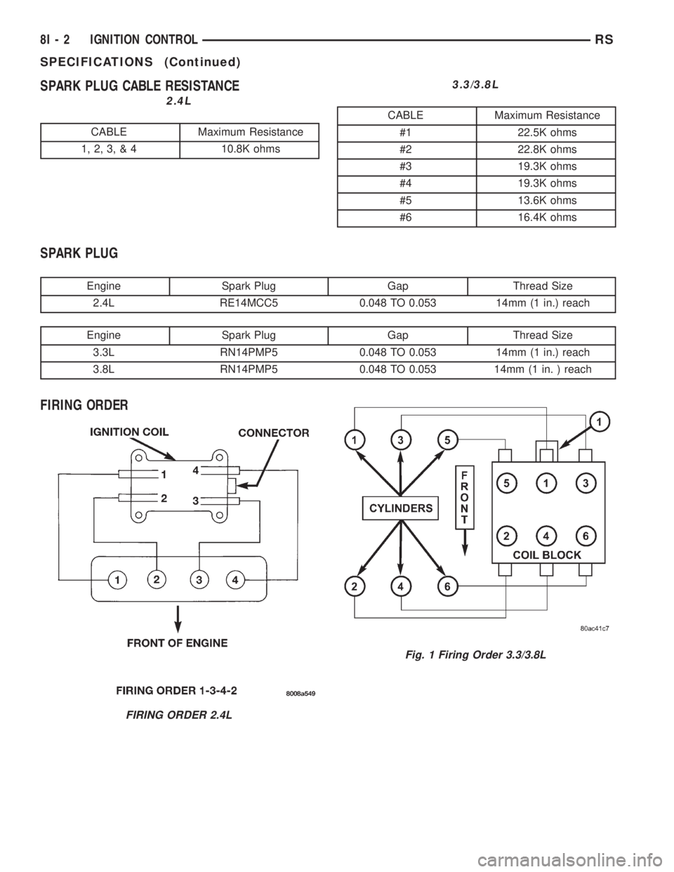
SPARK PLUG CABLE RESISTANCE
2.4L
CABLE Maximum Resistance
1, 2, 3, & 4 10.8K ohms
3.3/3.8L
CABLE Maximum Resistance
#1 22.5K ohms
#2 22.8K ohms
#3 19.3K ohms
#4 19.3K ohms
#5 13.6K ohms
#6 16.4K ohms
SPARK PLUG
Engine Spark Plug Gap Thread Size
2.4L RE14MCC5 0.048 TO 0.053 14mm (1 in.) reach
Engine Spark Plug Gap Thread Size
3.3L RN14PMP5 0.048 TO 0.053 14mm (1 in.) reach
3.8L RN14PMP5 0.048 TO 0.053 14mm (1 in. ) reach
FIRING ORDER
FIRING ORDER 2.4L
Fig. 1 Firing Order 3.3/3.8L
8I - 2 IGNITION CONTROLRS
SPECIFICATIONS (Continued)
Page 1919 of 4284
AUTO SHUT DOWN RELAY
DESCRIPTION
The relay is located in the Power Distribution Cen-
ter (PDC). For the location of the relay within the
PDC, refer to the PDC cover for location. Check elec-
trical terminals for corrosion and repair as necessary
OPERATION
The ASD sense circuit informs the PCM when the
ASD relay energizes. A 12 volt signal at this input
indicates to the PCM that the ASD has been acti-
vated. This input is used only to sense that the ASD
relay is energized.
When energized, the ASD relay supplies battery
voltage to the fuel injectors, ignition coils and the
heating element in each oxygen sensor. If the PCM
does not receive 12 volts from this input after
grounding the ASD relay, it sets a Diagnostic Trouble
Code (DTC).
When energized, the ASD relay provides power to
operate the injectors, ignition coil, generator field, O2
sensor heaters (both upstream and downstream), and
also provides a sense circuit to the PCM for diagnos-
tic purposes. The PCM energizes the ASD any time
there is a Crankshaft Position sensor signal that
exceeds a predetermined value. The ASD relay can
also be energized after the engine has been turned
off to perform an O2 sensor heater test, if vehicle is
equipped with OBD II diagnostics.
As mentioned earlier, the PCM energizes the ASD
relay during an O2 sensor heater test. This test is
performed only after the engine has been shut off.
The PCM still operates internally to perform several
checks, including monitoring the O2 sensor heaters.
CAMSHAFT POSITION
SENSOR
DESCRIPTION
The camshaft position sensorfor the 3.3/3.8L is
mounted in the front of the timing case cover (Fig. 7)
and the camshaft position sensor for the 2.4L is
mounted on the end of the cylinder head (Fig. 4).
OPERATION
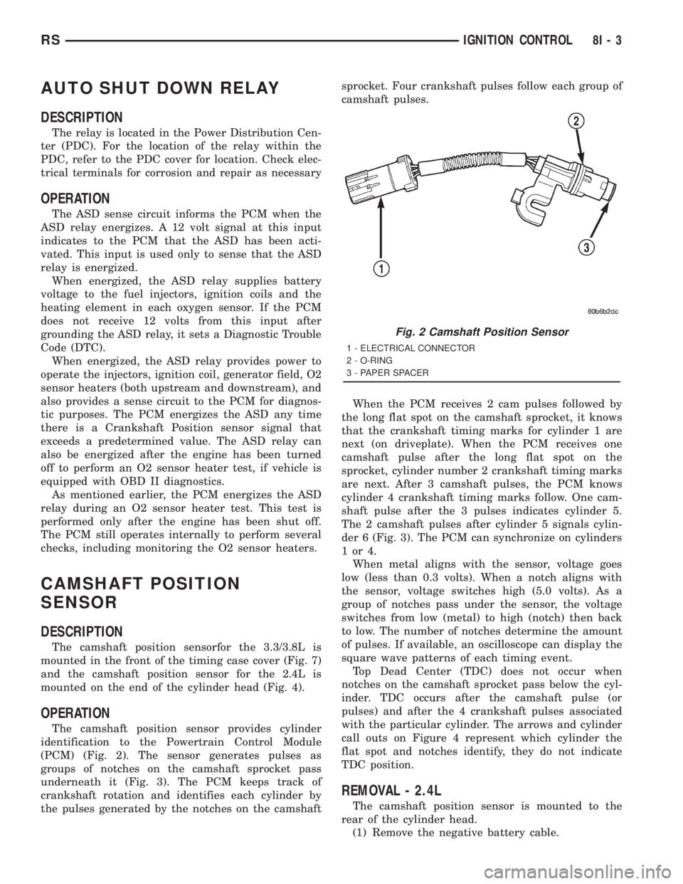
The camshaft position sensor provides cylinder
identification to the Powertrain Control Module
(PCM) (Fig. 2). The sensor generates pulses as
groups of notches on the camshaft sprocket pass
underneath it (Fig. 3). The PCM keeps track of
crankshaft rotation and identifies each cylinder by
the pulses generated by the notches on the camshaftsprocket. Four crankshaft pulses follow each group of
camshaft pulses.
When the PCM receives 2 cam pulses followed by
the long flat spot on the camshaft sprocket, it knows
that the crankshaft timing marks for cylinder 1 are
next (on driveplate). When the PCM receives one
camshaft pulse after the long flat spot on the
sprocket, cylinder number 2 crankshaft timing marks
are next. After 3 camshaft pulses, the PCM knows
cylinder 4 crankshaft timing marks follow. One cam-
shaft pulse after the 3 pulses indicates cylinder 5.
The 2 camshaft pulses after cylinder 5 signals cylin-
der 6 (Fig. 3). The PCM can synchronize on cylinders
1or4.
When metal aligns with the sensor, voltage goes
low (less than 0.3 volts). When a notch aligns with
the sensor, voltage switches high (5.0 volts). As a
group of notches pass under the sensor, the voltage
switches from low (metal) to high (notch) then back
to low. The number of notches determine the amount
of pulses. If available, an oscilloscope can display the
square wave patterns of each timing event.
Top Dead Center (TDC) does not occur when
notches on the camshaft sprocket pass below the cyl-
inder. TDC occurs after the camshaft pulse (or
pulses) and after the 4 crankshaft pulses associated
with the particular cylinder. The arrows and cylinder
call outs on Figure 4 represent which cylinder the
flat spot and notches identify, they do not indicate
TDC position.
REMOVAL - 2.4L
The camshaft position sensor is mounted to the
rear of the cylinder head.
(1) Remove the negative battery cable.
Fig. 2 Camshaft Position Sensor
1 - ELECTRICAL CONNECTOR
2 - O-RING
3 - PAPER SPACER
RSIGNITION CONTROL8I-3
Page 1921 of 4284
(4) Remove bolt holding sensor.
(5) Rotate sensor away from block.
(6) Pull sensor up out of the chain case cover.Do
not pull on the sensor lead.There is an O-ring on
the sensor case. The O-ring may make removal diffi-
cult. A light tap to top of sensor prior to removal may
reduce force needed for removal.
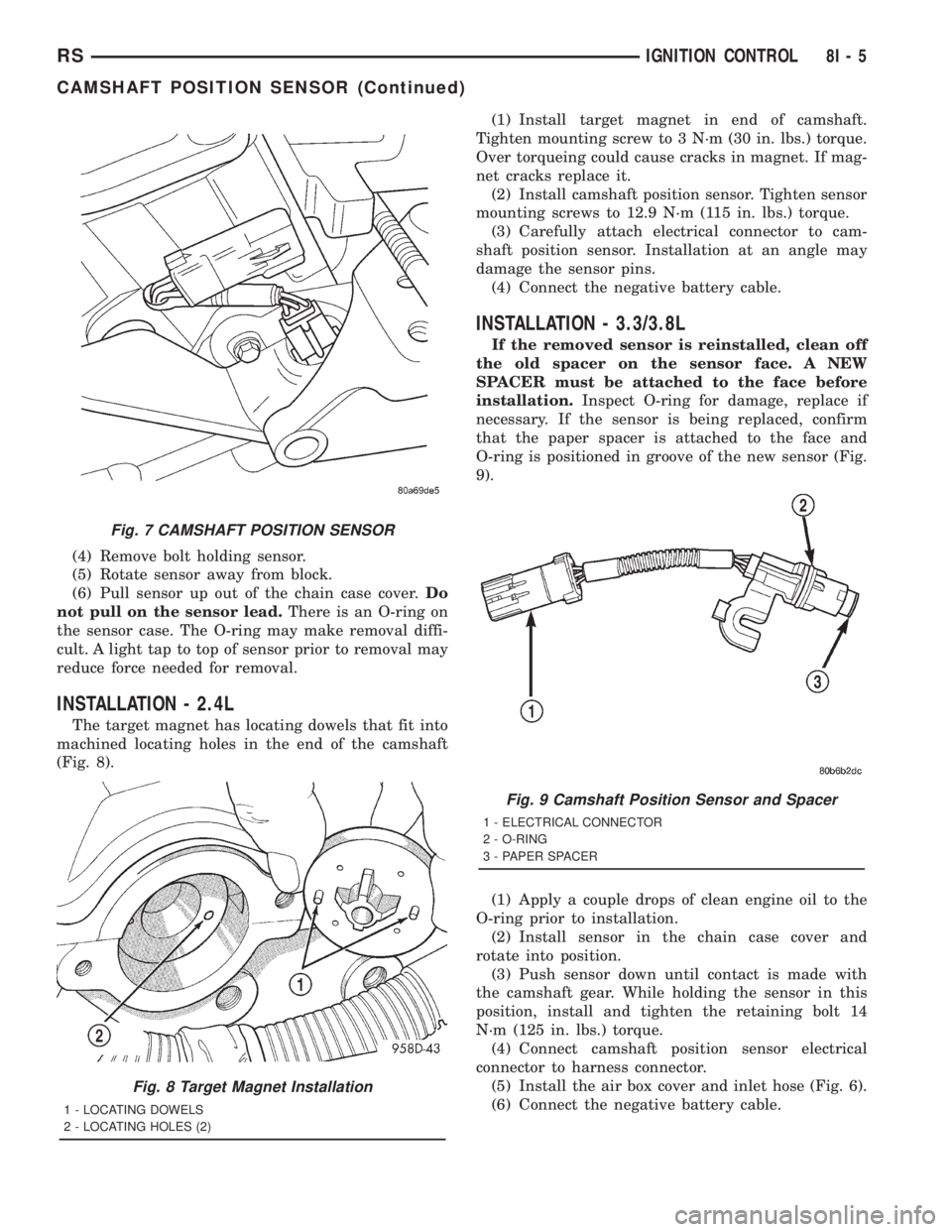
INSTALLATION - 2.4L
The target magnet has locating dowels that fit into
machined locating holes in the end of the camshaft
(Fig. 8).(1) Install target magnet in end of camshaft.
Tighten mounting screw to 3 N´m (30 in. lbs.) torque.
Over torqueing could cause cracks in magnet. If mag-
net cracks replace it.
(2) Install camshaft position sensor. Tighten sensor
mounting screws to 12.9 N´m (115 in. lbs.) torque.
(3) Carefully attach electrical connector to cam-
shaft position sensor. Installation at an angle may
damage the sensor pins.
(4) Connect the negative battery cable.
INSTALLATION - 3.3/3.8L
If the removed sensor is reinstalled, clean off
the old spacer on the sensor face. A NEW
SPACER must be attached to the face before
installation.Inspect O-ring for damage, replace if
necessary. If the sensor is being replaced, confirm
that the paper spacer is attached to the face and
O-ring is positioned in groove of the new sensor (Fig.
9).
(1) Apply a couple drops of clean engine oil to the
O-ring prior to installation.
(2) Install sensor in the chain case cover and
rotate into position.
(3) Push sensor down until contact is made with
the camshaft gear. While holding the sensor in this
position, install and tighten the retaining bolt 14
N´m (125 in. lbs.) torque.
(4) Connect camshaft position sensor electrical
connector to harness connector.
(5) Install the air box cover and inlet hose (Fig. 6).
(6) Connect the negative battery cable.
Fig. 7 CAMSHAFT POSITION SENSOR
Fig. 8 Target Magnet Installation
1 - LOCATING DOWELS
2 - LOCATING HOLES (2)
Fig. 9 Camshaft Position Sensor and Spacer
1 - ELECTRICAL CONNECTOR
2 - O-RING
3 - PAPER SPACER
RSIGNITION CONTROL8I-5
CAMSHAFT POSITION SENSOR (Continued)
Page 1923 of 4284
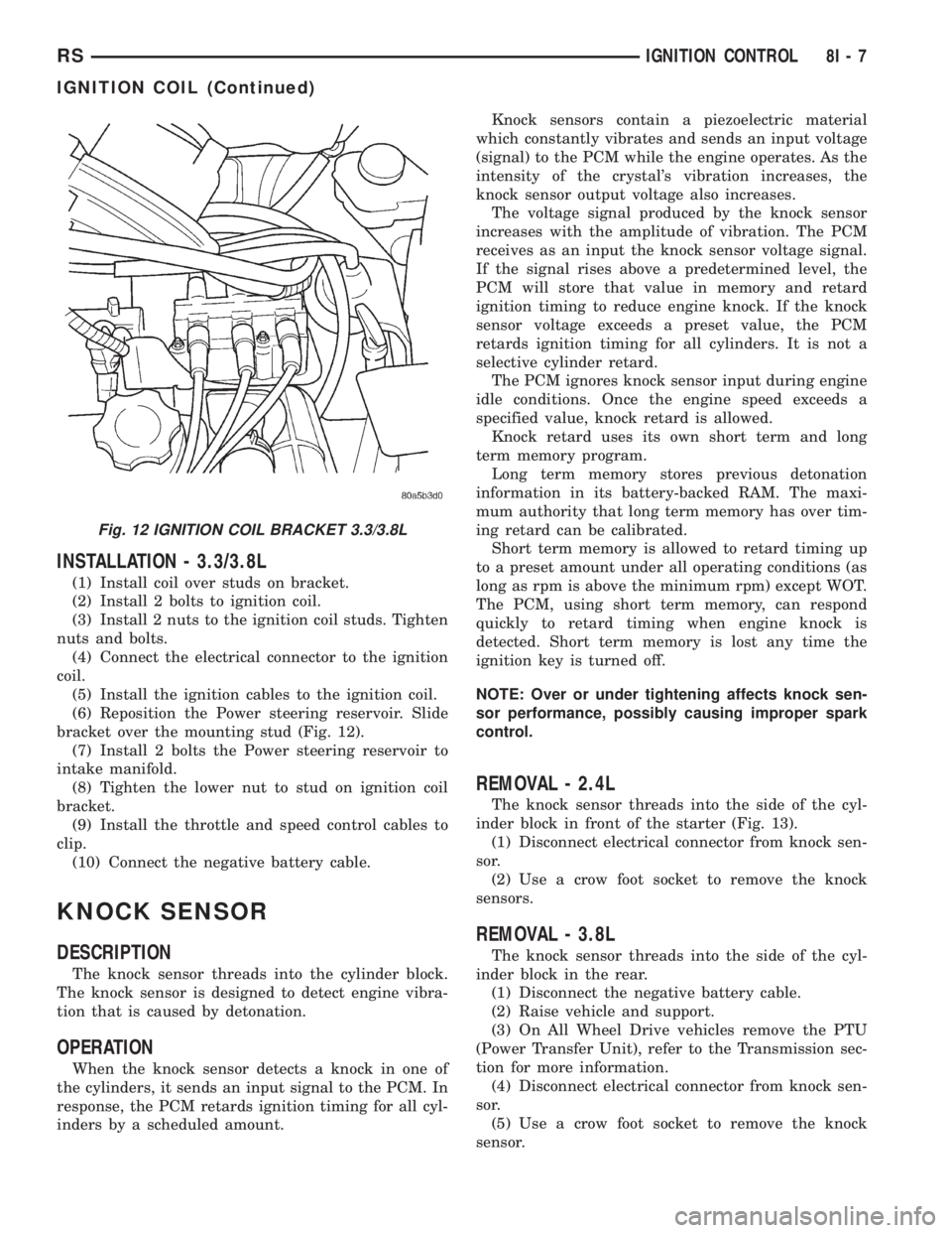
INSTALLATION - 3.3/3.8L
(1) Install coil over studs on bracket.
(2) Install 2 bolts to ignition coil.
(3) Install 2 nuts to the ignition coil studs. Tighten
nuts and bolts.
(4) Connect the electrical connector to the ignition
coil.
(5) Install the ignition cables to the ignition coil.
(6) Reposition the Power steering reservoir. Slide
bracket over the mounting stud (Fig. 12).
(7) Install 2 bolts the Power steering reservoir to
intake manifold.
(8) Tighten the lower nut to stud on ignition coil
bracket.
(9) Install the throttle and speed control cables to
clip.
(10) Connect the negative battery cable.
KNOCK SENSOR
DESCRIPTION
The knock sensor threads into the cylinder block.
The knock sensor is designed to detect engine vibra-
tion that is caused by detonation.
OPERATION
When the knock sensor detects a knock in one of
the cylinders, it sends an input signal to the PCM. In
response, the PCM retards ignition timing for all cyl-
inders by a scheduled amount.Knock sensors contain a piezoelectric material
which constantly vibrates and sends an input voltage
(signal) to the PCM while the engine operates. As the
intensity of the crystal's vibration increases, the
knock sensor output voltage also increases.
The voltage signal produced by the knock sensor
increases with the amplitude of vibration. The PCM
receives as an input the knock sensor voltage signal.
If the signal rises above a predetermined level, the
PCM will store that value in memory and retard
ignition timing to reduce engine knock. If the knock
sensor voltage exceeds a preset value, the PCM
retards ignition timing for all cylinders. It is not a
selective cylinder retard.
The PCM ignores knock sensor input during engine
idle conditions. Once the engine speed exceeds a
specified value, knock retard is allowed.
Knock retard uses its own short term and long
term memory program.
Long term memory stores previous detonation
information in its battery-backed RAM. The maxi-
mum authority that long term memory has over tim-
ing retard can be calibrated.
Short term memory is allowed to retard timing up
to a preset amount under all operating conditions (as
long as rpm is above the minimum rpm) except WOT.
The PCM, using short term memory, can respond
quickly to retard timing when engine knock is
detected. Short term memory is lost any time the
ignition key is turned off.
NOTE: Over or under tightening affects knock sen-
sor performance, possibly causing improper spark
control.
REMOVAL - 2.4L
The knock sensor threads into the side of the cyl-
inder block in front of the starter (Fig. 13).
(1) Disconnect electrical connector from knock sen-
sor.
(2) Use a crow foot socket to remove the knock
sensors.
REMOVAL - 3.8L
The knock sensor threads into the side of the cyl-
inder block in the rear.
(1) Disconnect the negative battery cable.
(2) Raise vehicle and support.
(3) On All Wheel Drive vehicles remove the PTU
(Power Transfer Unit), refer to the Transmission sec-
tion for more information.
(4) Disconnect electrical connector from knock sen-
sor.
(5) Use a crow foot socket to remove the knock
sensor.
Fig. 12 IGNITION COIL BRACKET 3.3/3.8L
RSIGNITION CONTROL8I-7
IGNITION COIL (Continued)