relay CHRYSLER VOYAGER 2001 Service Manual
[x] Cancel search | Manufacturer: CHRYSLER, Model Year: 2001, Model line: VOYAGER, Model: CHRYSLER VOYAGER 2001Pages: 4284, PDF Size: 83.53 MB
Page 4222 of 4284

Symptom:
P1788-2/4 HYDRAULIC PRESSURE TEST FAILURE
When Monitored and Set Condition:
P1788-2/4 HYDRAULIC PRESSURE TEST FAILURE
When Monitored: In any forward gear with engine speed above 1000 RPM shortly after
a shift and every minute thereafter.
Set Condition: After a shift into a forward gear, with engine speed > 1000 RPM, the TCM
momentarily turns on element pressure to the clutch ckts that don't have pressure to
identify the correct pressure sw closes. If the pressure sw does not close 2 times the code
sets.
POSSIBLE CAUSES
LOSS OF PRIME P1791 PRESENT
RELATED DTC'S PRESENT
TRANSMISSION FLUID LEVEL
INTERMITTENT WIRING AND CONNECTORS
TRANSMISSION CONTROL RELAY OUTPUT CIRCUIT OPEN
2/4 PRESSURE SWITCH SENSE CIRCUIT OPEN
2/4 PRESSURE SWITCH SENSE CIRCUIT SHORT TO GROUND
2/4 PRESSURE SWITCH SENSE CIRCUIT SHORT TO VOLTAGE
INTERNAL TRANSMISSION
TCM - 2/4 HYDRAULIC PRESSURE
11 8
TRANSMISSION
Page 4224 of 4284

TEST ACTION APPLICABILITY
5 Turn the ignition off to the lock position.
CAUTION: Remove the Starter Relay from the IPM. This will prevent the
vehicle from being started in gear.
Install Transmission Simulator, Miller tool #8333 and the FWD Adapter Cable kit,
Miller tool #8333-1.
Note: Check connectors - Clean/repair as necessary.
Ignition on, engine not running.
On the Transmission Simulator select 2/4 on the Pressure Switch selector switch.
With the DRBIIIt, monitor the 2/4 Pressure Switch state while pressing the Pressure
Switch Test button on the Transmission Simulator.
Wiggle the wiring leading to the TCM while pressing the button.
Did the 2-4 Pressure Switch state change to closed and remain closed while wiggling
the wires?All
Ye s®Go To 6
No®Go To 8
6 The Transmission must be above 70 degree F. prior to checking fluid level. Adjusting
fluid level on a cold transmission will result in an overfilled Transmission.
Check the Transmission Fluid Level per the Service Information.
Is the Transmission Fluid Level at the proper level?All
Ye s®Go To 7
No®Adjust fluid level. Repair cause of incorrect fluid level.
Perform 41TE TRANSMISSION VERIFICATION TEST - VER 1.
7 If there are no possible causes remaining, view repair. All
Repair
Disassemble and inspect the Valve Body per service information
and repair or replace as necessary. If there are no problems found
in the Valve Body, replace the Transmission Solenoid/Pressure
Switch Assembly per the Service Information,
Perform 41TE TRANSMISSION VERIFICATION TEST - VER 1.
8 Turn the ignition off to the lock position.
Disconnect the Transmission Solenoid/Pressure Switch Assembly harness connector.
Remove the Transmission Control Relay from the IPM.
Note: Check connectors - Clean/repair as necessary.
Connect a jumper wire between the Fused B+ circuit and Transmission Control Relay
Output circuit in the Transmission Control Relay connector in the IPM.
Using a 12-volt test light connected to ground, check the Transmission Control Relay
Output circuit in the Solenoid/Pressure Switch Assembly harness connector.
NOTE: The test light must illuminate brightly. Compare the brightness to
that of a direct connection to the battery.
Does the test light illuminate brightly?All
Ye s®Go To 9
No®Repair the Transmission Control Relay Output circuit for an open
or high resistance. If the fuse is open make sure to check for a
short to ground.
Perform 41TE TRANSMISSION VERIFICATION TEST - VER 1.
120
TRANSMISSION
P1788-2/4 HYDRAULIC PRESSURE TEST FAILURE ÐContinued
Page 4225 of 4284

TEST ACTION APPLICABILITY
9 Turn the ignition off to the lock position.
Disconnect the TCM harness connector.
Disconnect the Transmission Solenoid/Pressure Switch Assembly harness connector.
Note: Check connectors - Clean/repair as necessary.
Measure the resistance of the 2/4 Pressure Switch Sense circuit from the TCM
harness connector to the Transmission Solenoid/Pressure Switch Assembly harness
connector.
Is the resistance above 5.0 ohms?All
Ye s®Repair the 2/4 Pressure Switch Sense circuit or an open.
Perform 41TE TRANSMISSION VERIFICATION TEST - VER 1.
No®Go To 10
10 Turn the ignition off to the lock position.
Disconnect the TCM harness connector.
Disconnect the Transmission Solenoid/Pressure Switch Assembly harness connector.
Note: Check connectors - Clean/repair as necessary.
Measure the resistance between ground and the 2/4 Pressure Switch Sense circuit.
Is the resistance below 5.0 ohms?All
Ye s®Repair the 2/4 Pressure Switch Sense circuit for a short to ground.
Perform 41TE TRANSMISSION VERIFICATION TEST - VER 1.
No®Go To 11
11 Turn the ignition off to the lock position.
Disconnect the TCM harness connector.
Disconnect the Transmission Solenoid/Pressure Switch Assembly harness connector.
Remove the Transmission Control Relay from the IPM.
Note: Check connectors - Clean/repair as necessary.
Connect a jumper wire between the Fused B+ circuit and the Transmission Control
Relay Output circuit in the Transmission Control Relay connector in the IPM.
Ignition on, engine not running.
Measure the voltage of the 2/4 Pressure Switch Sense circuit in the TCM harness
connector.
Is the voltage above 0.5 volt?All
Ye s®Repair the 2/4 Pressure Switch Sense circuit for a short to
voltage.
Perform 41TE TRANSMISSION VERIFICATION TEST - VER 1.
No®Go To 12
12 If there are no possible causes remaining, view repair. All
Repair
Replace the TCM. WITH THE DRBIIItPERFORM QUICK
LEARN AND REPROGRAM PINION FACTOR.
Perform 41TE TRANSMISSION VERIFICATION TEST - VER 1.
13 The conditions necessary to set this DTC are not present at this time.
Using the schematics as a guide, inspect the wiring and connectors specific to this
circuit.
Wiggle the wiring while checking for shorts and open circuits.
Were there any problems found?All
Ye s®Repair as necessary.
Perform 41TE TRANSMISSION VERIFICATION TEST - VER 1.
No®Test Complete.
121
TRANSMISSION
P1788-2/4 HYDRAULIC PRESSURE TEST FAILURE ÐContinued
Page 4238 of 4284

TEST ACTION APPLICABILITY
3 The conditions necessary to set this DTC are not present at this time.
Using the schematics as a guide, inspect the wiring and connectors specific to this
circuit.
Wiggle the wiring while checking for shorts and open circuits.
Were there any problems found?All
Ye s®Repair as necessary.
Perform 41TE TRANSMISSION VERIFICATION TEST - VER 1.
No®Go To 4
4 Turn ignition off to the lock position.
CAUTION: Remove the Starter Relay from the IPM. This will prevent the
vehicle from being started in gear.
Install Transmission Simulator, Miller tool #8333 and the FWD Adapter Cable kit,
Miller tool #8333-1.
Ignition on, engine not running.
Using the Transmission Simulator, set the selector switch to the 3000/1250 position.
Turn the Input/Output switch to ON.
With the DRBIIIt, read the Input and Output Speed Sensor RPM.
Does the Input Speed read 3000 RPM and the Output Speed read 1250 RPM within
50 RPM?All
Ye s®Go To 5
No®Go To 5
5 Turn the ignition off to the lock position.
Disconnect the TCM harness connector.
Disconnect the TRS harness connector.
Note: Check connectors - Clean/repair as necessary.
Measure the resistance of the Input Speed Sensor Ground circuit from the TCM
harness connector to the Speed Sensor harness connector.
Is the resistance above 5.0 ohms?All
Ye s®Repair the Speed Sensor Ground circuit for an open or high
resistance..
Perform 41TE TRANSMISSION VERIFICATION TEST - VER 1.
No®Go To 6
6 If there are no possible causes remaining, view repair. All
Repair
Replace the TCM. WITH THE DRBIIItPERFORM QUICK
LEARN AND REPROGRAM PINION FACTOR.
Perform 41TE TRANSMISSION VERIFICATION TEST - VER 1.
134
TRANSMISSION
P1794-SPEED SENSOR GROUND ERROR ÐContinued
Page 4247 of 4284
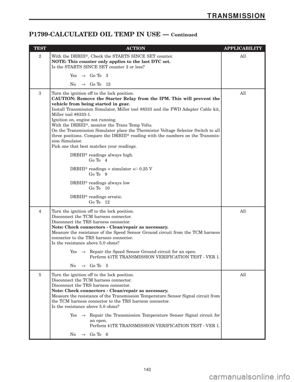
TEST ACTION APPLICABILITY
2 With the DRBIIIt, Check the STARTS SINCE SET counter.
NOTE: This counter only applies to the last DTC set.
Is the STARTS SINCE SET counter 2 or less?All
Ye s®Go To 3
No®Go To 12
3 Turn the ignition off to the lock position.
CAUTION: Remove the Starter Relay from the IPM. This will prevent the
vehicle from being started in gear.
Install Transmission Simulator, Miller tool #8333 and the FWD Adapter Cable kit,
Miller tool #8333-1.
Ignition on, engine not running.
With the DRBIIIt, monitor the Trans Temp Volts.
On the Transmission Simulator place the Thermistor Voltage Selector Switch to all
three positions. Compare the DRBIIItreading with the numbers on the Transmis-
sion Simulator.
Pick one that best matches your readings.All
DRBIIItreadings always high.
Go To 4
DRBIIItreadings = simulator +/- 0.25 V
Go To 9
DRBIIItreadings always low
Go To 10
DRBIIItreadings erratic.
Go To 12
4 Turn the ignition off to the lock position.
Disconnect the TCM harness connector.
Disconnect the TRS harness connector.
Note: Check connectors - Clean/repair as necessary.
Measure the resistance of the Speed Sensor Ground circuit from the TCM harness
connector to the TRS harness connector.
Is the resistance above 5.0 ohms?All
Ye s®Repair the Speed Sensor Ground circuit for an open.
Perform 41TE TRANSMISSION VERIFICATION TEST - VER 1.
No®Go To 5
5 Turn the ignition off to the lock position.
Disconnect the TCM harness connector.
Disconnect the TRS harness connector.
Note: Check connectors - Clean/repair as necessary.
Measure the resistance of the Transmission Temperature Sensor Signal circuit from
the TCM harness connector to the TRS harness connector.
Is the resistance above 5.0 ohms?All
Ye s®Repair the Transmission Temperature Sensor Signal circuit for
an open.
Perform 41TE TRANSMISSION VERIFICATION TEST - VER 1.
No®Go To 6
143
TRANSMISSION
P1799-CALCULATED OIL TEMP IN USE ÐContinued
Page 4248 of 4284
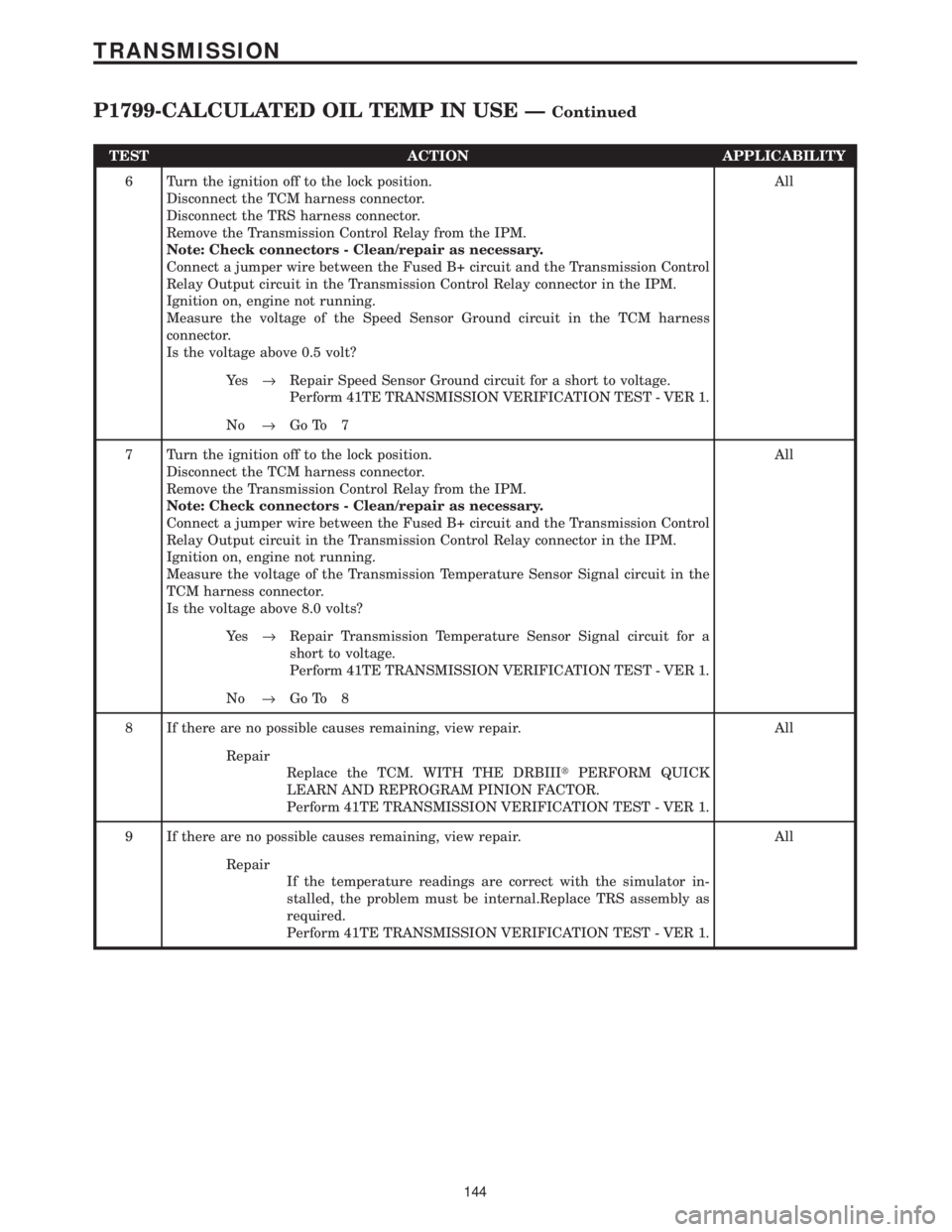
TEST ACTION APPLICABILITY
6 Turn the ignition off to the lock position.
Disconnect the TCM harness connector.
Disconnect the TRS harness connector.
Remove the Transmission Control Relay from the IPM.
Note: Check connectors - Clean/repair as necessary.
Connect a jumper wire between the Fused B+ circuit and the Transmission Control
Relay Output circuit in the Transmission Control Relay connector in the IPM.
Ignition on, engine not running.
Measure the voltage of the Speed Sensor Ground circuit in the TCM harness
connector.
Is the voltage above 0.5 volt?All
Ye s®Repair Speed Sensor Ground circuit for a short to voltage.
Perform 41TE TRANSMISSION VERIFICATION TEST - VER 1.
No®Go To 7
7 Turn the ignition off to the lock position.
Disconnect the TCM harness connector.
Remove the Transmission Control Relay from the IPM.
Note: Check connectors - Clean/repair as necessary.
Connect a jumper wire between the Fused B+ circuit and the Transmission Control
Relay Output circuit in the Transmission Control Relay connector in the IPM.
Ignition on, engine not running.
Measure the voltage of the Transmission Temperature Sensor Signal circuit in the
TCM harness connector.
Is the voltage above 8.0 volts?All
Ye s®Repair Transmission Temperature Sensor Signal circuit for a
short to voltage.
Perform 41TE TRANSMISSION VERIFICATION TEST - VER 1.
No®Go To 8
8 If there are no possible causes remaining, view repair. All
Repair
Replace the TCM. WITH THE DRBIIItPERFORM QUICK
LEARN AND REPROGRAM PINION FACTOR.
Perform 41TE TRANSMISSION VERIFICATION TEST - VER 1.
9 If there are no possible causes remaining, view repair. All
Repair
If the temperature readings are correct with the simulator in-
stalled, the problem must be internal.Replace TRS assembly as
required.
Perform 41TE TRANSMISSION VERIFICATION TEST - VER 1.
144
TRANSMISSION
P1799-CALCULATED OIL TEMP IN USE ÐContinued
Page 4260 of 4284
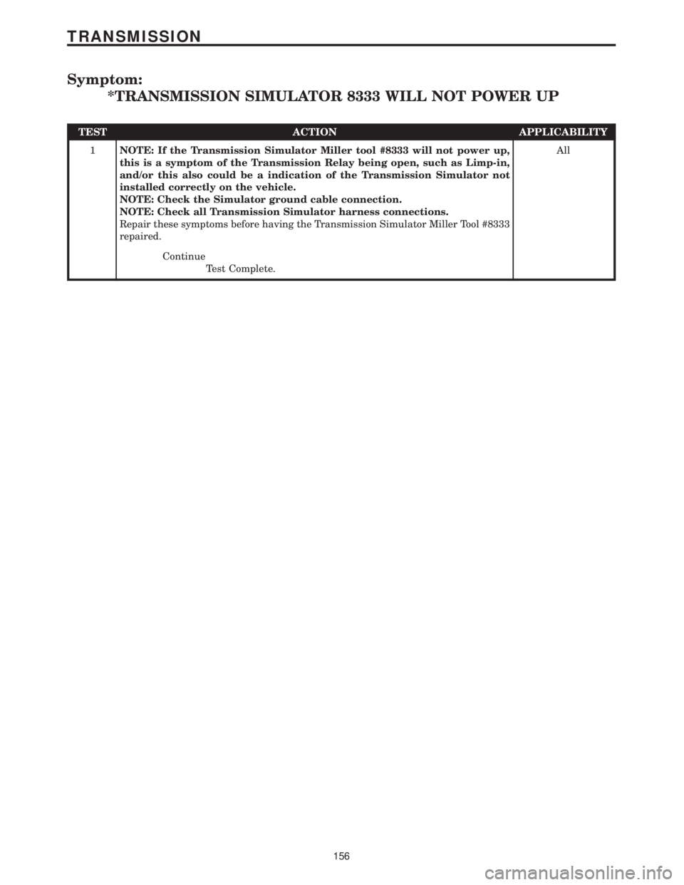
Symptom:
*TRANSMISSION SIMULATOR 8333 WILL NOT POWER UP
TEST ACTION APPLICABILITY
1NOTE: If the Transmission Simulator Miller tool #8333 will not power up,
this is a symptom of the Transmission Relay being open, such as Limp-in,
and/or this also could be a indication of the Transmission Simulator not
installed correctly on the vehicle.
NOTE: Check the Simulator ground cable connection.
NOTE: Check all Transmission Simulator harness connections.
Repair these symptoms before having the Transmission Simulator Miller Tool #8333
repaired.All
Continue
Test Complete.
156
TRANSMISSION
Page 4269 of 4284
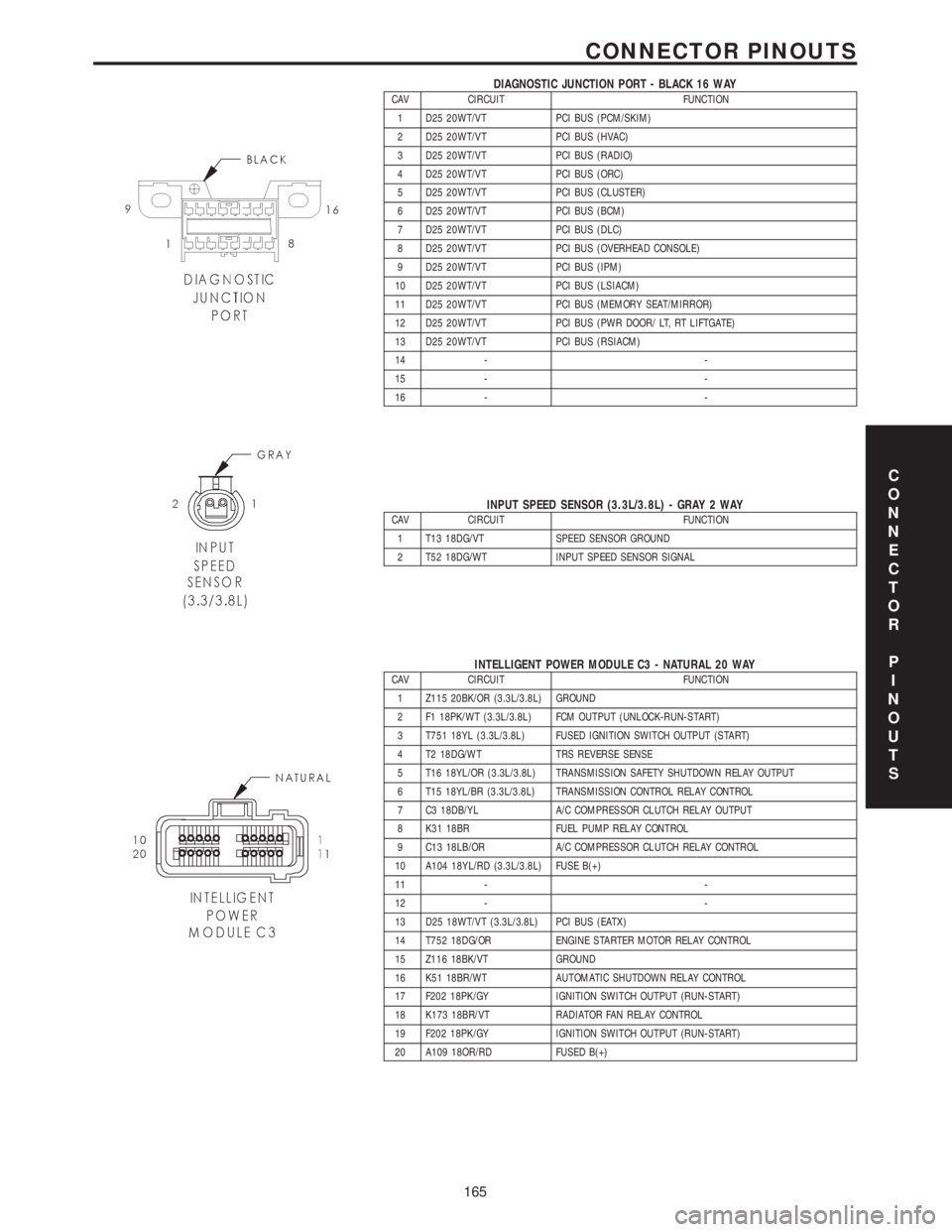
DIAGNOSTIC JUNCTION PORT - BLACK 16 WAYCAV CIRCUIT FUNCTION
1 D25 20WT/VT PCI BUS (PCM/SKIM)
2 D25 20WT/VT PCI BUS (HVAC)
3 D25 20WT/VT PCI BUS (RADIO)
4 D25 20WT/VT PCI BUS (ORC)
5 D25 20WT/VT PCI BUS (CLUSTER)
6 D25 20WT/VT PCI BUS (BCM)
7 D25 20WT/VT PCI BUS (DLC)
8 D25 20WT/VT PCI BUS (OVERHEAD CONSOLE)
9 D25 20WT/VT PCI BUS (IPM)
10 D25 20WT/VT PCI BUS (LSIACM)
11 D25 20WT/VT PCI BUS (MEMORY SEAT/MIRROR)
12 D25 20WT/VT PCI BUS (PWR DOOR/ LT, RT LIFTGATE)
13 D25 20WT/VT PCI BUS (RSIACM)
14 - -
15 - -
16 - -
INPUT SPEED SENSOR (3.3L/3.8L) - GRAY 2 WAYCAV CIRCUIT FUNCTION
1 T13 18DG/VT SPEED SENSOR GROUND
2 T52 18DG/WT INPUT SPEED SENSOR SIGNAL
INTELLIGENT POWER MODULE C3 - NATURAL 20 WAYCAV CIRCUIT FUNCTION
1 Z115 20BK/OR (3.3L/3.8L) GROUND
2 F1 18PK/WT (3.3L/3.8L) FCM OUTPUT (UNLOCK-RUN-START)
3 T751 18YL (3.3L/3.8L) FUSED IGNITION SWITCH OUTPUT (START)
4 T2 18DG/WT TRS REVERSE SENSE
5 T16 18YL/OR (3.3L/3.8L) TRANSMISSION SAFETY SHUTDOWN RELAY OUTPUT
6 T15 18YL/BR (3.3L/3.8L) TRANSMISSION CONTROL RELAY CONTROL
7 C3 18DB/YL A/C COMPRESSOR CLUTCH RELAY OUTPUT
8 K31 18BR FUEL PUMP RELAY CONTROL
9 C13 18LB/OR A/C COMPRESSOR CLUTCH RELAY CONTROL
10 A104 18YL/RD (3.3L/3.8L) FUSE B(+)
11 - -
12 - -
13 D25 18WT/VT (3.3L/3.8L) PCI BUS (EATX)
14 T752 18DG/OR ENGINE STARTER MOTOR RELAY CONTROL
15 Z116 18BK/VT GROUND
16 K51 18BR/WT AUTOMATIC SHUTDOWN RELAY CONTROL
17 F202 18PK/GY IGNITION SWITCH OUTPUT (RUN-START)
18 K173 18BR/VT RADIATOR FAN RELAY CONTROL
19 F202 18PK/GY IGNITION SWITCH OUTPUT (RUN-START)
20 A109 18OR/RD FUSED B(+)
C
O
N
N
E
C
T
O
R
P
I
N
O
U
T
S
165
CONNECTOR PINOUTS
Page 4270 of 4284

INTELLIGENT POWER MODULE C4 - GRAY 10 WAYCAV CIRCUIT FUNCTION
1 Z127 12BK/DG GROUND
2 T750 12YL/GY ENGINE STARTER MOTOR RELAY OUTPUT
3 K342 16BR/WT AUTOMATIC SHUTDOWN RELAY OUTPUT
4 F500 18DG/PK (ANTILOCK
BRAKES)FUSED IGNITION SWITCH RELAY OUTPUT (RUN)
5- -
6 D25 16WT/VT (ANTILOCK
BRAKES)PCI BUS
7 A107 12TN/RD (ANTILOCK
BRAKES)FUSED B(+)
8 A111 12DG/RD (ANTILOCK
BRAKES)FUSED B(+)
9 A701 14BR/RD FUSED B(+)
10 - -
INTELLIGENT POWER MODULE C5 - BLACK 4 WAYCAV CIRCUIT FUNCTION
1 A1 04RD B(+)
2- -
3- -
4- -
INTELLIGENT POWER MODULE C6 - WHITE 10 WAYCAV CIRCUIT FUNCTION
1 A101 12VT/RD FUSED B(+)
2 Z117 16BK/WT GROUND
3 Z118 16BK/YL GROUND
4 A110 12OR/RD (POWER
SEAT)FUSED B(+)
5- -
6- -
7 C7 12DB FUSED FRONT BLOWER MOTOR RELAY OUTPUT
8 F307 16LB/PK (ACCESSO-
RY RELAY POSITION)FUSED ACCESSORY RELAY OUTPUT
8 F307 16LB/PK (BATTERY
POSITION)FUSED B(+)
9 A113 12WT/RD (POWER
SLIDING DOOR)FUSED B(+)
10 - -
C
O
N
N
E
C
T
O
R
P
I
N
O
U
T
S
166
CONNECTOR PINOUTS
Page 4271 of 4284
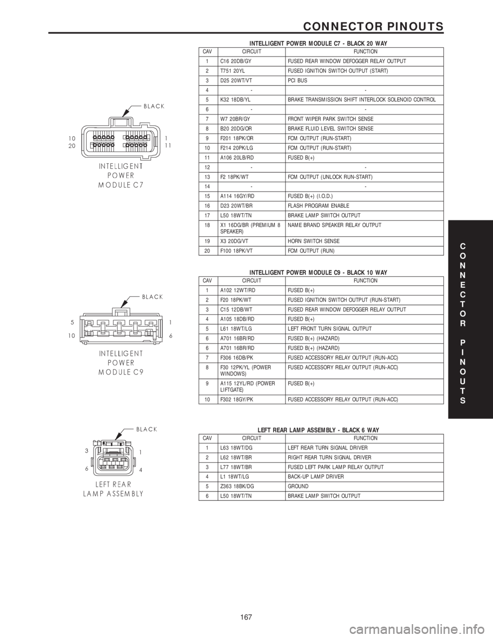
INTELLIGENT POWER MODULE C7 - BLACK 20 WAYCAV CIRCUIT FUNCTION
1 C16 20DB/GY FUSED REAR WINDOW DEFOGGER RELAY OUTPUT
2 T751 20YL FUSED IGNITION SWITCH OUTPUT (START)
3 D25 20WT/VT PCI BUS
4- -
5 K32 18DB/YL BRAKE TRANSMISSION SHIFT INTERLOCK SOLENOID CONTROL
6- -
7 W7 20BR/GY FRONT WIPER PARK SWITCH SENSE
8 B20 20DG/OR BRAKE FLUID LEVEL SWITCH SENSE
9 F201 18PK/OR FCM OUTPUT (RUN-START)
10 F214 20PK/LG FCM OUTPUT (RUN-START)
11 A106 20LB/RD FUSED B(+)
12 - -
13 F2 18PK/WT FCM OUTPUT (UNLOCK RUN-START)
14 - -
15 A114 16GY/RD FUSED B(+) (I.O.D.)
16 D23 20WT/BR FLASH PROGRAM ENABLE
17 L50 18WT/TN BRAKE LAMP SWITCH OUTPUT
18 X1 16DG/BR (PREMIUM 8
SPEAKER)NAME BRAND SPEAKER RELAY OUTPUT
19 X3 20DG/VT HORN SWITCH SENSE
20 F100 18PK/VT FCM OUTPUT (RUN)
INTELLIGENT POWER MODULE C9 - BLACK 10 WAYCAV CIRCUIT FUNCTION
1 A102 12WT/RD FUSED B(+)
2 F20 18PK/WT FUSED IGNITION SWITCH OUTPUT (RUN-START)
3 C15 12DB/WT FUSED REAR WINDOW DEFOGGER RELAY OUTPUT
4 A105 18DB/RD FUSED B(+)
5 L61 18WT/LG LEFT FRONT TURN SIGNAL OUTPUT
6 A701 16BR/RD FUSED B(+) (HAZARD)
6 A701 16BR/RD FUSED B(+) (HAZARD)
7 F306 16DB/PK FUSED ACCESSORY RELAY OUTPUT (RUN-ACC)
8 F30 12PK/YL (POWER
WINDOWS)FUSED ACCESSORY RELAY OUTPUT (RUN-ACC)
9 A115 12YL/RD (POWER
LIFTGATE)FUSED B(+)
10 F302 18GY/PK FUSED ACCESSORY RELAY OUTPUT (RUN-ACC)
LEFT REAR LAMP ASSEMBLY - BLACK 6 WAYCAV CIRCUIT FUNCTION
1 L63 18WT/DG LEFT REAR TURN SIGNAL DRIVER
2 L62 18WT/BR RIGHT REAR TURN SIGNAL DRIVER
3 L77 18WT/BR FUSED LEFT PARK LAMP RELAY OUTPUT
4 L1 18WT/LG BACK-UP LAMP DRIVER
5 Z363 18BK/DG GROUND
6 L50 18WT/TN BRAKE LAMP SWITCH OUTPUT
C
O
N
N
E
C
T
O
R
P
I
N
O
U
T
S
167
CONNECTOR PINOUTS