sensor CHRYSLER VOYAGER 2001 Workshop Manual
[x] Cancel search | Manufacturer: CHRYSLER, Model Year: 2001, Model line: VOYAGER, Model: CHRYSLER VOYAGER 2001Pages: 4284, PDF Size: 83.53 MB
Page 329 of 4284
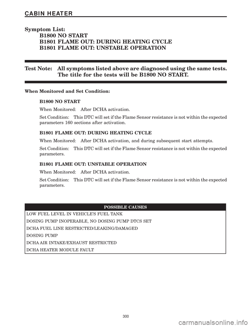
Symptom List:
B1800 NO START
B1801 FLAME OUT: DURING HEATING CYCLE
B1801 FLAME OUT: UNSTABLE OPERATION
Test Note: All symptoms listed above are diagnosed using the same tests.
The title for the tests will be B1800 NO START.
When Monitored and Set Condition:
B1800 NO START
When Monitored: After DCHA activation.
Set Condition: This DTC will set if the Flame Sensor resistance is not within the expected
parameters 160 sections after activation.
B1801 FLAME OUT: DURING HEATING CYCLE
When Monitored: After DCHA activation, and during subsequent start attempts.
Set Condition: This DTC will set if the Flame Sensor resistance is not within the expected
parameters.
B1801 FLAME OUT: UNSTABLE OPERATION
When Monitored: After DCHA activation.
Set Condition: This DTC will set if the Flame Sensor resistance is not within the expected
parameters.
POSSIBLE CAUSES
LOW FUEL LEVEL IN VEHICLE'S FUEL TANK
DOSING PUMP INOPERABLE, NO DOSING PUMP DTCS SET
DCHA FUEL LINE RESTRICTED/LEAKING/DAMAGED
DOSING PUMP
DCHA AIR INTAKE/EXHAUST RESTRICTED
DCHA HEATER MODULE FAULT
300
CABIN HEATER
Page 334 of 4284
TEST ACTION APPLICABILITY
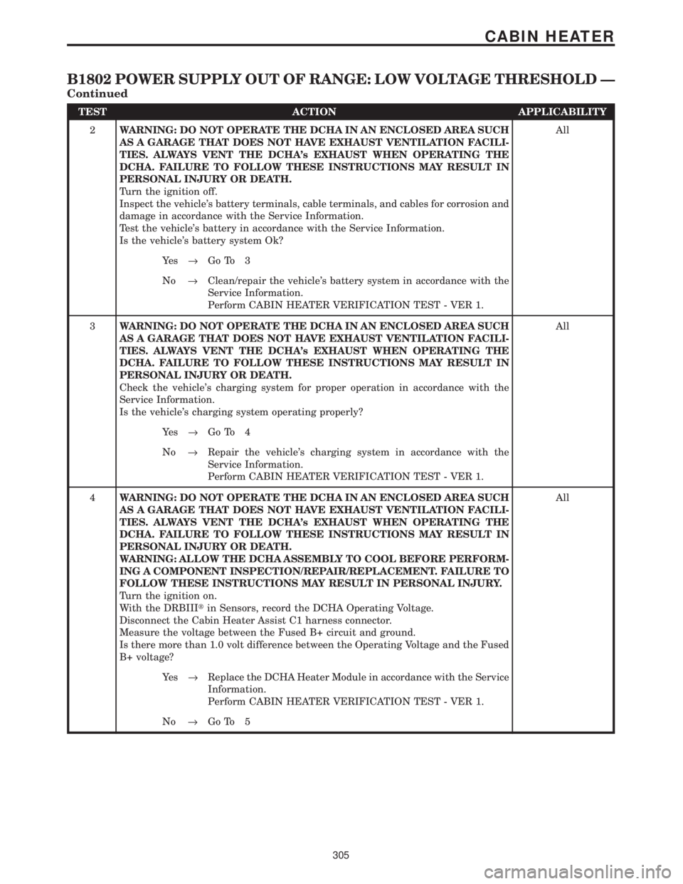
2WARNING: DO NOT OPERATE THE DCHA IN AN ENCLOSED AREA SUCH
AS A GARAGE THAT DOES NOT HAVE EXHAUST VENTILATION FACILI-
TIES. ALWAYS VENT THE DCHA's EXHAUST WHEN OPERATING THE
DCHA. FAILURE TO FOLLOW THESE INSTRUCTIONS MAY RESULT IN
PERSONAL INJURY OR DEATH.
Turn the ignition off.
Inspect the vehicle's battery terminals, cable terminals, and cables for corrosion and
damage in accordance with the Service Information.
Test the vehicle's battery in accordance with the Service Information.
Is the vehicle's battery system Ok?All
Ye s®Go To 3
No®Clean/repair the vehicle's battery system in accordance with the
Service Information.
Perform CABIN HEATER VERIFICATION TEST - VER 1.
3WARNING: DO NOT OPERATE THE DCHA IN AN ENCLOSED AREA SUCH
AS A GARAGE THAT DOES NOT HAVE EXHAUST VENTILATION FACILI-
TIES. ALWAYS VENT THE DCHA's EXHAUST WHEN OPERATING THE
DCHA. FAILURE TO FOLLOW THESE INSTRUCTIONS MAY RESULT IN
PERSONAL INJURY OR DEATH.
Check the vehicle's charging system for proper operation in accordance with the
Service Information.
Is the vehicle's charging system operating properly?All
Ye s®Go To 4
No®Repair the vehicle's charging system in accordance with the
Service Information.
Perform CABIN HEATER VERIFICATION TEST - VER 1.
4WARNING: DO NOT OPERATE THE DCHA IN AN ENCLOSED AREA SUCH
AS A GARAGE THAT DOES NOT HAVE EXHAUST VENTILATION FACILI-
TIES. ALWAYS VENT THE DCHA's EXHAUST WHEN OPERATING THE
DCHA. FAILURE TO FOLLOW THESE INSTRUCTIONS MAY RESULT IN
PERSONAL INJURY OR DEATH.
WARNING: ALLOW THE DCHA ASSEMBLY TO COOL BEFORE PERFORM-
ING A COMPONENT INSPECTION/REPAIR/REPLACEMENT. FAILURE TO
FOLLOW THESE INSTRUCTIONS MAY RESULT IN PERSONAL INJURY.
Turn the ignition on.
With the DRBIIItin Sensors, record the DCHA Operating Voltage.
Disconnect the Cabin Heater Assist C1 harness connector.
Measure the voltage between the Fused B+ circuit and ground.
Is there more than 1.0 volt difference between the Operating Voltage and the Fused
B+ voltage?All
Ye s®Replace the DCHA Heater Module in accordance with the Service
Information.
Perform CABIN HEATER VERIFICATION TEST - VER 1.
No®Go To 5
305
CABIN HEATER
B1802 POWER SUPPLY OUT OF RANGE: LOW VOLTAGE THRESHOLD Ð
Continued
Page 335 of 4284
TEST ACTION APPLICABILITY
5WARNING: DO NOT OPERATE THE DCHA IN AN ENCLOSED AREA SUCH
AS A GARAGE THAT DOES NOT HAVE EXHAUST VENTILATION FACILI-
TIES. ALWAYS VENT THE DCHA's EXHAUST WHEN OPERATING THE
DCHA. FAILURE TO FOLLOW THESE INSTRUCTIONS MAY RESULT IN
PERSONAL INJURY OR DEATH.
WARNING: ALLOW THE DCHA ASSEMBLY TO COOL BEFORE PERFORM-
ING A COMPONENT INSPECTION/REPAIR/REPLACEMENT. FAILURE TO
FOLLOW THESE INSTRUCTIONS MAY RESULT IN PERSONAL INJURY.
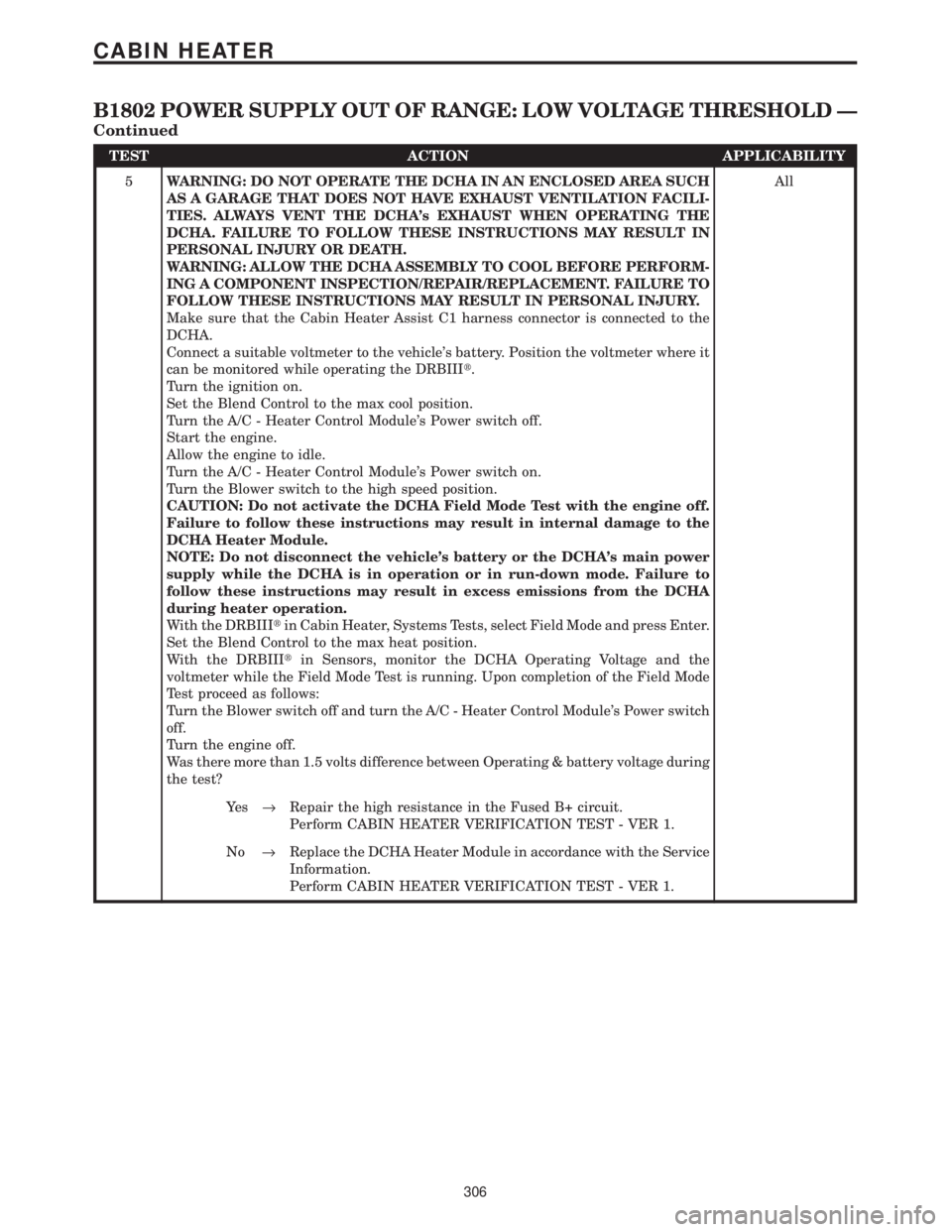
Make sure that the Cabin Heater Assist C1 harness connector is connected to the
DCHA.
Connect a suitable voltmeter to the vehicle's battery. Position the voltmeter where it
can be monitored while operating the DRBIIIt.
Turn the ignition on.
Set the Blend Control to the max cool position.
Turn the A/C - Heater Control Module's Power switch off.
Start the engine.
Allow the engine to idle.
Turn the A/C - Heater Control Module's Power switch on.
Turn the Blower switch to the high speed position.
CAUTION: Do not activate the DCHA Field Mode Test with the engine off.
Failure to follow these instructions may result in internal damage to the
DCHA Heater Module.
NOTE: Do not disconnect the vehicle's battery or the DCHA's main power
supply while the DCHA is in operation or in run-down mode. Failure to
follow these instructions may result in excess emissions from the DCHA
during heater operation.
With the DRBIIItin Cabin Heater, Systems Tests, select Field Mode and press Enter.
Set the Blend Control to the max heat position.
With the DRBIIItin Sensors, monitor the DCHA Operating Voltage and the
voltmeter while the Field Mode Test is running. Upon completion of the Field Mode
Test proceed as follows:
Turn the Blower switch off and turn the A/C - Heater Control Module's Power switch
off.
Turn the engine off.
Was there more than 1.5 volts difference between Operating & battery voltage during
the test?All
Ye s®Repair the high resistance in the Fused B+ circuit.
Perform CABIN HEATER VERIFICATION TEST - VER 1.
No®Replace the DCHA Heater Module in accordance with the Service
Information.
Perform CABIN HEATER VERIFICATION TEST - VER 1.
306
CABIN HEATER
B1802 POWER SUPPLY OUT OF RANGE: LOW VOLTAGE THRESHOLD Ð
Continued
Page 337 of 4284
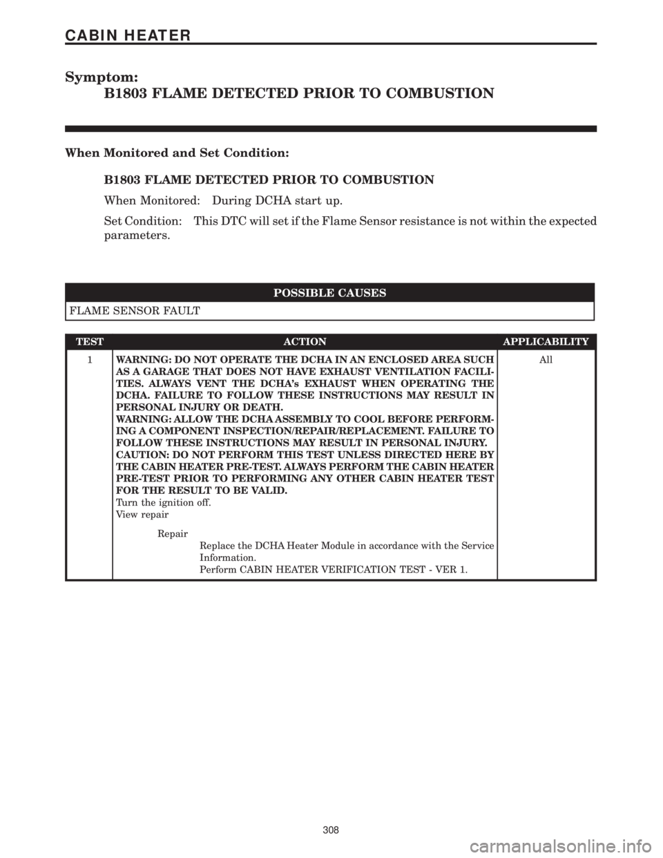
Symptom:
B1803 FLAME DETECTED PRIOR TO COMBUSTION
When Monitored and Set Condition:
B1803 FLAME DETECTED PRIOR TO COMBUSTION
When Monitored: During DCHA start up.
Set Condition: This DTC will set if the Flame Sensor resistance is not within the expected
parameters.
POSSIBLE CAUSES
FLAME SENSOR FAULT
TEST ACTION APPLICABILITY
1WARNING: DO NOT OPERATE THE DCHA IN AN ENCLOSED AREA SUCH
AS A GARAGE THAT DOES NOT HAVE EXHAUST VENTILATION FACILI-
TIES. ALWAYS VENT THE DCHA's EXHAUST WHEN OPERATING THE
DCHA. FAILURE TO FOLLOW THESE INSTRUCTIONS MAY RESULT IN
PERSONAL INJURY OR DEATH.
WARNING: ALLOW THE DCHA ASSEMBLY TO COOL BEFORE PERFORM-
ING A COMPONENT INSPECTION/REPAIR/REPLACEMENT. FAILURE TO
FOLLOW THESE INSTRUCTIONS MAY RESULT IN PERSONAL INJURY.
CAUTION: DO NOT PERFORM THIS TEST UNLESS DIRECTED HERE BY
THE CABIN HEATER PRE-TEST. ALWAYS PERFORM THE CABIN HEATER
PRE-TEST PRIOR TO PERFORMING ANY OTHER CABIN HEATER TEST
FOR THE RESULT TO BE VALID.
Turn the ignition off.
View repairAll
Repair
Replace the DCHA Heater Module in accordance with the Service
Information.
Perform CABIN HEATER VERIFICATION TEST - VER 1.
308
CABIN HEATER
Page 338 of 4284
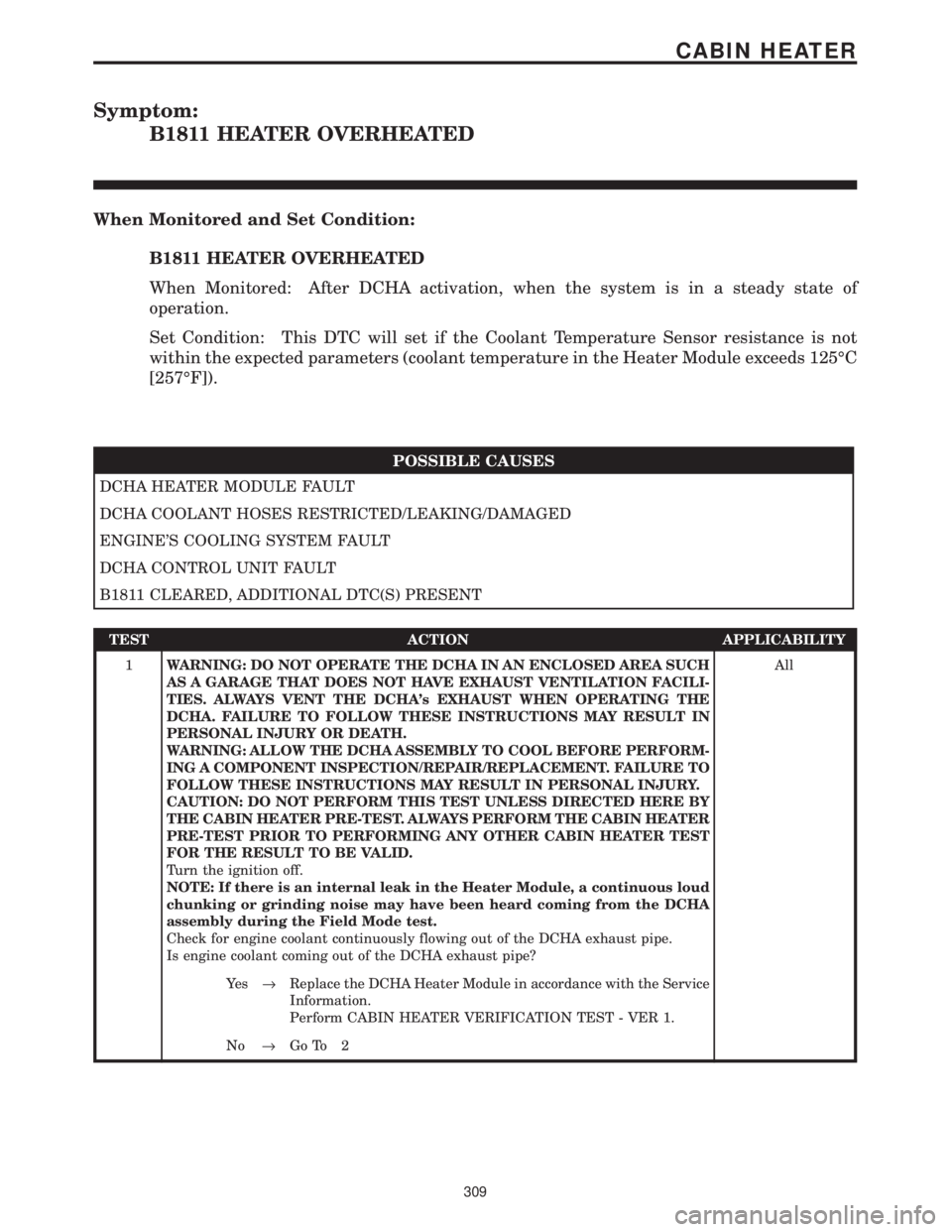
Symptom:
B1811 HEATER OVERHEATED
When Monitored and Set Condition:
B1811 HEATER OVERHEATED
When Monitored: After DCHA activation, when the system is in a steady state of
operation.
Set Condition: This DTC will set if the Coolant Temperature Sensor resistance is not
within the expected parameters (coolant temperature in the Heater Module exceeds 125ÉC
[257ÉF]).
POSSIBLE CAUSES
DCHA HEATER MODULE FAULT
DCHA COOLANT HOSES RESTRICTED/LEAKING/DAMAGED
ENGINE'S COOLING SYSTEM FAULT
DCHA CONTROL UNIT FAULT
B1811 CLEARED, ADDITIONAL DTC(S) PRESENT
TEST ACTION APPLICABILITY
1WARNING: DO NOT OPERATE THE DCHA IN AN ENCLOSED AREA SUCH
AS A GARAGE THAT DOES NOT HAVE EXHAUST VENTILATION FACILI-
TIES. ALWAYS VENT THE DCHA's EXHAUST WHEN OPERATING THE
DCHA. FAILURE TO FOLLOW THESE INSTRUCTIONS MAY RESULT IN
PERSONAL INJURY OR DEATH.
WARNING: ALLOW THE DCHA ASSEMBLY TO COOL BEFORE PERFORM-
ING A COMPONENT INSPECTION/REPAIR/REPLACEMENT. FAILURE TO
FOLLOW THESE INSTRUCTIONS MAY RESULT IN PERSONAL INJURY.
CAUTION: DO NOT PERFORM THIS TEST UNLESS DIRECTED HERE BY
THE CABIN HEATER PRE-TEST. ALWAYS PERFORM THE CABIN HEATER
PRE-TEST PRIOR TO PERFORMING ANY OTHER CABIN HEATER TEST
FOR THE RESULT TO BE VALID.
Turn the ignition off.
NOTE: If there is an internal leak in the Heater Module, a continuous loud
chunking or grinding noise may have been heard coming from the DCHA
assembly during the Field Mode test.
Check for engine coolant continuously flowing out of the DCHA exhaust pipe.
Is engine coolant coming out of the DCHA exhaust pipe?All
Ye s®Replace the DCHA Heater Module in accordance with the Service
Information.
Perform CABIN HEATER VERIFICATION TEST - VER 1.
No®Go To 2
309
CABIN HEATER
Page 351 of 4284
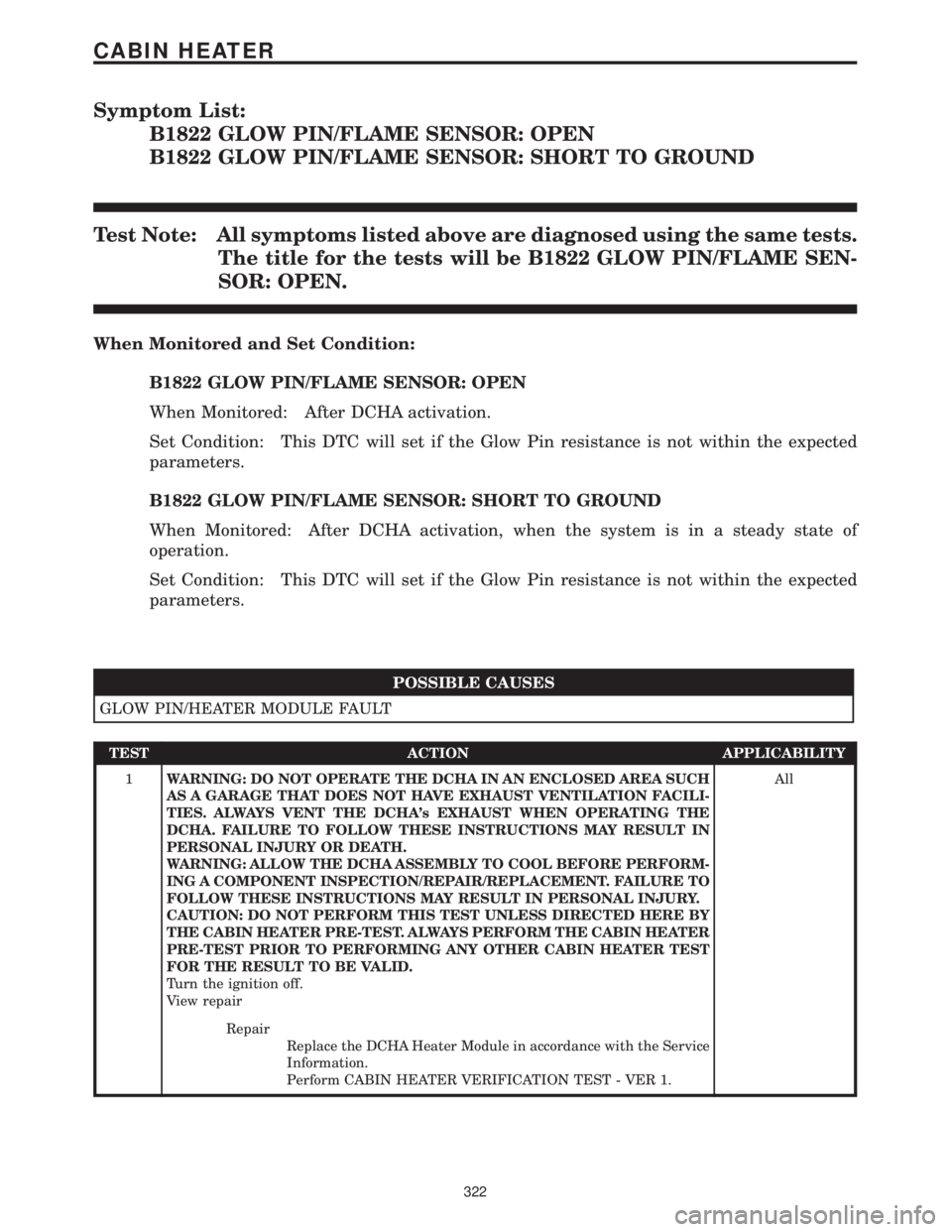
Symptom List:
B1822 GLOW PIN/FLAME SENSOR: OPEN
B1822 GLOW PIN/FLAME SENSOR: SHORT TO GROUND
Test Note: All symptoms listed above are diagnosed using the same tests.
The title for the tests will be B1822 GLOW PIN/FLAME SEN-
SOR: OPEN.
When Monitored and Set Condition:
B1822 GLOW PIN/FLAME SENSOR: OPEN
When Monitored: After DCHA activation.
Set Condition: This DTC will set if the Glow Pin resistance is not within the expected
parameters.
B1822 GLOW PIN/FLAME SENSOR: SHORT TO GROUND
When Monitored: After DCHA activation, when the system is in a steady state of
operation.
Set Condition: This DTC will set if the Glow Pin resistance is not within the expected
parameters.
POSSIBLE CAUSES
GLOW PIN/HEATER MODULE FAULT
TEST ACTION APPLICABILITY
1WARNING: DO NOT OPERATE THE DCHA IN AN ENCLOSED AREA SUCH
AS A GARAGE THAT DOES NOT HAVE EXHAUST VENTILATION FACILI-
TIES. ALWAYS VENT THE DCHA's EXHAUST WHEN OPERATING THE
DCHA. FAILURE TO FOLLOW THESE INSTRUCTIONS MAY RESULT IN
PERSONAL INJURY OR DEATH.
WARNING: ALLOW THE DCHA ASSEMBLY TO COOL BEFORE PERFORM-
ING A COMPONENT INSPECTION/REPAIR/REPLACEMENT. FAILURE TO
FOLLOW THESE INSTRUCTIONS MAY RESULT IN PERSONAL INJURY.
CAUTION: DO NOT PERFORM THIS TEST UNLESS DIRECTED HERE BY
THE CABIN HEATER PRE-TEST. ALWAYS PERFORM THE CABIN HEATER
PRE-TEST PRIOR TO PERFORMING ANY OTHER CABIN HEATER TEST
FOR THE RESULT TO BE VALID.
Turn the ignition off.
View repairAll
Repair
Replace the DCHA Heater Module in accordance with the Service
Information.
Perform CABIN HEATER VERIFICATION TEST - VER 1.
322
CABIN HEATER
Page 379 of 4284
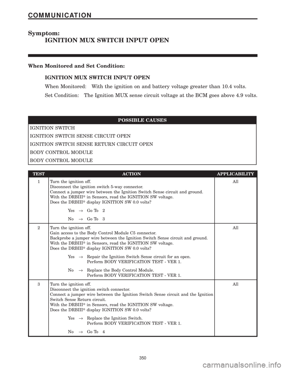
Symptom:
IGNITION MUX SWITCH INPUT OPEN
When Monitored and Set Condition:
IGNITION MUX SWITCH INPUT OPEN
When Monitored: With the ignition on and battery voltage greater than 10.4 volts.
Set Condition: The Ignition MUX sense circuit voltage at the BCM goes above 4.9 volts.
POSSIBLE CAUSES
IGNITION SWITCH
IGNITION SWITCH SENSE CIRCUIT OPEN
IGNITION SWITCH SENSE RETURN CIRCUIT OPEN
BODY CONTROL MODULE
BODY CONTROL MODULE
TEST ACTION APPLICABILITY
1 Turn the ignition off.
Disconnect the ignition switch 5-way connector.
Connect a jumper wire between the Ignition Switch Sense circuit and ground.
With the DRBIIItin Sensors, read the IGNITION SW voltage.
Does the DRBIIItdisplay IGNITION SW 0.0 volts?All
Ye s®Go To 2
No®Go To 3
2 Turn the ignition off.
Gain access to the Body Control Module C5 connector.
Backprobe a jumper wire between the Ignition Switch Sense circuit and ground.
With the DRBIIItin Sensors, read the IGNITION SW voltage.
Does the DRBIIItdisplay IGNITION SW 0.0 volts?All
Ye s®Repair the Ignition Switch Sense circuit for an open.
Perform BODY VERIFICATION TEST - VER 1.
No®Replace the Body Control Module.
Perform BODY VERIFICATION TEST - VER 1.
3 Turn the ignition off.
Disconnect the ignition switch connector.
Connect a jumper wire between the Ignition Switch Sense circuit and the Ignition
Switch Sense Return circuit.
With the DRBIIItin Sensors, read the IGNITION SW voltage.
Does the DRBIIItdisplay IGNITION SW 0.0 volts?All
Ye s®Replace the Ignition Switch.
Perform BODY VERIFICATION TEST - VER 1.
No®Go To 4
350
COMMUNICATION
Page 380 of 4284
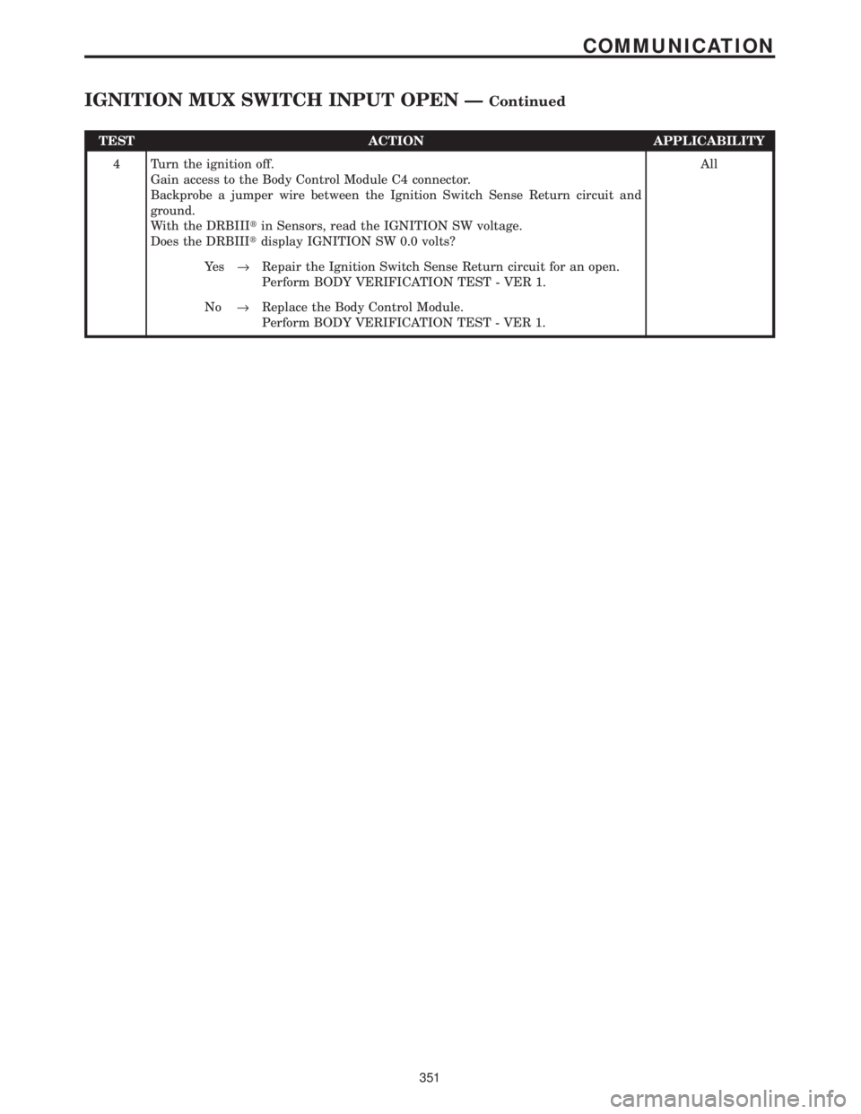
TEST ACTION APPLICABILITY
4 Turn the ignition off.
Gain access to the Body Control Module C4 connector.
Backprobe a jumper wire between the Ignition Switch Sense Return circuit and
ground.
With the DRBIIItin Sensors, read the IGNITION SW voltage.
Does the DRBIIItdisplay IGNITION SW 0.0 volts?All
Ye s®Repair the Ignition Switch Sense Return circuit for an open.
Perform BODY VERIFICATION TEST - VER 1.
No®Replace the Body Control Module.
Perform BODY VERIFICATION TEST - VER 1.
351
COMMUNICATION
IGNITION MUX SWITCH INPUT OPEN ÐContinued
Page 381 of 4284
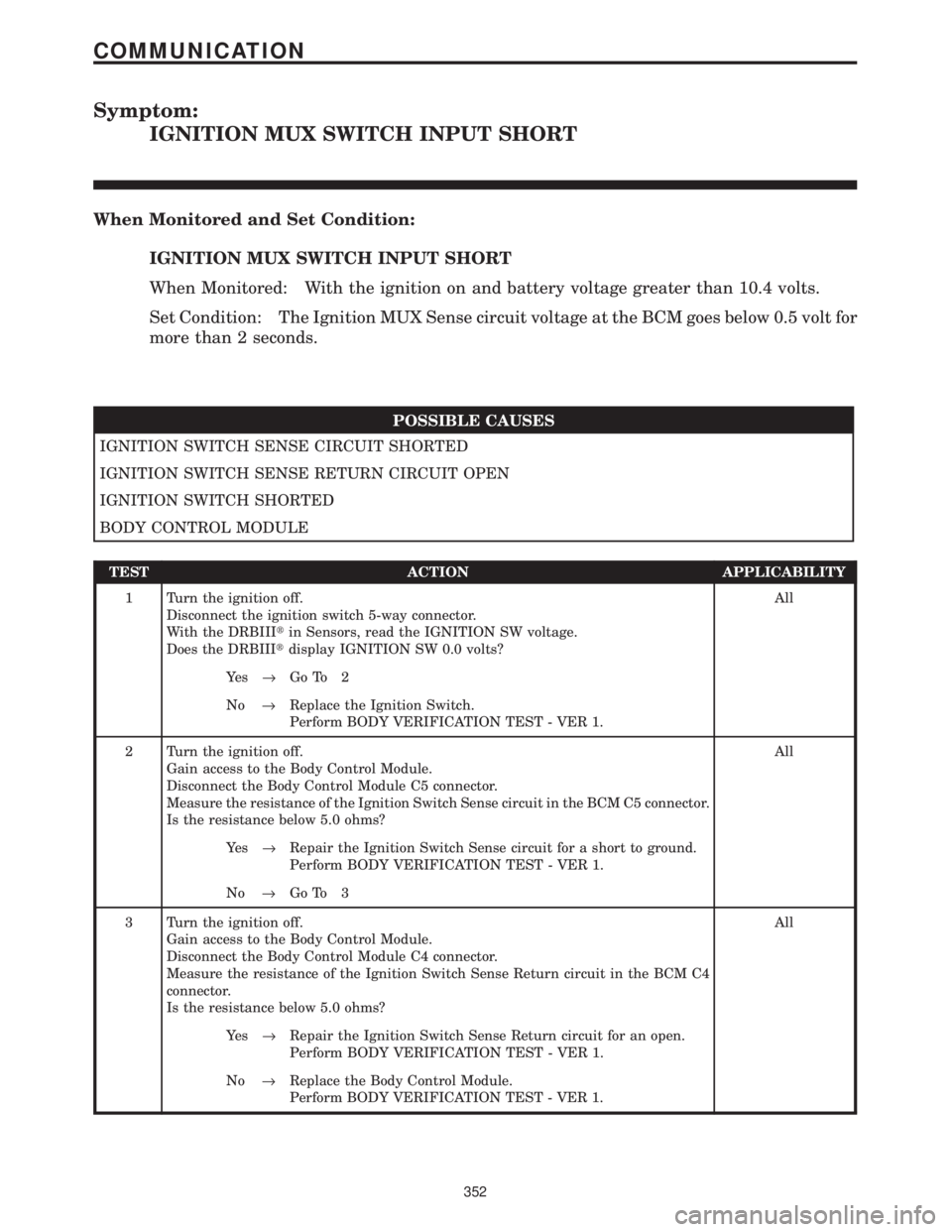
Symptom:
IGNITION MUX SWITCH INPUT SHORT
When Monitored and Set Condition:
IGNITION MUX SWITCH INPUT SHORT
When Monitored: With the ignition on and battery voltage greater than 10.4 volts.
Set Condition: The Ignition MUX Sense circuit voltage at the BCM goes below 0.5 volt for
more than 2 seconds.
POSSIBLE CAUSES
IGNITION SWITCH SENSE CIRCUIT SHORTED
IGNITION SWITCH SENSE RETURN CIRCUIT OPEN
IGNITION SWITCH SHORTED
BODY CONTROL MODULE
TEST ACTION APPLICABILITY
1 Turn the ignition off.
Disconnect the ignition switch 5-way connector.
With the DRBIIItin Sensors, read the IGNITION SW voltage.
Does the DRBIIItdisplay IGNITION SW 0.0 volts?All
Ye s®Go To 2
No®Replace the Ignition Switch.
Perform BODY VERIFICATION TEST - VER 1.
2 Turn the ignition off.
Gain access to the Body Control Module.
Disconnect the Body Control Module C5 connector.
Measure the resistance of the Ignition Switch Sense circuit in the BCM C5 connector.
Is the resistance below 5.0 ohms?All
Ye s®Repair the Ignition Switch Sense circuit for a short to ground.
Perform BODY VERIFICATION TEST - VER 1.
No®Go To 3
3 Turn the ignition off.
Gain access to the Body Control Module.
Disconnect the Body Control Module C4 connector.
Measure the resistance of the Ignition Switch Sense Return circuit in the BCM C4
connector.
Is the resistance below 5.0 ohms?All
Ye s®Repair the Ignition Switch Sense Return circuit for an open.
Perform BODY VERIFICATION TEST - VER 1.
No®Replace the Body Control Module.
Perform BODY VERIFICATION TEST - VER 1.
352
COMMUNICATION
Page 472 of 4284
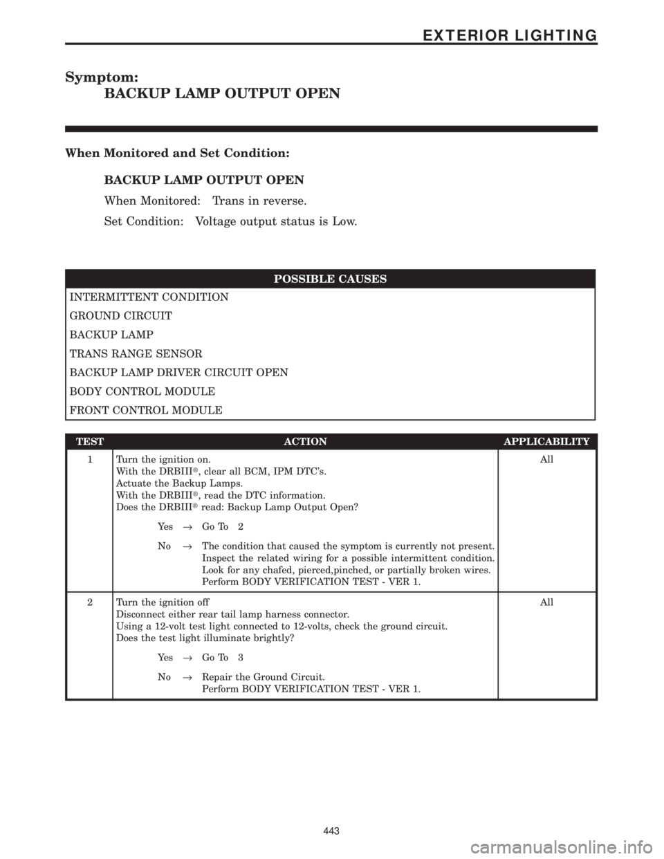
Symptom:
BACKUP LAMP OUTPUT OPEN
When Monitored and Set Condition:
BACKUP LAMP OUTPUT OPEN
When Monitored: Trans in reverse.
Set Condition: Voltage output status is Low.
POSSIBLE CAUSES
INTERMITTENT CONDITION
GROUND CIRCUIT
BACKUP LAMP
TRANS RANGE SENSOR
BACKUP LAMP DRIVER CIRCUIT OPEN
BODY CONTROL MODULE
FRONT CONTROL MODULE
TEST ACTION APPLICABILITY
1 Turn the ignition on.
With the DRBIIIt, clear all BCM, IPM DTC's.
Actuate the Backup Lamps.
With the DRBIIIt, read the DTC information.
Does the DRBIIItread: Backup Lamp Output Open?All
Ye s®Go To 2
No®The condition that caused the symptom is currently not present.
Inspect the related wiring for a possible intermittent condition.
Look for any chafed, pierced,pinched, or partially broken wires.
Perform BODY VERIFICATION TEST - VER 1.
2 Turn the ignition off
Disconnect either rear tail lamp harness connector.
Using a 12-volt test light connected to 12-volts, check the ground circuit.
Does the test light illuminate brightly?All
Ye s®Go To 3
No®Repair the Ground Circuit.
Perform BODY VERIFICATION TEST - VER 1.
443
EXTERIOR LIGHTING