sensor CHRYSLER VOYAGER 2001 Service Manual
[x] Cancel search | Manufacturer: CHRYSLER, Model Year: 2001, Model line: VOYAGER, Model: CHRYSLER VOYAGER 2001Pages: 4284, PDF Size: 83.53 MB
Page 2923 of 4284
OPERATION
The ECM uses the mass air flow (MAF) sensor to
measure air density. The MAF sensor contains a
ceramic element. A signal voltage is provided to the
element. As engine speed increases, airflow across
the ceramic element increases. Changes in air flow
and air density cause the temperature of the ceramic
element to fluxuate. The ceramic element changes
resistance respectively to changes in temperature.
The change in resistance varies the signal voltage
output to the ECM. The diesel power relay supplies
battery power the to MAF sensor. Ground is provided
by the ECM. The MAF sensor signal is provided by
the ECM.
REMOVAL
(1) Disconnect negative battery cable.
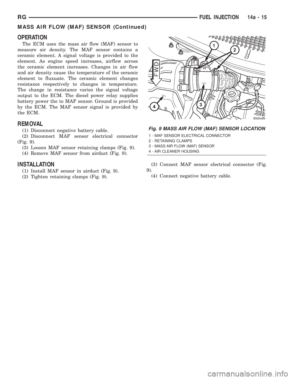
(2) Disconnect MAF sensor electrical connector
(Fig. 9).
(3) Loosen MAF sensor retaining clamps (Fig. 9).
(4) Remove MAF sensor from airduct (Fig. 9).
INSTALLATION
(1) Install MAF sensor in airduct (Fig. 9).
(2) Tighten retaining clamps (Fig. 9).(3) Connect MAF sensor electrical connector (Fig.
9).
(4) Connect negative battery cable.
Fig. 9 MASS AIR FLOW (MAF) SENSOR LOCATION
1 - MAF SENSOR ELECTRICAL CONNECTOR
2 - RETAINING CLAMPS
3 - MASS AIR FLOW (MAF) SENSOR
4 - AIR CLEANER HOUSING
RGFUEL INJECTION14a-15
MASS AIR FLOW (MAF) SENSOR (Continued)
Page 2949 of 4284
SERVICE WARNINGS AND CAUTIONS
WARNING: POWER STEERING FLUID, ENGINE
PARTS AND EXHAUST SYSTEM MAY BE
EXTREMELY HOT IF ENGINE HAS BEEN RUNNING.
DO NOT START ENGINE WITH ANY LOOSE OR DIS-
CONNECTED HOSES. DO NOT ALLOW HOSES TO
TOUCH HOT EXHAUST MANIFOLD OR CATALYST.
WARNING: FLUID LEVEL SHOULD BE CHECKED
WITH THE ENGINE OFF TO PREVENT PERSONAL
INJURY FROM MOVING PARTS.
CAUTION: When the system is open, cap all open
ends of the hoses, power steering pump fittings or
power steering gear ports to prevent entry of for-
eign material into the components.
STANDARD PROCEDURE - POWER STEERING
PUMP INITIAL OPERATION
CAUTION: The fluid level should be checked with
engine off to prevent injury from moving compo-
nents. Use only MoparTPower Steering Fluid (MS-
5931) or approved equivalent. Do not overfill.
Read the fluid level through the side of the power
steering fluid reservoir. The fluid level should indi-
cateªFILL RANGEºwhen the fluid is at a temper-
ature of approximately 21ÉC to 27ÉC (70ÉF to 80ÉF).
(1) Wipe the filler cap and area clean, then remove
the cap.
(2) Fill the fluid reservoir to the proper level and
let the fluid settle for at least two (2) minutes.
(3) Start the engine and let run for a few seconds,
then turn the engine off.
(4) Add fluid if necessary. Repeat the above steps
until the fluid level remains constant after running
the engine.
(5) Raise the front wheels off the ground.
(6) Start the engine.
(7) Slowly turn the steering wheel right and left,
lightly contacting the wheel stops.
(8) Add fluid if necessary.
(9) Lower the vehicle, then turn the steering wheel
slowly from lock-to-lock.
(10) Stop the engine. Check the fluid level and
refill as required.
(11) If the fluid is extremely foamy, allow the vehi-
cle to stabilize a few minutes, then repeat the above
procedure.
REMOVAL - PUMP (2.4L ENGINE)
(1) Remove the (-) negative battery cable from the
battery and isolate cable.
(2) Remove the cap from the power steering fluid
reservoir.
(3) Using a siphon pump, remove as much power
steering fluid as possible from the power steering
fluid reservoir.
(4) Raise the vehicle on jack stands or centered on
a frame contact type hoist. See Hoisting in Lubrica-
tion and Maintenance.
(5) Disconnect the oxygen sensor wiring harness
from the vehicle wiring harness at the rear engine
mount bracket.
NOTE: The exhaust system needs to be removed
from the engine to allow for an area to remove the
power steering pump from the vehicle.
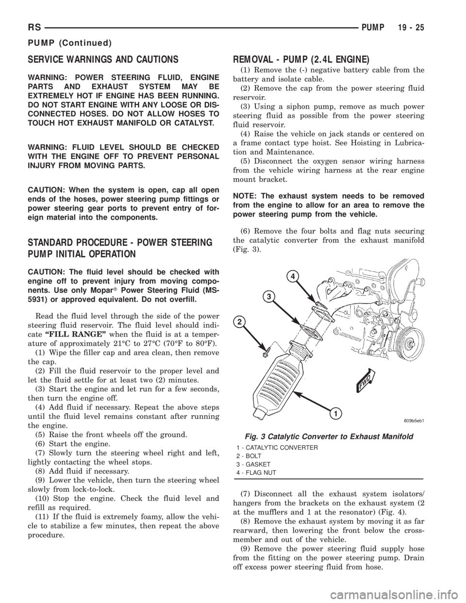
(6) Remove the four bolts and flag nuts securing
the catalytic converter from the exhaust manifold
(Fig. 3).
(7) Disconnect all the exhaust system isolators/
hangers from the brackets on the exhaust system (2
at the mufflers and 1 at the resonator) (Fig. 4).
(8) Remove the exhaust system by moving it as far
rearward, then lowering the front below the cross-
member and out of the vehicle.
(9) Remove the power steering fluid supply hose
from the fitting on the power steering pump. Drain
off excess power steering fluid from hose.
Fig. 3 Catalytic Converter to Exhaust Manifold
1 - CATALYTIC CONVERTER
2 - BOLT
3 - GASKET
4 - FLAG NUT
RSPUMP19-25
PUMP (Continued)
Page 2953 of 4284
INSTALLATION - PUMP (2.4L ENGINE)
(1) Install power steering pump back in vehicle
using the reverse order of its removal through the
exhaust tunnel are of the vehicle.
(2) Install the power steering pump on its cast
mounting bracket (Fig. 7), then install the nut and
bolt attaching the front bracket to the cast bracket
(Fig. 8).Do not fully tighten at this time..
(3) Install the rear nut (Fig. 7).
(4) Install the power steering pump drive belt on
pulley and adjust (Refer to 7 - COOLING/ACCES-
SORY DRIVE/DRIVE BELTS - INSTALLATION).(5) Tighten the two adjustment slot bolts and the
one pivot bolt to 54 N´m (40 ft.lbs.) torque.
(6) Install the accessory drive splash shield.
NOTE: Before installing power steering fluid pres-
sure hose on power steering pump, inspect the
O-ring on the pressure hose for damage and
replace if necessary.
(7) Install the power steering fluid pressure line
onto the output fitting of the power steering pump
(Fig. 6). Tighten the pressure line to pump fitting
tube nut to a torque of 31 N´m (275 in. lbs.).
(8) Install the power steering fluid low pressure
return hose on the power steering pump low pressure
fitting (Fig. 6).Be sure hose clamps are properly
reinstalled.
(9) Install the power steering fluid supply hose on
the power steering pump fluid fitting.Be sure hose
is clear of accessory drive belts all hose clamps
are properly reinstalled.
(10) When used, properly position the protective
heat sleeve on the power steering return hose. Tie
strap the heat sleeve to the power steering hose to
keep in it's proper position.
(11) Install the exhaust system (Fig. 4). Install all
exhaust system isolators/hangers on the exhaust sys-
tem brackets, then the four bolts and flag nuts (Fig.
3).
(12) Connect the oxygen sensor wiring harness to
the vehicle wiring harness.
(13) Lower vehicle.
(14) Connect the negative battery cable on the
negative battery post.
(15) Perform the POWER STEERING PUMP INI-
TIAL OPERATION procedure to properly fill and
bleed the power steering system. (Refer to 19 -
STEERING/PUMP - STANDARD PROCEDURE)
(16) Inspect for leaks.
INSTALLATION - PUMP (3.3L/3.8L ENGINE)
(1) Install power steering pump back in vehicle
using the reverse order of its removal through the
engine compartment of the vehicle.
(2) Install the power steering pump on its mount-
ing bracket.
(3) Install the 3 front and 1 rear power steering
pump mounting bolts (Fig. 9). Remember to place
spacer between pump and rear mounting bracket
when installing rear mounting bolt. Tighten the
power steering pump mounting bolts to a torque of
54 N´m (40 ft. lbs.).
NOTE: Before installing power steering pressure
hose on power steering pump, inspect the O-ring
on the power steering pressure hose for damage
and replace if required.
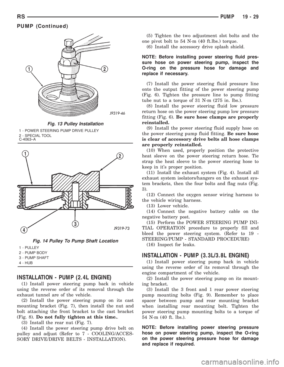
Fig. 13 Pulley Installation
1 - POWER STEERING PUMP DRIVE PULLEY
2 - SPECIAL TOOL
C-4063±A
Fig. 14 Pulley To Pump Shaft Location
1 - PULLEY
2 - PUMP BODY
3 - PUMP SHAFT
4 - HUB
RSPUMP19-29
PUMP (Continued)
Page 2986 of 4284
REMOVAL.............................118
INSTALLATION..........................118
THROTTLE VALVE CABLE
REMOVAL.............................118
INSTALLATION..........................118
ADJUSTMENTS.........................120
TORQUE CONVERTER
DESCRIPTION..........................120
OPERATION............................123
REMOVAL.............................125
INSTALLATION..........................125
TRANSFER SYSTEM - OUTPUT SHAFT/GEAR/
BEARING
REMOVAL.............................126
INSTALLATION..........................129
ADJUSTMENTS.........................132TRANSFER SYSTEM - TRANSFER SHAFT/
GEAR/BEARING
REMOVAL.............................134
INSTALLATION..........................137
ADJUSTMENTS.........................142
VALVE BODY
REMOVAL.............................142
DISASSEMBLY..........................145
CLEANING.............................151
INSPECTION...........................152
ASSEMBLY............................152
INSTALLATION..........................155
ADJUSTMENTS.........................157
VEHICLE SPEED SENSOR/PINION GEAR
REMOVAL.............................157
INSTALLATION..........................157
AUTOMATIC - 31TH
DESCRIPTION
This transaxle combines torque converter, three
speed transmission, final drive gearing, and differen-
tial into a front wheel drive system.
Within this transaxle, there are three primary
areas:
(1) Main center line plus valve body.
(2) Transfer shaft center line (includes governor
and parking sprag).
(3) Differential center line.
Center distances between the main rotating parts
in these three areas are held precise to maintain a
low noise level.
The torque converter, transaxle area, and differen-
tial are housed in an integral aluminum die casting.
The differential oil sump is common with the
transaxle sump. Separate filling of the differen-
tial is NOT necessary.
The torque converter is attached to the crankshaft
through a flexible driving plate. Cooling of the con-
verter is accomplished by circulating the transaxle
fluid through a remote cooler. There are two types of
coolers used. An oil-to-water type cooler located in
the radiator side tank and/or an oil-to-air heat
exchanger. The torque converter assembly is a sealed
unit that cannot be disassembled.
The transaxle fluid is filtered by an internal filter
attached to the lower side of the valve body assembly.Engine torque is transmitted to the torque con-
verter and then through the input shaft to multiple-
disc clutches in the transaxle. The power flow
depends on the application of the clutches and bands.
Refer to Elements in Use Chart in Diagnosis and
Tests section.
The transaxle consists of:
²Two multiple-disc clutches
²An overrunning clutch
²Two servos
²A hydraulic accumulator
²Two bands
²Two planetary gear sets
This provides three forward ratios and a reverse
ratio. The common sun gear of the planetary gear
sets is connected to the front clutch by a driving
shell. The driving shell is splined to the sun gear and
front clutch retainer. The hydraulic system consists
of an oil pump and a single valve body which con-
tains all of the valves except the governor valves.
The transaxle sump and differential sump are both
vented through the dipstick. Output torque from the
main center line is delivered through helical gears to
the transfer shaft. This gear set is a factor in the
transaxle final drive (axle) ratio. The shaft also car-
ries the governor and parking sprag. An integral heli-
cal gear on the transfer shaft drives the differential
ring gear.
21 - 22 AUTOMATIC - 31THRS
Page 3002 of 4284
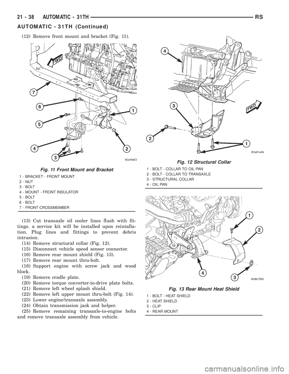
(12) Remove front mount and bracket (Fig. 11).
(13) Cut transaxle oil cooler lines flush with fit-
tings. a service kit will be installed upon reintalla-
tion. Plug lines and fittings to prevent debris
intrusion.
(14) Remove structural collar (Fig. 12).
(15) Disconnect vehicle speed sensor connector.
(16) Remove rear mount shield (Fig. 13).
(17) Remove rear mount thru-bolt.
(18) Support engine with screw jack and wood
block.
(19) Remove cradle plate.
(20) Remove torque converter-to-drive plate bolts.
(21) Remove left wheel splash shield.
(22) Remove left upper mount thru-bolt (Fig. 14).
(23) Lower engine/transaxle assembly.
(24) Obtain transmission jack and helper.
(25) Remove remaining transaxle-to-engine bolts
and remove transaxle assembly from vehicle.
Fig. 11 Front Mount and Bracket
1 - BRACKET - FRONT MOUNT
2 - NUT
3 - BOLT
4 - MOUNT - FRONT INSULATOR
5 - BOLT
6 - BOLT
7 - FRONT CROSSMEMBER
Fig. 12 Structural Collar
1 - BOLT - COLLAR TO OIL PAN
2 - BOLT - COLLAR TO TRANSAXLE
3 - STRUCTURAL COLLAR
4 - OIL PAN
Fig. 13 Rear Mount Heat Shield
1 - BOLT - HEAT SHIELD
2 - HEAT SHIELD
3 - CLIP
4 - REAR MOUNT
21 - 38 AUTOMATIC - 31THRS
AUTOMATIC - 31TH (Continued)
Page 3024 of 4284
(4) Install left wheel splash shield.
(5) Install torque converter-to-drive plate bolts and
torque to 88 N´m (65 ft. lbs.).
(6) Install cradle plate.
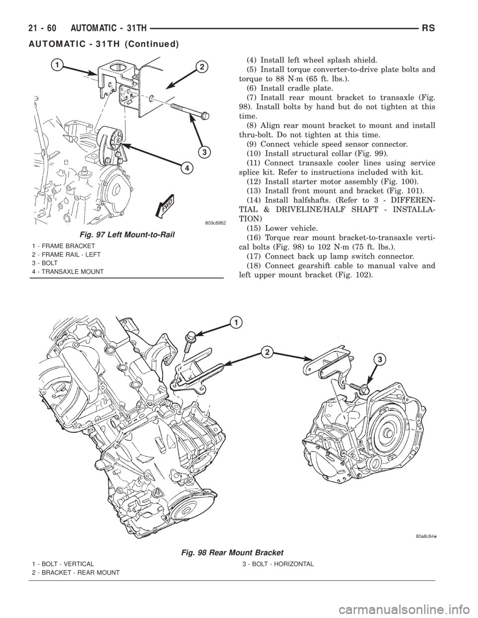
(7) Install rear mount bracket to transaxle (Fig.
98). Install bolts by hand but do not tighten at this
time.
(8) Align rear mount bracket to mount and install
thru-bolt. Do not tighten at this time.
(9) Connect vehicle speed sensor connector.
(10) Install structural collar (Fig. 99).
(11) Connect transaxle cooler lines using service
splice kit. Refer to instructions included with kit.
(12) Install starter motor assembly (Fig. 100).
(13) Install front mount and bracket (Fig. 101).
(14)
Install halfshafts. (Refer to 3 - DIFFEREN-
TIAL & DRIVELINE/HALF SHAFT - INSTALLA-
TION)
(15) Lower vehicle.
(16) Torque rear mount bracket-to-transaxle verti-
cal bolts (Fig. 98) to 102 N´m (75 ft. lbs.).
(17) Connect back up lamp switch connector.
(18) Connect gearshift cable to manual valve and
left upper mount bracket (Fig. 102).
Fig. 98 Rear Mount Bracket
1 - BOLT - VERTICAL
2 - BRACKET - REAR MOUNT3 - BOLT - HORIZONTAL
Fig. 97 Left Mount-to-Rail
1 - FRAME BRACKET
2 - FRAME RAIL - LEFT
3 - BOLT
4 - TRANSAXLE MOUNT
21 - 60 AUTOMATIC - 31THRS
AUTOMATIC - 31TH (Continued)
Page 3121 of 4284

HYDRAULIC CONTROL PRESSURE
ADJUSTMENTS
LINE PRESSURE
An incorrect throttle pressure setting will cause
incorrect line pressure readings even though line
pressure adjustment is correct. Always inspect and
correct throttle pressure adjustment before adjusting
the line pressure.
The approximate adjustment for line pressure is
1-5/16 inches, measured from valve body to inner
edge of adjusting nut. However, due to manufactur-
ing tolerances, the adjustment can be varied to
obtain specified line pressure.
The adjusting screw may be turned with an Allen
wrench. One complete turn of adjusting screw
changes closed throttle line pressure approximately
1-2/3 psi. Turning adjusting screw counterclockwise
increases pressure, and clockwise decreases pressure.
THROTTLE PRESSURE
Throttle pressures cannot be tested accurately;
therefore, the adjustment should be measured if a
malfunction is evident.
(1) Insert gauge pin of Tool C-3763 between the
throttle lever cam and kickdown valve.
(2) By pushing in on tool, compress kickdown
valve against its spring so throttle valve is com-
pletely bottomed inside the valve body.
(3) While compressing spring, turn throttle lever
stop screw with adapter C-4553. Turn until head of
screw touches throttle lever tang, with throttle lever
cam touching tool and throttle valve bottomed. Be
sure adjustment is made with spring fully com-
pressed and valve bottomed in the valve body.
VEHICLE SPEED SENSOR/
PINION GEAR
REMOVAL
(1) Remove harness connector from sensor (Fig.
340) . Be sure weather seal stays on harness connec-
tor.
(2) Remove bolt securing the sensor in the exten-
sion housing (Fig. 340) .
(3) Carefully pull sensor and pinion gear assembly
out of extension housing.
(4) Remove pinion gear from sensor (Fig. 340) .
(5) Inspect pinion gear for damage (missing teeth,
etc.) and replace as necessary.
NOTE: When removing vehicle speed sensor for
any reason, a new o-ring MUST be used.
INSTALLATION
(1) Install vehicle speed sensor and pinion gear to
extension housing with new o-ring (Fig. 340).
(2) Install bolt and torque to 7 N´m (60 in. lbs.).
(3) Connect connector.
(4) Lower vehicle.
Fig. 339 Transaxle Oil Pan Bolts
1 - TRANSAXLE OIL PAN
2 - OIL PAN BOLTS
Fig. 340 Vehicle Speed Sensor Removal/Installation
1 - CONNECTOR
2 - SPEEDO PINION
3 - O-RING
4 - SENSOR
RSAUTOMATIC - 31TH21 - 157
VALVE BODY (Continued)
Page 3122 of 4284

AUTOMATIC - 41TE
TABLE OF CONTENTS
page page
AUTOMATIC - 41TE
DESCRIPTION..........................159
OPERATION............................159
DIAGNOSIS AND TESTING................159
41TE TRANSAXLE GENERAL DIAGNOSIS . . . 159
ROAD TEST..........................161
HYDRAULIC PRESSURE TESTS..........162
CLUTCH AIR PRESSURE TESTS..........164
TORQUE CONVERTER HOUSING FLUID
LEAKAGE............................164
REMOVAL.............................165
DISASSEMBLY..........................169
ASSEMBLY............................186
INSTALLATION..........................209
SCHEMATICS AND DIAGRAMS.............212
SPECIFICATIONS........................225
SPECIAL TOOLS........................227
ACCUMULATOR
DESCRIPTION..........................232
OPERATION............................233
AUTOSTICK SWITCH
DESCRIPTION..........................233
OPERATION............................233
DRIVING CLUTCHES
DESCRIPTION..........................234
OPERATION............................234
FINAL DRIVE
DESCRIPTION..........................234
OPERATION............................234
DISASSEMBLY..........................235
ASSEMBLY............................240
ADJUSTMENTS.........................243
FLUID
STANDARD PROCEDURE.................246
FLUID LEVEL AND CONDITION CHECK.....246
FLUID AND FILTER SERVICE.............246
GEAR SHIFT CABLE
REMOVAL.............................248
INSTALLATION..........................250
ADJUSTMENTS.........................251
HOLDING CLUTCHES
DESCRIPTION..........................251
OPERATION............................251
INPUT CLUTCH ASSEMBLY
DISASSEMBLY..........................252
ASSEMBLY............................259
OIL PUMP
DESCRIPTION..........................269
OPERATION............................269STANDARD PROCEDURE.................269
OIL PUMP VOLUME CHECK..............269
DISASSEMBLY..........................270
ASSEMBLY............................271
PLANETARY GEARTRAIN
DESCRIPTION..........................271
OPERATION............................271
SEAL - OIL PUMP
REMOVAL.............................271
INSTALLATION..........................272
SHIFT INTERLOCK SOLENOID
DESCRIPTION..........................272
OPERATION............................273
DIAGNOSIS AND TESTING................274
BRAKE/TRANSMISSION SHIFT INTERLOCK
SOLENOID...........................274
REMOVAL.............................274
INSTALLATION..........................275
SOLENOID/PRESSURE SWITCH ASSEMBLY
DESCRIPTION..........................276
OPERATION............................276
REMOVAL.............................277
INSTALLATION..........................277
SPEED SENSOR - INPUT
DESCRIPTION..........................278
OPERATION............................278
REMOVAL.............................279
INSTALLATION..........................279
SPEED SENSOR - OUTPUT
DESCRIPTION..........................280
OPERATION............................280
REMOVAL.............................280
INSTALLATION..........................281
TORQUE CONVERTER
DESCRIPTION..........................281
OPERATION............................284
REMOVAL.............................286
INSTALLATION..........................286
TRANSMISSION CONTROL RELAY
DESCRIPTION..........................287
OPERATION............................287
TRANSMISSION RANGE SENSOR
DESCRIPTION..........................287
OPERATION............................287
REMOVAL.............................288
INSTALLATION..........................288
TORQUE REDUCTION LINK (TRD)
DESCRIPTION..........................289
OPERATION............................289
21 - 158 AUTOMATIC - 41TERS
Page 3123 of 4284
VALVE BODY
DESCRIPTION..........................289
OPERATION............................290
REMOVAL.............................290DISASSEMBLY..........................292
ASSEMBLY............................296
INSTALLATION..........................301
AUTOMATIC - 41TE
TRANSAXLE IDENTIFICATION
DESCRIPTION
The 41TE (Fig. 1) is a four-speed transaxle that is
a conventional hydraulic/mechanical assembly with
an integral differential, and is controlled with adap-
tive electronic controls and monitors. The hydraulic
system of the transaxle consists of the transaxle
fluid, fluid passages, hydraulic valves, and various
line pressure control components. An input clutch
assembly which houses the underdrive, overdrive,
and reverse clutches is used. It also utilizes separate
holding clutches: 2nd/4th gear and Low/Reverse. The
primary mechanical components of the transaxle con-
sist of the following:
²Three multiple disc input clutches
²Two multiple disc holding clutches
²Four hydraulic accumulators
²Two planetary gear sets
²Hydraulic oil pump
²Valve body
²Solenoid/Pressure switch assembly
²Integral differential assembly
Control of the transaxle is accomplished by fully
adaptive electronics. Optimum shift scheduling is
accomplished through continuous real-time sensor
feedback information provided to the Transmission
Control Module (TCM).
The TCM is the heart of the electronic control sys-
tem and relies on information from various direct
and indirect inputs (sensors, switches, etc.) to deter-
mine driver demand and vehicle operating condi-
tions. With this information, the TCM can calculate
and perform timely and quality shifts through vari-
ous output or control devices (solenoid pack, trans-
mission control relay, etc.).
The TCM also performs certain self-diagnostic
functions and provides comprehensive information
(sensor data, DTC's, etc.) which is helpful in proper
diagnosis and repair. This information can be viewed
with the DRB scan tool.
The 41TE transaxle identification code is a series
of digits printed on a bar-code label that is fixed to
the transaxle case as shown in (Fig. 2).For example, the identification code K 821 1125
1316 can be broken down as follows:
²K = Kokomo Transmission Plant
²821 = Last three digits of the transaxle part
number
²1125 = Build date
²1316 = Build sequence number
If the tag is not legible or missing, the ªPKº num-
ber, which is stamped into the transaxle case behind
the transfer gear cover, can be referred to for identi-
fication. This number differs slightly in that it con-
tains the entire transaxle part number, rather than
the last three digits.
OPERATION
Transmission output is directed to an integral dif-
ferential by a transfer gear system in the following
input-to-output ratios:
First...............................2.84 : 1
Second.............................1.57 : 1
Third..............................1.00 : 1
Overdrive...........................0.69 : 1
Reverse............................2.21 : 1
DIAGNOSIS AND TESTING - 41TE TRANSAXLE
GENERAL DIAGNOSIS
NOTE: Before attempting any repair on a 41TE four-
speed automatic transaxle, check for diagnostic
trouble codes (DTC's) using the DRB scan tool.
Refer to the Transmission Diagnostic Procedures
Manual.
Transaxle malfunctions may be caused by these
general conditions:
²Poor engine performance
²Improper adjustments
²Hydraulic malfunctions
²Mechanical malfunctions
²Electronic malfunctions
Diagnosis of these problems should always begin
by checking the easily accessible variables: fluid level
and condition, gearshift cable adjustment. Then per-
form a road test to determine if the problem has been
corrected or that more diagnosis is necessary. If the
problem persists after the preliminary tests and cor-
rections are completed, hydraulic pressure checks
should be performed.
RSAUTOMATIC - 41TE21 - 159
Page 3124 of 4284
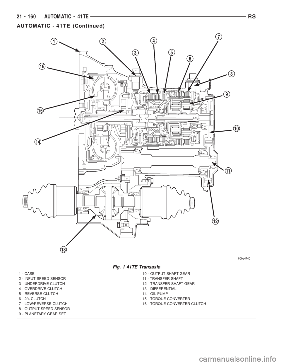
Fig. 1 41TE Transaxle
1 - CASE
2 - INPUT SPEED SENSOR
3 - UNDERDRIVE CLUTCH
4 - OVERDRIVE CLUTCH
5 - REVERSE CLUTCH
6 - 2/4 CLUTCH
7 - LOW/REVERSE CLUTCH
8 - OUTPUT SPEED SENSOR
9 - PLANETARY GEAR SET10 - OUTPUT SHAFT GEAR
11 - TRANSFER SHAFT
12 - TRANSFER SHAFT GEAR
13 - DIFFERENTIAL
14 - OIL PUMP
15 - TORQUE CONVERTER
16 - TORQUE CONVERTER CLUTCH
21 - 160 AUTOMATIC - 41TERS
AUTOMATIC - 41TE (Continued)