manual radio set CHRYSLER VOYAGER 2001 Service Manual
[x] Cancel search | Manufacturer: CHRYSLER, Model Year: 2001, Model line: VOYAGER, Model: CHRYSLER VOYAGER 2001Pages: 4284, PDF Size: 83.53 MB
Page 36 of 4284
section 7.0. This will direct you to the specific test(s)
that must be performed. Active diagnostic trouble
codes for the airbag system are not permanent and
will change the moment the reason for the code is
corrected. In certain test procedures within this
manual, diagnostic trouble codes are used as a
diagnostic tool.
3.1.9 ACTIVE CODES
The code becomes active as soon as the malfunc-
tion is detected or key-on, whichever occurs first. An
active trouble code indicates an on-going malfunc-
tion. This means that the defect is currently there
every time the airbag control module checks that
circuit or component. It is impossible to erase an
active code. Active codes automatically erase by
themselves when the reason for the code has been
corrected. With the exception of the warning lamp
trouble codes or malfunctions, when a malfunction
is detected, the airbag lamp remains lit for a mini-
mum of 12 seconds or as long as the malfunction is
present.
3.1.10 STORED CODES
Airbag codes are automatically stored in the
ORC's memory as soon as the malfunction is de-
tected. The exception is the Loss of Ignition Run
Only code which is an active code only. A stored code
indicates there was an active code present at some
time. However, the code currently may not be
present as an active code, although another code
could be active. When a trouble code occurs, the
airbag warning indicator illuminates for 12 seconds
minimum (even if the problem existed for less than
12 seconds). The code is stored, along with the time
in minutes it was active, and the number of times
the ignition has been cycled since the problem was
last detected. The minimum time shown for any
code will be one minute, even if the code was
actually present for less than one minute. Thus, the
time shown for a code will be one minute, even if the
code was actually present for less than one minute.
Thus, the time shown for a code that was present
for two minutes 13 seconds, for example, would be
three minutes. If a malfunction is detected a diag-
nostic trouble code is stored and will remain stored.
When and if the malfunction ceases to exist, an
ignition cycle count will be initiated for that code. If
the ignition cycle count reaches 100 without a
reoccurrence of the same malfunction, the diagnos-
tic trouble code is erased and that ignition cycle
counter is reset to zero. If the malfunction reoccurs
before the count reaches 100, then the ignition cycle
counter will be reset and diagnostic trouble code
will continue to be a stored code. If a malfunction is
not active while performing a diagnostic test proce-
dure, the active code diagnostic test will not locatethe source of the problem. In this case, the stored
code can indicate an area to inspect. If no obvious
problems are found, erase stored codes, and with
the ignition on wiggle the wire harness and connec-
tors, rotate the steering wheel from stop to stop.
Recheck for codes periodically as you work through
the system. This procedure may uncover a malfunc-
tion that is difficult to locate.
3.2 AUDIO SYSTEM
The following radios are all on the PCI Bus
system - RBB, RBK, RAZ, RAD, RBT, and RBY. The
remaining radio also available, the RAS, is NOT on
the PCI Bus. The PCI Bus inputs into the radio are
used for VF dimming, remote steering wheel con-
trols and cabin EQ preference. PCI Bus outputs
from the radio are used for the Name Brand
Speaker (NBS) relay activation, as well as cabin EQ
preference.
The RBB and RBK radios have the capability of
containing multiple vehicle unique equalization
curves (cabin EQ preferences) within the radio.
These curves will reside in the radio's flash memory.
The radio is capable of storing up to 20 unique
equalization curves. The latent curves can be se-
lected via the Front Control Module transmitting a
PCI Bus message to the radio in response to a radio
request for equalization message. Upon receipt of a
valid equalization select message response, the ra-
dio will switch to output the corresponding equal-
ization curve.
All the radios, except the RAS, are capable of
displaying faults and allowing certain actuation
tests through the use of the DRBIIIt. When at-
tempting to perform PCI Bus diagnostics, the first
step is to identify the radio in use in the vehicle.
When trouble shooting output shorts or ªoutputº
error messages, the following applies:
On radios without an external amplifier, the term
output refers to the path between the radio and the
speaker. This type of circuit can be monitored all
the way through the speaker connections by the
radio assembly. When the radio displays a shorted
output DTC with this type of system, the speaker,
radio, or wiring could be at fault. The output DTC
could refer to the front or rear output or a left or
right output. The reason for the difference is the
pairing of the output sections of the radio. Some are
paired left and right, others are paired front and
rear.
On radios with an external amplifier, the term
ªoutputº refers to the circuit between the radio
connector and the amplifier. The radio is capable of
monitoring only this portion and can tell nothing
about the circuit between the amplifier and the
speakers. Consequently, a shorted output DTC on
7
GENERAL INFORMATION
Page 44 of 4284
Front and rear blower relay
The blower control switch is part of the Automatic
Temperature Control (ATC) or A/C-Heater Control
Module, (Manual Temp). When the blower switch is
turned on, the ATC or A/C-Heater Control Module
sends a PCI Bus message to the FCM. The front and
rear blower relay is then powered through low side
control on pin 30 of the FCM. The relay provides the
high side to the blower motor, and the blower speed
is governed through low side control in the ATC or
A/C-Heater Control Module. This circuit is electron-
ically controlled and continuously monitored for
malfunctions.
Name Brand Speakers (NBS) relay
The NBS relay operates through the vehicle bus
interface between the radio and the FCM. When the
radio is turned on, the radio sends a PCI Bus
message to the FCM. The NBS relay is then pow-
ered on through low side control on pin 11 of the
FCM. The relay supplies power to the amplified
speaker, and ground is supplied through the radio.
This circuit is electronically controlled and contin-
uously monitored for malfunctions.
Electronic Back Light (EBL) relay
The rear defrost switch is part of the Automatic
Temperature Control or A/C-Heater Control Module
(Manual Temp). When the ignition switch is in the
RUN position and the rear defrost switch is turned
on, the ATC or A/C-Heater Control Module sends a
PCI Bus message to the FCM. The EBL run only
relay is then powered through low side control on
pin 31 of the FCM. The relay provides the high side
to the rear window defrost grid, and ground is
attached to the vehicle body. The FCM will only
allow the rear defrost to operate in the RUN posi-
tion. This circuit is electronically controlled and
continuously monitored for malfunctions.
Cabin Heater Relay
When the ignition is in Run, the FCM monitors
the PCI bus for the Cabin Heater Activation re-
quest. The A/C ± Heater Control Module initiates
this request only when all conditions for Cabin
Heater activation are favorable. The request carries
the status bit that the FCM requires to activate its
Cabin Heater Assist Control output. This output is
a low side driver (coming from FCM pin 15) which
supplies a ground signal to the Cabin Heater (pin
5). When the Cabin Heater receives this ground
signal input, it interprets this as an activation
signal. The FCM low side driver is also capable of
diagnostic sensing. The driver will sense an open
circuit when the driver is off, and will sense a short
to voltage when the driver is on. The FCM will set
DTCs for both of these types of faults. For addi-
tional information, refer to Cabin Heater under
General Information and Diagnostic Procedures in
the manual.3.8.3 ELECTRICAL INPUTS
Headlamp battery supplies1&2Ð12 volt
input on pins 1 and 2. Battery supply voltage for
switching headlamp circuits only.
Module battery supply Ð12 volt input on pin 9.
Battery supply voltage for all other FCM opera-
tions.
Power ground ÐGround source on pin 8 for all
FCM operations.
Ignition switch RUN or START position status
Ð12 volt input on pin 37. Allows the FCM to
determine the ignition switch status for related
FCM operations.
Ignition switch START only status Ð12 volt
input on pin 19. Allows the FCM to discriminate
between RUN/START input and START for related
FCM operations.
PCI Bus ÐApproximately 7.5 volt input on pin 22.
Allows the FCM to communicate with other mod-
ules on the vehicle bus.
Stop lamp Switch status Ð12 volt input on pin
44. Provides for brake shift interlock function.
Horn Switch ÐGround input on pin 17. Primary
means for engaging the horn.
Back-up switch ÐGround input on pin 39. Input
is converted to a PCI Bus status message for use by
other modules.
Wiper park switch ÐGround input on pin 16.
Used to determine park placement of wipers. Also
used as feedback to FCM to determine correct
operating mode of wipers.
Washer fluid level switch ÐGround input to
pull-up on pin 18. Ground is switched into the
circuit when washer bottle fluid level is low.
Brake fluid level switch ÐGround input to
pull-up on pin 36. Ground is switched into the
circuit when brake fluid level is low.
Ambient temperature sensor ÐResistive input
to pull-up on pin 25. Corresponding voltage level is
converted to a PCI Bus message for use by other
modules on the bus.
Right park lamp outage Ð12 volt input on pin
21. Used to determine if right park lamp circuit is
operating properly.
Left park lamp outage Ð12 volt input on pin 41.
Used to determine if left park lamp circuit is
operating properly.
Battery IOD Ð12 volt input on pin 20. The FCM
enters a low power consumption mode when the
ignition is turned OFF. This low current draw
battery supply keeps the microprocessor function-
ing in the low power mode.
Battery (+) connection detection Ð12 volt
input on pin 38. The battery connection on the PDC
incorporates the use of an internal switch to deter-
mine if the connector is properly mated and the
Connector Positive Assurance (CPA) is engaged. If
15
GENERAL INFORMATION
Page 51 of 4284
On vehicles equipped with AutoStick, the display
includes an O/D OFF indicator that is illuminated
when the driver presses the Overdrive Off button
on the transaxle shifter.
3.11.1 INSTRUMENT CLUSTER SELF TEST
1. Depress and hold the Odometer Reset button.
2. Turn the ignition switch to the RUN/START
position.
3. Release the Odometer reset button.
The Instrument Cluster will illuminate all indi-
cators and step the gauges through several calibra-
tion points. Also, the odometer will display any
stored codes that may have set.
3.11.2 MESSAGE CENTER
The Message Center is located above the brow of
the Instrument Cluster. It houses the following
warning indicators: Check Engine/Service Engine
Soon, high beam, left and right turn signals, Secu-
rity Alarm Set, and low oil pressure. On base
models equipped with the three-speed transaxle,
these indicators appear in the face of the cluster.
The Security Alarm set indicator is a red circle.
Activation of Instrument Cluster indicators is
coordinated with indicators in the message center
and EVIC to avoid redundancy. A revised safety
standard now requires that the seat belt warning
lamp in the Instrument Cluster remain lit if the
driver seat belt is not buckled. A headlamp out ISO
indicator has been added to the Instrument Cluster
to alert the driver when a headlamp is not function-
ing.
3.12 INTERIOR LIGHTING
3.12.1 COURTESY LAMP CONTROL
The body controller has direct control over all of
the vehicle's courtesy lamps. The body computer
will illuminate the courtesy lamps under any of the
following conditions:
1. Any door ajar and courtesy lamp switch on the
headlamp switch is not in the dome off position.
2. The courtesy lamp switch on the headlamp
switch is in the dome on position.
3. A Remote Keyless Entry unlock message is re-
ceived.
4. Driver door unlocked with key (with VTSS only).
3.12.2 ILLUMINATED ENTRY
Illuminated entry will be initiated when the cus-
tomer enters the vehicle by unlocking the doors
with the key fob, or with the key if the vehicle is
equipped with vehicle theft alarm. Upon exiting thevehicle, if the lock button is pressed with a door
open, illuminated entry will cancel when the door
closes. If the doors are closed and the ignition
switch is turned on, the illuminated entry also
cancels. The illuminated entry feature will not
operate if the courtesy lamp switch is in the dome
off position.
3.12.3 INTERIOR LIGHTING BATTERY
SAVER
If any of the interior lamps are left on after the
ignition is turned off, the BCM will turn them off
after 8 minutes. To return to normal operation, the
courtesy lamps will operate after the dome lamp
switch or door ajar switch changes state. The glove
box and switched reading lamps require that the
ignition be turned to the on/acc position.
3.13 MEMORY SYSTEM
The memory system consists of power driver 's
seat, power mirrors and radio presets. The Memory
Seat/Mirror Module (MSMM) is located under the
driver 's seat. It receives input from the following:
driver 's manual 8-way seat switch, driver 's seat
position sensors, PCI bus circuits, and the power
mirror sensors. The module uses these inputs to
perform the following functions: position the driv-
er 's memory seat, both exterior mirrors (during
recalls), and send/receive the memory system infor-
mation over the PCI bus.
The Memory Set Switch is wired to the Body
Control Module (BCM). When a button (either #1 or
#2) is pressed on the set switch causes the to BCM
send a message to the MSMM which in turn sends
a motion status messages to the BCM. If the BCM
receives no motion from the MSMM it will send a
recall message to the MSMM and radio (once igni-
tion is in run or accessory). The MSMM will in turn
position the drivers seat, both mirrors along with
recalling the radio presets. If the drivers seat or
either exterior mirror is inoperative from its own
respective switches, use the service information
and schematic to diagnose the problem. This man-
ual addresses the memory problems only and it is
assumed there is not a basic component failure.
3.13.1 POWER SEAT
The memory power seat provides the driver with
2 position settings for the driver 's seat. Each power
seat motor is connected to the MSMM with two
motor drive circuits. Each circuit is switched be-
tween battery and ground. By being able to bi-
directionally drive the circuits, the MSMM controls
the movement of the motors based on input from
the power seat switch or from the position sensors
when performing a memory recall. Each motor
22
GENERAL INFORMATION
Page 1222 of 4284
sponder ID message to the SKIM. The SKIM com-
pares the transponder ID message to the available
valid key codes in SKIM memory (8 key maximum
at any one time). After validating the ignition key,
the SKIM sends a PCI Bus message called a seed
request to the ECM, then waits for the ECM re-
sponse. If the ECM does not respond, the SKIM will
send the seed request again. After three failed
attempts, the SKIM will stop sending the seed
request and store a trouble code in memory. If the
ECM sends a seed response, the SKIM sends a
valid/invalid key message to the ECM. This is an
encrypted message that is generated using the
following:
VIN - Vehicle Identification Number.
Seed - This is a random number that is generated
by the ECM at each ignition key cycle.
The VIN and seed are two variables used in the
rolling code algorithm that encrypts the valid/
invalid key message. The ECM uses the rolling code
algorithm to receive, decode and respond to the
valid/invalid key message sent by the SKIM. After
sending the valid/invalid key message, the SKIM
waits 3.5 seconds for an ECM status message from
the ECM. If the ECM does not respond with a valid
key message to the SKIM, a fault is detected and a
code is stored.
The SKIS incorporates a warning lamp located in
the information center. The lamp receives switched
ignition voltage and is hardwired to the body con-
trol module. The lamp is actuated when the SKIM
sends a PCI Bus message to the body control
module requesting the lamp on. The body control
module then provides the ground for the lamp.
The SKIM will request lamp operation for the
following:
± bulb check at ignition on
± to alert the vehicle operator to a SKIS malfunc-
tion
± when the SKIM is in customer key programming
mode
For all faults except transponder faults the lamp
remains on steady. In the event of a transponder
fault the lamp will flash at a rate of 1Hz (once per
second). If a fault is present, the lamp will remain
on or flashing for the complete ignition cycle. If a
fault is stored in SKIM memory which prevents the
system from operating properly, the ECM will allow
the engine to start and idle for 2 seconds then stall.
This may occur up to six times. After the sixth
attempt, the ECM disables the starter relay until
the fault is corrected.
3.3 DIAGNOSTIC TROUBLE CODES
Each diagnostic trouble code (DTC) is diagnosed
by following a specific procedure. The diagnostic
test procedure contains step-by-step instruction fordetermining the cause of the DTC as well as no
trouble code problems. It is not necessary to per-
form all of the tests in this book to diagnose an
individual code.
Always begin diagnosis by reading the DTC's
using the DRBIIIt.
3.3.1 HARD CODE
A DTC that comes back within one cycle of the
ignition key is a hard code. This means that the
problem is current every time the ECM/SKIM
checks that circuit or function. Procedures in this
manual verify if the DTC is a hard code at the
beginning of each test. When the fault is not a hard
code, an intermittent test must be performed.
NOTE: If the DRBIIItdisplays faults for multiple
components (i.e. ECT, VSS, Oil Temp sensors) iden-
tify and check the shared circuits for possible prob-
lems before continuing (i.e. sensor grounds or 5-volt
supply circuits). Refer to the appropriate schematic
to identify shared circuits.
3.3.2 INTERMITTENT CODE
A DTC that is not current every time the ECM/
SKIM checks the circuit or function is an intermit-
tent code. Most intermittent DTCs are caused by
wiring or connector problems. Problems that come
and go like this are the most difficult to diagnose;
they must be looked for under specific conditions
that cause them. The following checks may assist
you in identifying a possible intermittent problem.
²Visually inspect the related wire harness connec-
tors. Look for broken, bent, pushed out, or cor-
roded terminals.
²Visually inspect the related wire harness. Look
for chafed, pierced, or partially broken wire.
²Refer to hotlines or technical service bulletins
that may apply.
NOTE: Electromagnetic (radio) interference can
cause an intermittent system malfunction. This
interference can interrupt communication between
the ignition key transponder and the SKIM.
3.3.3 ECM DIAGNOSTIC TROUBLE CODES
IMPORTANT NOTE:Before replacing the ECM
for a failed driver, control circuit or ground circuit,
be sure to check the related component/circuit in-
tegrity for failures not detected due to a double fault
in the circuit. Most ECM driver/control circuit fail-
ures are caused by internal failures to components
(i.e. relays and solenoids) and shorted circuits (i.e.
sensor pull-ups, drivers and ground circuits). These
faults are difficult to detect when a double fault has
occurred and only one DTC has set.
If the DRB displays faults for multiple compo-
nents (i.e. VSS, ECT, Batt Temp, etc.), identify and
3
GENERAL INFORMATION
Page 1805 of 4284
AUDIO
TABLE OF CONTENTS
page page
AUDIO
DESCRIPTION............................1
OPERATION.............................1
DIAGNOSIS AND TESTING..................1
ANTENNA BODY & CABLE
DESCRIPTION............................3
OPERATION.............................3
DIAGNOSIS AND TESTING..................3
REMOVAL...............................4
INSTALLATION............................4
CD CHANGER
DESCRIPTION............................6
OPERATION.............................6
REMOVAL...............................6
INSTALLATION............................6
CHOKE
DIAGNOSIS AND TESTING..................6
D-PILLAR SPEAKER
REMOVAL...............................6
INSTALLATION............................7
DASH PANEL SPEAKER
REMOVAL...............................7INSTALLATION............................7
DOOR MOUNTED SPEAKER
REMOVAL...............................7
INSTALLATION............................7
QUARTER PANEL SPEAKER
REMOVAL...............................8
INSTALLATION............................8
RADIO
DIAGNOSIS AND TESTING..................8
REMOVAL...............................9
INSTALLATION............................9
RADIO NOISE SUPPRESSION COMPONENTS
DESCRIPTION............................9
OPERATION.............................9
REMOTE SWITCHES
DESCRIPTION...........................10
OPERATION.............................10
DIAGNOSIS AND TESTING.................11
REMOVAL..............................11
INSTALLATION...........................12
AUDIO
DESCRIPTION
There are four different system combinations avail-
able on the RS models. The available radio options
are:
²AM/FM Cassette
²AM/FM Compact Disc with Compact Disc
Changer
²AM/FM Cassette with single Compact Disc
Player
²AM/FM Cassette with Compact Disc Changer
All factory installed radio receivers are stereo Elec-
tronically Tuned Radios (ETR) and include and elec-
tronic digital clock function.
OPERATION
Operating instructions for the factory installed
audio systems can be found in the Owner's Manual
provided with this vehicle.
DIAGNOSIS AND TESTING
WARNING:
ON VEHICLES EQUIPPED WITH AIRBAGS, REFER
TO ELECTRICAL, RESTRAINTS BEFORE ATTEMPT-
ING ANY STEERING WHEEL, STEERING COLUMN,
OR INSTRUMENT PANEL COMPONENT DIAGNOSIS
OR SERVICE. FAILURE TO TAKE THE PROPER
PRECAUTIONS COULD RESULT IN ACCIDENTAL
AIRBAG DEPLOYMENT AND POSSIBLE PERSONAL
INJURY.
RSAUDIO8A-1
Page 1814 of 4284
REMOTE SWITCHES
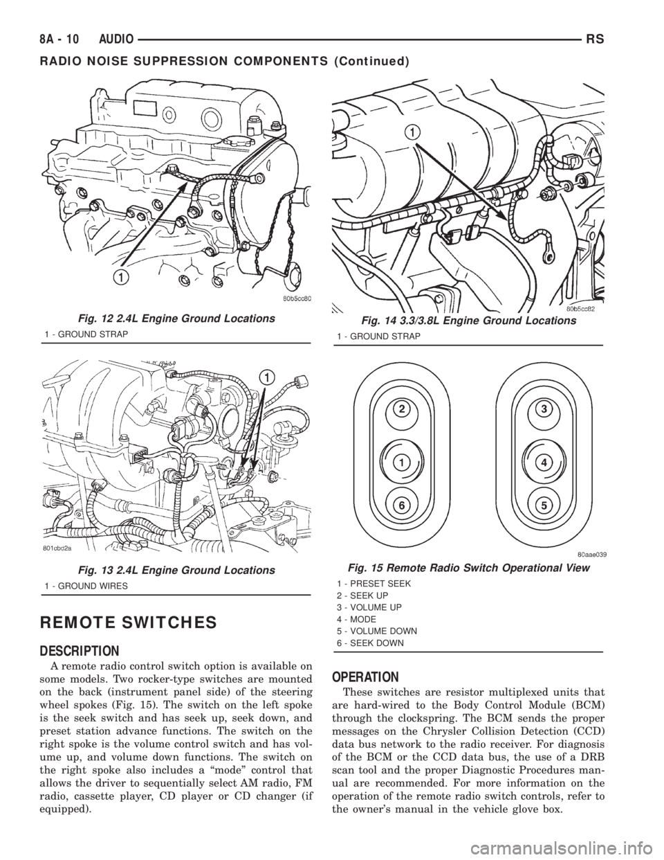
DESCRIPTION
A remote radio control switch option is available on
some models. Two rocker-type switches are mounted
on the back (instrument panel side) of the steering
wheel spokes (Fig. 15). The switch on the left spoke
is the seek switch and has seek up, seek down, and
preset station advance functions. The switch on the
right spoke is the volume control switch and has vol-
ume up, and volume down functions. The switch on
the right spoke also includes a ªmodeº control that
allows the driver to sequentially select AM radio, FM
radio, cassette player, CD player or CD changer (if
equipped).
OPERATION
These switches are resistor multiplexed units that
are hard-wired to the Body Control Module (BCM)
through the clockspring. The BCM sends the proper
messages on the Chrysler Collision Detection (CCD)
data bus network to the radio receiver. For diagnosis
of the BCM or the CCD data bus, the use of a DRB
scan tool and the proper Diagnostic Procedures man-
ual are recommended. For more information on the
operation of the remote radio switch controls, refer to
the owner's manual in the vehicle glove box.
Fig. 12 2.4L Engine Ground Locations
1 - GROUND STRAP
Fig. 13 2.4L Engine Ground Locations
1 - GROUND WIRES
Fig. 14 3.3/3.8L Engine Ground Locations
1 - GROUND STRAP
Fig. 15 Remote Radio Switch Operational View
1 - PRESET SEEK
2 - SEEK UP
3 - VOLUME UP
4 - MODE
5 - VOLUME DOWN
6 - SEEK DOWN
8A - 10 AUDIORS
RADIO NOISE SUPPRESSION COMPONENTS (Continued)
Page 1815 of 4284
DIAGNOSIS AND TESTING
WARNING:
ON VEHICLES EQUIPPED WITH AIRBAGS, REFER
TO ELECTRICAL, RESTRAINTS BEFORE ATTEMPT-
ING ANY STEERING WHEEL, STEERING COLUMN,
OR INSTRUMENT PANEL COMPONENT DIAGNOSIS
OR SERVICE. FAILURE TO TAKE THE PROPER
PRECAUTIONS COULD RESULT IN ACCIDENTAL
AIRBAG DEPLOYMENT AND POSSIBLE PERSONAL
INJURY.
(1) Disconnect and isolate the battery negative
cable. Wait two minutes for the airbag system capac-
itor to discharge before further service.
(2) Remove the remote radio switch(es) from the
steering wheel. (Refer to 8 - ELECTRICAL/AUDIO/
REMOTE SWITCHES - REMOVAL).
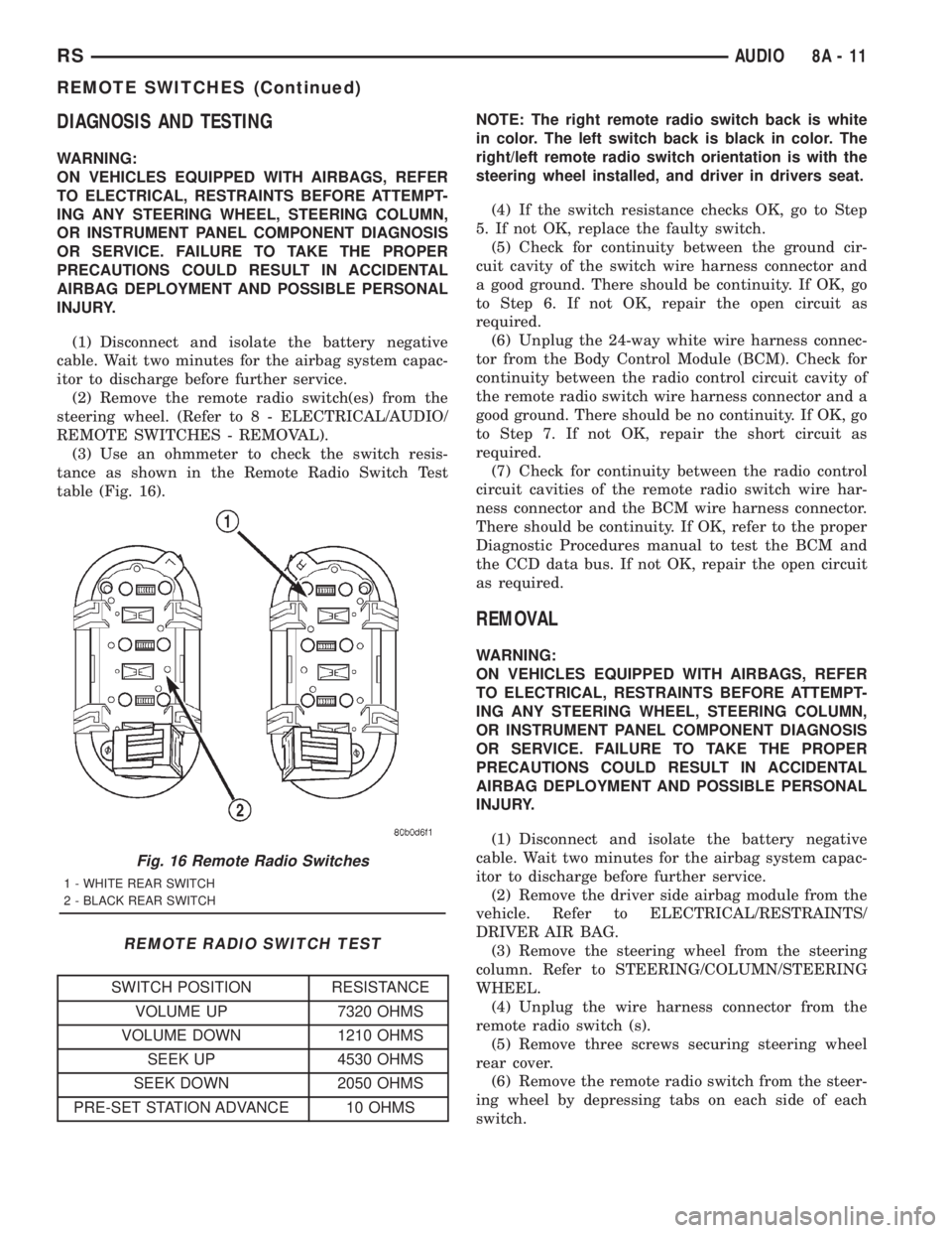
(3) Use an ohmmeter to check the switch resis-
tance as shown in the Remote Radio Switch Test
table (Fig. 16).
REMOTE RADIO SWITCH TEST
SWITCH POSITION RESISTANCE
VOLUME UP 7320 OHMS
VOLUME DOWN 1210 OHMS
SEEK UP 4530 OHMS
SEEK DOWN 2050 OHMS
PRE-SET STATION ADVANCE 10 OHMSNOTE: The right remote radio switch back is white
in color. The left switch back is black in color. The
right/left remote radio switch orientation is with the
steering wheel installed, and driver in drivers seat.
(4) If the switch resistance checks OK, go to Step
5. If not OK, replace the faulty switch.
(5) Check for continuity between the ground cir-
cuit cavity of the switch wire harness connector and
a good ground. There should be continuity. If OK, go
to Step 6. If not OK, repair the open circuit as
required.
(6) Unplug the 24-way white wire harness connec-
tor from the Body Control Module (BCM). Check for
continuity between the radio control circuit cavity of
the remote radio switch wire harness connector and a
good ground. There should be no continuity. If OK, go
to Step 7. If not OK, repair the short circuit as
required.
(7) Check for continuity between the radio control
circuit cavities of the remote radio switch wire har-
ness connector and the BCM wire harness connector.
There should be continuity. If OK, refer to the proper
Diagnostic Procedures manual to test the BCM and
the CCD data bus. If not OK, repair the open circuit
as required.
REMOVAL
WARNING:
ON VEHICLES EQUIPPED WITH AIRBAGS, REFER
TO ELECTRICAL, RESTRAINTS BEFORE ATTEMPT-
ING ANY STEERING WHEEL, STEERING COLUMN,
OR INSTRUMENT PANEL COMPONENT DIAGNOSIS
OR SERVICE. FAILURE TO TAKE THE PROPER
PRECAUTIONS COULD RESULT IN ACCIDENTAL
AIRBAG DEPLOYMENT AND POSSIBLE PERSONAL
INJURY.
(1) Disconnect and isolate the battery negative
cable. Wait two minutes for the airbag system capac-
itor to discharge before further service.
(2) Remove the driver side airbag module from the
vehicle. Refer to ELECTRICAL/RESTRAINTS/
DRIVER AIR BAG.
(3) Remove the steering wheel from the steering
column. Refer to STEERING/COLUMN/STEERING
WHEEL.
(4) Unplug the wire harness connector from the
remote radio switch (s).
(5) Remove three screws securing steering wheel
rear cover.
(6) Remove the remote radio switch from the steer-
ing wheel by depressing tabs on each side of each
switch.
Fig. 16 Remote Radio Switches
1 - WHITE REAR SWITCH
2 - BLACK REAR SWITCH
RSAUDIO8A-11
REMOTE SWITCHES (Continued)
Page 1869 of 4284
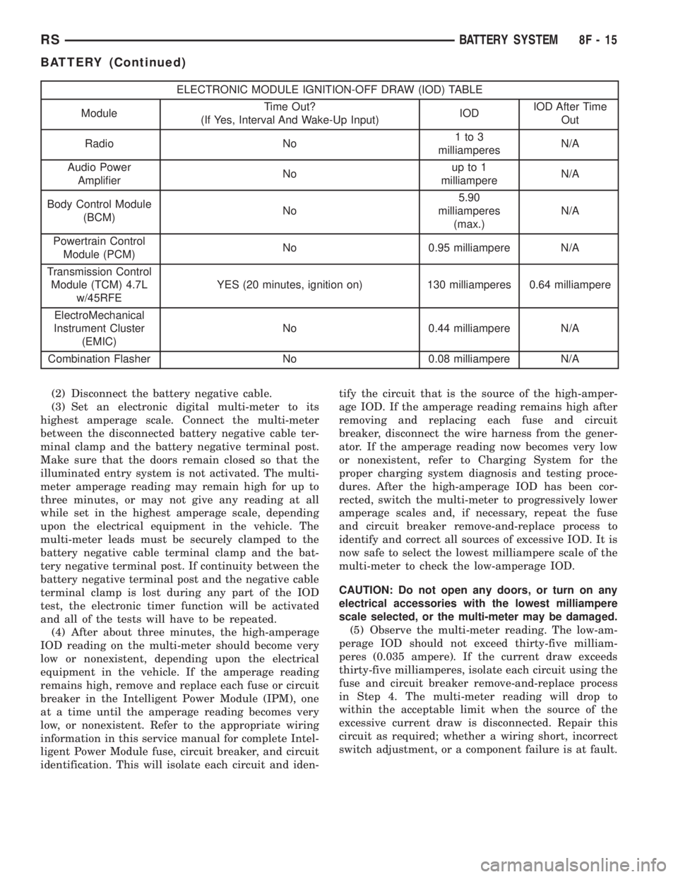
ELECTRONIC MODULE IGNITION-OFF DRAW (IOD) TABLE
ModuleTime Out?
(If Yes, Interval And Wake-Up Input)IODIOD After Time
Out
Radio No1to3
milliamperesN/A
Audio Power
AmplifierNoup to 1
milliampereN/A
Body Control Module
(BCM)No5.90
milliamperes
(max.)N/A
Powertrain Control
Module (PCM)No 0.95 milliampere N/A
Transmission Control
Module (TCM) 4.7L
w/45RFEYES (20 minutes, ignition on) 130 milliamperes 0.64 milliampere
ElectroMechanical
Instrument Cluster
(EMIC)No 0.44 milliampere N/A
Combination Flasher No 0.08 milliampere N/A
(2) Disconnect the battery negative cable.
(3) Set an electronic digital multi-meter to its
highest amperage scale. Connect the multi-meter
between the disconnected battery negative cable ter-
minal clamp and the battery negative terminal post.
Make sure that the doors remain closed so that the
illuminated entry system is not activated. The multi-
meter amperage reading may remain high for up to
three minutes, or may not give any reading at all
while set in the highest amperage scale, depending
upon the electrical equipment in the vehicle. The
multi-meter leads must be securely clamped to the
battery negative cable terminal clamp and the bat-
tery negative terminal post. If continuity between the
battery negative terminal post and the negative cable
terminal clamp is lost during any part of the IOD
test, the electronic timer function will be activated
and all of the tests will have to be repeated.
(4) After about three minutes, the high-amperage
IOD reading on the multi-meter should become very
low or nonexistent, depending upon the electrical
equipment in the vehicle. If the amperage reading
remains high, remove and replace each fuse or circuit
breaker in the Intelligent Power Module (IPM), one
at a time until the amperage reading becomes very
low, or nonexistent. Refer to the appropriate wiring
information in this service manual for complete Intel-
ligent Power Module fuse, circuit breaker, and circuit
identification. This will isolate each circuit and iden-tify the circuit that is the source of the high-amper-
age IOD. If the amperage reading remains high after
removing and replacing each fuse and circuit
breaker, disconnect the wire harness from the gener-
ator. If the amperage reading now becomes very low
or nonexistent, refer to Charging System for the
proper charging system diagnosis and testing proce-
dures. After the high-amperage IOD has been cor-
rected, switch the multi-meter to progressively lower
amperage scales and, if necessary, repeat the fuse
and circuit breaker remove-and-replace process to
identify and correct all sources of excessive IOD. It is
now safe to select the lowest milliampere scale of the
multi-meter to check the low-amperage IOD.
CAUTION: Do not open any doors, or turn on any
electrical accessories with the lowest milliampere
scale selected, or the multi-meter may be damaged.
(5) Observe the multi-meter reading. The low-am-
perage IOD should not exceed thirty-five milliam-
peres (0.035 ampere). If the current draw exceeds
thirty-five milliamperes, isolate each circuit using the
fuse and circuit breaker remove-and-replace process
in Step 4. The multi-meter reading will drop to
within the acceptable limit when the source of the
excessive current draw is disconnected. Repair this
circuit as required; whether a wiring short, incorrect
switch adjustment, or a component failure is at fault.
RSBATTERY SYSTEM8F-15
BATTERY (Continued)
Page 1978 of 4284
OPERATION
The Compass Mini-Trip Computer (CMTC), Com-
pass Temperature (CT) module in the overhead con-
sole has buttons used to select various functions. The
CMTC, CT selector buttons will not operate until the
ignition is in the RUN position.
When the ignition switch is first turned to the
RUN position the CMTC, CT display;
²Blanks momentarily
²
All segments of the VFD will light for one second
²Blanks momentarily
²Returns to the last mode setting selected before
the ignition was last switched OFF.
DIAGNOSIS & TESTING - COMPASS MINI-TRIP
COMPUTER
Compass Mini-Trip Computer (CMTC) and Com-
pass Temperature (CT) data is obtained from the
Body Control Module (BCM) on the J1850 Data Bus
circuit. The CMTC and CT will display dashes (- -)
for any of the screens it did not receive the bus mes-
sages. The label corresponding to the missing infor-
mation will be lit. If no compass mini-trip computer
data is displayed, check the J1850 Data Bus circuit
communications and the BCM. If the brightness level
is improper check the J1850 Data Bus circuit.
The DRB IIItis recommended for checking the
J1850 Data Bus circuit and the BCM. Perform the
CMTC, CT self diagnosis before replacing the CMTC
or CT module.
REMOVAL
(1) Disconnect and isolate the battery negative
cable.
(2) Remove overhead console. Refer to Overhead
Console Removal and Installation in this section(Re-
fer to 8 - ELECTRICAL/OVERHEAD CONSOLE -
REMOVAL) .
(3) Remove the screws holding Compass Mini-Trip
Computer module in the overhead console.
(4) Remove CMTC module from console assembly.
INSTALLATION
(1) Position the compass mini-trip computer mod-
ule in the overhead console.
(2) Install the ten screws holding the compass
mini-trip computer module in the overhead console.
(3) Install the overhead console. Refer to Overhead
Console Removal and Installation in this section.
(4) Connect the battery negative cable.
NOTE: If a new module has been installed, the com-
pass will have to be calibrated and the variance set.
Refer to Compass Variation Adjustment and Com-
pass Calibration in the Service Procedures section
of this group for the procedures.
UNIVERSAL TRANSMITTER
DESCRIPTION
On some RS models a Homelinkttransceiver is
standard factory-installed equipment. The Homelinkt
transceiver is integral to the Electronic Vehicle Infor-
mation Center (EVIC) and the Compass Mini-Trip
Computer (CMTC), which is located in the overhead
console. The only visible component of the Homelinkt
are the three transmitter push buttons centered
between the modules push buttons located just rear-
ward of the display screen in the overhead console.
The three Homelinkttransmitter push buttons are
identified with one, two or three light indicators so
that they be easily identified by sight or by feel.
Each of the three Homelinkttransmitter push but-
tons controls an independent radio transmitter chan-
nel. Each of these three channels can be trained to
transmit a different radio frequency signal for the
remote operation of garage door openers, motorized
gate openers, home or office lighting, security sys-
tems or just about any other device that can be
equipped with a radio receiver in the 286 to 399
MegaHertz (MHz) frequency range for remote opera-
tion. The Homelinktis capable of operating systems
using either rolling code or non-rolling code technol-
ogy.
The electronics module displays messages and a
small house-shaped icon with one, two or three dots
corresponding to the three transmitter buttons to
indicate the status of the Homelinkt. The EVIC mes-
sages are:
²Cleared Channels- Indicates that all of the
transmitter codes stored in the Homelinkthave been
successfully cleared.
²Training- Indicates that the Homelinktis in
its transmitter learning mode.
²Trained- Indicates that the Homelinkthas
successfully acquired a new transmitter code.
²Transmit- Indicates that a trained Homelinkt
transmitter button has been depressed and that the
Homelinktis transmitting.
The Homelinktcannot be repaired, and is avail-
able for service only as a unit with the EVIC or
CMTC modules. If any of these components is faulty
or damaged, the complete EVIC or CMTC module
must be replaced.
OPERATION
The Homelinktoperates on a non-switched source
of battery current so the unit will remain functional,
regardless of the ignition switch position. For more
information on the features, programming procedures
and operation of the Homelinkt, see the owner's
manual in the vehicle glove box.
8M - 10 OVERHEAD CONSOLERS
COMPASS/MINI-TRIP COMPUTER (Continued)
Page 2030 of 4284
A eight-way power seat is standard on highline
models and optional on others. This option includes a
six-way adjustable seat cushion track and a two-way
power seat back.
The eight-way power seat is also available with the
heated seat and memory seat system that automati-
cally positions the power seat for two different driv-
ers. Refer toHeated Seat Systemfor more
information on the heated seat option. Refer toMem-
ory Systemin the Memory System section of this
group for more information on the memory system.
The power seat system includes the following com-
ponents:
²Power seat recliner
²Power seat switch
²Power seat track.
The power seat system with memory and heated
seat options includes the following components:
²Power seat recliner
²Power seat switch
²Power seat track.
²Memory Heated Seat Module (MHSM)
²Memory set switch
²Heated seat switch
²Electronic Vehicle Information Center (EVIC)
²Programmable Communications Interface (PCI)
data bus network
Refer to Wiring Diagrams for complete circuit dia-
grams. Following are general descriptions and opera-
tions for the major components in the power seat
system and memory seat system.
DESCRIPTION - MEMORY SEAT SYSTEM
An electronic memory and heated seat system is
available on some models. The memory system is
able to store and recall the driver side power seat
positions (including the power recliner position), and
both outside power mirror positions for two drivers.
For vehicles with a radio and heated / memory seat
system connected to the Programmable Communica-
tions Interface (PCI) data bus network, the memory
system is also able to store and recall radio station
presets for two drivers. The memory system also will
store and recall the last station listened to for each
driver, even if it is not one of the preset stations.
The memory system will automatically return to
all of these settings when the corresponding num-
bered and button of the memory switch on the driver
side seat side shield is depressed, or when the doors
are unlocked using the Remote Keyless Entry (RKE)
transmitter. A customer programmable feature of the
memory system allows the RKE recall of memory fea-
tures to be disabled in cases where there are more
than two drivers of the vehicle.
A Memory Heated Seat Module (MHSM) is used on
some models to control and integrate the many elec-tronic functions and features included in the memory
/ heated seat system.
The memory system includes the following compo-
nents:
²Heated seat switch
²Memory heated seat module (MHSM)
²Memory switch
²Position potentiometers on both outside power
mirrors
²Position potentiometers on the driver side power
seat track and power seat recliner motors.
²Radio receiver (if PCI data bus capable).
Certain functions and features of the memory system
rely upon resources shared with other electronic mod-
ules in the vehicle over the Programmable Communica-
tions Interface (PCI) J1850 data bus network. The PCI
data bus network allows the sharing of sensor informa-
tion. This helps to reduce wire harness complexity,
internal controller hardware, and component sensor cur-
rent loads. At the same time, this system provides
increased reliability, enhanced diagnostics, and allows
the addition of many new feature capabilities. For diag-
nosis of these electronic modules or of the PCI data bus
network, the use of a DRBtscan tool and the proper
Diagnostic Procedures manual are recommended.
The other electronic modules that may affect mem-
ory system operation are as follows:
²Body Control Module (BCM)- Refer toBody
Control Modulein Electronic Control Modules for
more information.
²
Electronic Vehicle Information Center (EVIC)
- Refer toElectronic Vehicle Information Center
in Overhead Console Systems for more information.
²Powertrain Control Module (PCM)- Refer to
Powertrain Control Modulein Electronic Control
Modules for more information.
²Radio Receiver- Refer toRadio Receiverin
Audio Systems for more information.
Refer toHeated Seat Systemfor more informa-
tion on the heated seat system. Refer toRemote
Keyless Entry Systemin Power Lock Systems for
more information on the RKE system. Refer to
Power Mirrorin Power Mirrors for more informa-
tion on the mirror position potentiometers. Refer to
Power Seat TrackandPower Seat Reclinerin
the Power Seat System section of this group for more
information on the driver side power seat position
potentiometers.
Refer toPower Seatin the Contents of Wiring
Diagrams for complete circuit diagrams. Following
are general descriptions of the remaining major com-
ponents in the factory-installed memory system.
OPERATION - POWER SEAT SYSTEM
The power seat system allows the driver and/or
front passenger seating positions to be adjusted elec-
8N - 50 POWER SEATSRS
POWER SEATS (Continued)