ECO mode CHRYSLER VOYAGER 2001 Manual PDF
[x] Cancel search | Manufacturer: CHRYSLER, Model Year: 2001, Model line: VOYAGER, Model: CHRYSLER VOYAGER 2001Pages: 4284, PDF Size: 83.53 MB
Page 1976 of 4284

STANDARD PROCEDURE - ELECTRONIC
VEHICLE INFORMATION CENTER
PROGRAMMING
EVIC PROGRAMMING MODE
Some vehicles are equipped with a Electronic Vehi-
cle Information Center (EVIC) equipped overhead
console. The Electronic Vehicle Information Center
(EVIC) provides the vehicle operator with a user
interface, which allows the selection of several
optional customer programmable electronic features
to suit individual preferences. The EVIC must be
placed into its programming mode in order to view or
change the programmable features. To enter the
EVIC programming mode and to view or change the
selected programmable features options, proceed as
follows:
(1) Turn the ignition switch to the On position.
(2) Depress and release the Menu push button.
The first item in the programmable features menu
list will appear in the EVIC display.
(3) Momentarily depress and release the Menu
push button to step through the programmable fea-
tures list. Each programmable feature and its cur-
rently selected option will appear on the EVIC
display in the sequence shown in the Programmable
Features list that follows.
(4) Momentarily depress and release the Step push
button to step through the available options for the
programmable feature being displayed.
(5) The option that last appears in the display
with a programmable feature before exiting the pro-
gramming mode, becomes the newly selected pro-
grammable feature option.
(6) The EVIC exits the programming mode and
returns to its normal operating mode when the C/T
push button is depressed or when the end of the pro-
grammable features menu list is reached, whichever
occurs first.
PROGRAMMABLE FEATURES
²LANGUAGE?- The options include English,
Francaise, Deutsch, Italiana, or Espanol. The default
is English. All EVIC display nomenclature, including
the trip computer functions, warning messages and
the programmable features appear in the selected
language.
²DISPLAY U.S. OR METRIC?- The options
include U.S. and M. The default is U.S. This feature
toggles the trip computer temperature, fuel economy
and odometer display readings between U.S. and
metric units of measure. It also changes the odome-
ter display in the instrument cluster.
²SERVICE INTV. =- The options include from
1000 to 12000 kilometers in 1000 kilometer incre-
ments (2000 to 7500 miles in 500 mile increments).The default is 12000 kilometers (7500 miles). The
selected distance becomes the interval at which the
Perform Service warning message will be displayed
by the EVIC. If a new distance is selected, a second
programmable feature appears,RESET SERVICE
DISTANCE?- The options include No and Yes. The
default is Yes. When Yes is selected, the accumulated
distance since the last previous Perform Service
warning message will be reset to zero because the
service interval has been changed. When No is
selected, the distance until the next Perform Service
warning message is reduced by the accumulated dis-
tance since the last previous message.
²USE FACTORY SETTINGS?- The options
include Yes and No. The default is Yes. When yes is
selected all the programmable features will return to
there defaults and the rest of the programmable fea-
tures will not be displayed. If No is selected the rest
of the programmable features will be displayed at
there default values. This feature will automatically
return to the Yes default under two conditions. First,
if no programmable features are changed from there
defaults. Second, if all the programmable features
equal there defaults.
²AUTO DOOR LOCKS?- The options include
Yes and No. The default is Yes. When Yes is selected,
all doors and the liftgate lock automatically when
vehicle speed reaches 25 kilometers-per-hour (15
miles-per-hour). If YES is selected, a second program-
mable feature appears,AUTO UNLOCK ON EXIT?
- The options again include Yes and No. The default
is No. When Yes is selected, following each Auto Door
Lock event all doors and the liftgate will automati-
cally unlock when the driver door is opened, if the
vehicle is stopped and the transmission gear selector
is in Park or Neutral. The Auto Door Unlock event
will only occur once following each Auto Door Lock
event.
²REMOTE UNLOCK- The options include
Driver Door 1st and All Doors. The default is Driver
Door 1st. When Diver Door 1st is selected, only the
driver door unlocks when the Unlock button of the
Remote Keyless Entry (RKE) transmitter is
depressed once. The Unlock button of the RKE trans-
mitter must be depressed twice to unlock all doors.
When All Doors is selected, all doors unlock when the
Unlock button of the RKE transmitter is depressed
once.
²REMOTE LINKED TO MEMORY?- This pro-
grammable feature only applies to vehicles equipped
with the optional memory / heated system. The
options include Yes and No. The default is No. When
Yes is selected, the memory system will recall the
Driver 1 or Driver 2 memory settings assigned to the
RKE transmitter being used to unlock the vehicle.
When No is selected, the memory system will only
8M - 8 OVERHEAD CONSOLERS
ELECTRONIC VEHICLE INFO CENTER (Continued)
Page 1977 of 4284

recall memory settings when the Driver 1 or Driver 2
push buttons of the memory switch on the driver side
front door trim panel are depressed.
²SOUND HORN ON LOCK?- The options
include Yes and No. The default is No. When Yes is
selected, a short horn chirp will provide an audible
confirmation when the RKE receiver recognizes a
valid Lock signal from an RKE transmitter. When No
is selected, no horn chirp will occur with the RKE
Lock event. This feature may be selected indepen-
dent of theFLASH LIGHTS WITH LOCKS?pro-
grammable feature.
²FLASH LIGHTS WITH LOCKS?- The options
include Yes and No. The default is Yes. When Yes is
selected, a single flash of the hazard warning lamps
will provide an optical confirmation when the RKE
receiver recognizes a valid Lock signal from an RKE
transmitter, and two flashes of the same lamps will
occur when the RKE receiver recognizes a valid
Unlock signal from an RKE transmitter. When No is
selected, no lamp flash will occur with the RKE Lock
or Unlock event. This feature may be selected inde-
pendent of theSOUND HORN ON LOCK?pro-
grammable feature.
²HEADLAMP DELAY =- The options include
Off, 30 Sec, 60 Sec, and 90 Sec. The default is 90 Sec.
When a time interval is selected, the headlamps will
remain on for that length of time when the head-
lamps are turned off after the ignition is turned off,
or if the Auto mode is selected on vehicles with the
Auto Headlamps option. When Off is selected, the
headlamp delay feature is disabled.
²HEADLAMPS ON WITH WIPERS?- This pro-
grammable feature only applies to vehicles equipped
with the optional Auto Headlamps. The options
include Yes and No. The default is No. When Yes is
selected, the headlamps will turn on automatically
when the windshield wipers are turned on. The head-
lamps will turn off when the wipers are turned off,
as long as the headlamp switch is in the Auto or Off
positions. When No is selected, the headlamps will
only turn on if manually selected or if the Auto mode
is selected and the outside ambient light levels dic-
tate that they should be on.
²POWER ACCESSORY DELAY?- The options
include Yes and No. The default is Yes. When No is
selected, the accessory powered components will turn
off automatically when the ignition key is turned off.
When Yes is selected, the accessory powered compo-
nents will remain on for 45 seconds when the igni-
tion key is turned off.
REMOVAL
(1) Disconnect and isolate the battery negative
cable.(2) Remove overhead console. Refer to Overhead
Console Removal and Installation in this section(Re-
fer to 8 - ELECTRICAL/OVERHEAD CONSOLE -
REMOVAL) .
(3) Remove the ten screws holding the EVIC mod-
ule in the overhead console.
(4) Remove EVIC module from console assembly.
INSTALLATION
(1) Position the EVIC module in the overhead con-
sole.
(2) Install the ten screws holding the EVIC module
in the overhead console.
(3) Install the overhead console. Refer to Overhead
Console Removal and Installation in this section.
(4) Connect the battery negative cable.
NOTE: If a new EVIC module has been installed, the
compass will have to be calibrated and the variance
set. Refer to Compass Variation Adjustment and
Compass Calibration in the Service Procedures sec-
tion of this group for the procedures.
COMPASS/MINI-TRIP
COMPUTER
DESCRIPTION
The Compass Mini-Trip Computer (CMTC) and
Compass Temperature (CT) computer are modules
located in the overhead console. Vehicles are
equipped with either the CMTC or the CT computers
not both. The CMTC is different in the fact that it is
equipped with the mini-trip feature. The CMTC, CT
consists of a electronic control module with a vacuum
fluorescent display (VFD) and function switches. The
CMTC, CT consists of a electronic module that dis-
plays compass, trip computer (CMTC only), and tem-
perature features. Actuating the STEP push button
(CMTC only) will cause the CMTC to change mode of
operation when ignition is ON. Actuating the STEP
push button (CMTC only) will cause the CMTC to
change mode of operation when ignition is ON.
Example:
²Average miles per gallon (ECO)
²Distance to empty (DTE)
²Instant miles per gallon (ECO)
²Trip odometer (ODO)
²Elapsed time (ET)
²Off
Actuating the C/T push button will cause the
CMTC, CT to change to Compass/Temperature dis-
play.
RSOVERHEAD CONSOLE8M-9
ELECTRONIC VEHICLE INFO CENTER (Continued)
Page 1978 of 4284
OPERATION
The Compass Mini-Trip Computer (CMTC), Com-
pass Temperature (CT) module in the overhead con-
sole has buttons used to select various functions. The
CMTC, CT selector buttons will not operate until the
ignition is in the RUN position.
When the ignition switch is first turned to the
RUN position the CMTC, CT display;
²Blanks momentarily
²
All segments of the VFD will light for one second
²Blanks momentarily
²Returns to the last mode setting selected before
the ignition was last switched OFF.
DIAGNOSIS & TESTING - COMPASS MINI-TRIP
COMPUTER
Compass Mini-Trip Computer (CMTC) and Com-
pass Temperature (CT) data is obtained from the
Body Control Module (BCM) on the J1850 Data Bus
circuit. The CMTC and CT will display dashes (- -)
for any of the screens it did not receive the bus mes-
sages. The label corresponding to the missing infor-
mation will be lit. If no compass mini-trip computer
data is displayed, check the J1850 Data Bus circuit
communications and the BCM. If the brightness level
is improper check the J1850 Data Bus circuit.
The DRB IIItis recommended for checking the
J1850 Data Bus circuit and the BCM. Perform the
CMTC, CT self diagnosis before replacing the CMTC
or CT module.
REMOVAL
(1) Disconnect and isolate the battery negative
cable.
(2) Remove overhead console. Refer to Overhead
Console Removal and Installation in this section(Re-
fer to 8 - ELECTRICAL/OVERHEAD CONSOLE -
REMOVAL) .
(3) Remove the screws holding Compass Mini-Trip
Computer module in the overhead console.
(4) Remove CMTC module from console assembly.
INSTALLATION
(1) Position the compass mini-trip computer mod-
ule in the overhead console.
(2) Install the ten screws holding the compass
mini-trip computer module in the overhead console.
(3) Install the overhead console. Refer to Overhead
Console Removal and Installation in this section.
(4) Connect the battery negative cable.
NOTE: If a new module has been installed, the com-
pass will have to be calibrated and the variance set.
Refer to Compass Variation Adjustment and Com-
pass Calibration in the Service Procedures section
of this group for the procedures.
UNIVERSAL TRANSMITTER
DESCRIPTION
On some RS models a Homelinkttransceiver is
standard factory-installed equipment. The Homelinkt
transceiver is integral to the Electronic Vehicle Infor-
mation Center (EVIC) and the Compass Mini-Trip
Computer (CMTC), which is located in the overhead
console. The only visible component of the Homelinkt
are the three transmitter push buttons centered
between the modules push buttons located just rear-
ward of the display screen in the overhead console.
The three Homelinkttransmitter push buttons are
identified with one, two or three light indicators so
that they be easily identified by sight or by feel.
Each of the three Homelinkttransmitter push but-
tons controls an independent radio transmitter chan-
nel. Each of these three channels can be trained to
transmit a different radio frequency signal for the
remote operation of garage door openers, motorized
gate openers, home or office lighting, security sys-
tems or just about any other device that can be
equipped with a radio receiver in the 286 to 399
MegaHertz (MHz) frequency range for remote opera-
tion. The Homelinktis capable of operating systems
using either rolling code or non-rolling code technol-
ogy.
The electronics module displays messages and a
small house-shaped icon with one, two or three dots
corresponding to the three transmitter buttons to
indicate the status of the Homelinkt. The EVIC mes-
sages are:
²Cleared Channels- Indicates that all of the
transmitter codes stored in the Homelinkthave been
successfully cleared.
²Training- Indicates that the Homelinktis in
its transmitter learning mode.
²Trained- Indicates that the Homelinkthas
successfully acquired a new transmitter code.
²Transmit- Indicates that a trained Homelinkt
transmitter button has been depressed and that the
Homelinktis transmitting.
The Homelinktcannot be repaired, and is avail-
able for service only as a unit with the EVIC or
CMTC modules. If any of these components is faulty
or damaged, the complete EVIC or CMTC module
must be replaced.
OPERATION
The Homelinktoperates on a non-switched source
of battery current so the unit will remain functional,
regardless of the ignition switch position. For more
information on the features, programming procedures
and operation of the Homelinkt, see the owner's
manual in the vehicle glove box.
8M - 10 OVERHEAD CONSOLERS
COMPASS/MINI-TRIP COMPUTER (Continued)
Page 1988 of 4284
CONDITION POSSIBLE CAUSES CORRECTION
Liftgate continues to cinch
closed during power modeFailure of latch assembly Check wire connections and for blown fuse
Check for foreign matter preventing the
operation of latch assembly
Troubleshoot using Body Diagnostic
Manual Replace components, if necessary
Failure of Power Liftgate or Body
Control ModuleDisconnect then reconnect battery to reset
module, function liftgate, if no function
exists check for loose wire connections,
see Body Diagnostic Manual for detailed
procedures
Wiring problems (system or vehicle) Troubleshoot using electrical schematics.
Refer to wiring diagrams
Liftgate continues to open
during power mode
(runaway motor)Failure of Power Liftgate or Body
Control ModuleDisconnect then reconnect battery to reset
module, function liftgate, if no function
exists check for loose wire connections,
see Body Diagnostic Manual for detailed
procedures
Failure of full open switch Check wire connections
Replace switch, if necessary
Failure of motor assembly Check for continuous drive condition
Wiring problems (system or vehicle) Troubleshoot using electrical schematics.
Refer to Wiring Diagrams
Liftgate opens very slowly Failure of liftgate motor assembly Check wire connections
Replace motor assembly, if necessary
Failure of liftgate prop rods Replace prop rods, if necessary
Binding or sticking of components Establish location of binding and replace
necessary components
Grade of vehicle too steep for power
operationOperate liftgate manually
Squeaks, Noises and rattles Foreign material in door
compartmentRemove foreign material
Loose components Check and tighten loose components
8N - 8 POWER LIFTGATE SYSTEMRS
POWER LIFTGATE SYSTEM (Continued)
Page 1991 of 4284
(6) Verify power liftgate system and full open
switch operation. Cycle the power liftgate through
one complete open and close cycle, this will allow the
power liftgate control module to relearn its cycle with
the new components.
LIFTGATE MOTOR
DESCRIPTION
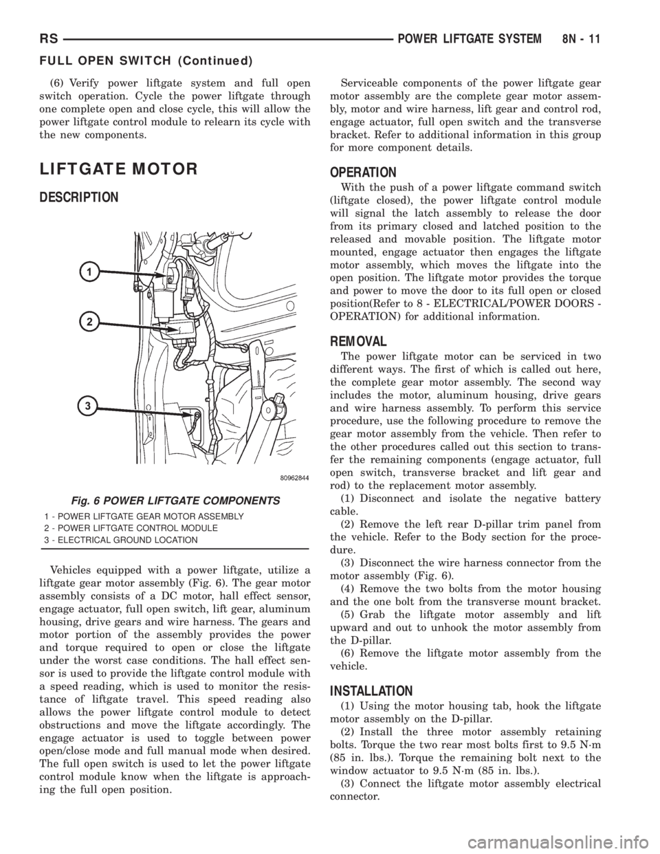
Vehicles equipped with a power liftgate, utilize a
liftgate gear motor assembly (Fig. 6). The gear motor
assembly consists of a DC motor, hall effect sensor,
engage actuator, full open switch, lift gear, aluminum
housing, drive gears and wire harness. The gears and
motor portion of the assembly provides the power
and torque required to open or close the liftgate
under the worst case conditions. The hall effect sen-
sor is used to provide the liftgate control module with
a speed reading, which is used to monitor the resis-
tance of liftgate travel. This speed reading also
allows the power liftgate control module to detect
obstructions and move the liftgate accordingly. The
engage actuator is used to toggle between power
open/close mode and full manual mode when desired.
The full open switch is used to let the power liftgate
control module know when the liftgate is approach-
ing the full open position.Serviceable components of the power liftgate gear
motor assembly are the complete gear motor assem-
bly, motor and wire harness, lift gear and control rod,
engage actuator, full open switch and the transverse
bracket. Refer to additional information in this group
for more component details.
OPERATION
With the push of a power liftgate command switch
(liftgate closed), the power liftgate control module
will signal the latch assembly to release the door
from its primary closed and latched position to the
released and movable position. The liftgate motor
mounted, engage actuator then engages the liftgate
motor assembly, which moves the liftgate into the
open position. The liftgate motor provides the torque
and power to move the door to its full open or closed
position(Refer to 8 - ELECTRICAL/POWER DOORS -
OPERATION) for additional information.
REMOVAL
The power liftgate motor can be serviced in two
different ways. The first of which is called out here,
the complete gear motor assembly. The second way
includes the motor, aluminum housing, drive gears
and wire harness assembly. To perform this service
procedure, use the following procedure to remove the
gear motor assembly from the vehicle. Then refer to
the other procedures called out this section to trans-
fer the remaining components (engage actuator, full
open switch, transverse bracket and lift gear and
rod) to the replacement motor assembly.
(1) Disconnect and isolate the negative battery
cable.
(2) Remove the left rear D-pillar trim panel from
the vehicle. Refer to the Body section for the proce-
dure.
(3) Disconnect the wire harness connector from the
motor assembly (Fig. 6).
(4) Remove the two bolts from the motor housing
and the one bolt from the transverse mount bracket.
(5) Grab the liftgate motor assembly and lift
upward and out to unhook the motor assembly from
the D-pillar.
(6) Remove the liftgate motor assembly from the
vehicle.
INSTALLATION
(1) Using the motor housing tab, hook the liftgate
motor assembly on the D-pillar.
(2) Install the three motor assembly retaining
bolts. Torque the two rear most bolts first to 9.5 N´m
(85 in. lbs.). Torque the remaining bolt next to the
window actuator to 9.5 N´m (85 in. lbs.).
(3) Connect the liftgate motor assembly electrical
connector.
Fig. 6 POWER LIFTGATE COMPONENTS
1 - POWER LIFTGATE GEAR MOTOR ASSEMBLY
2 - POWER LIFTGATE CONTROL MODULE
3 - ELECTRICAL GROUND LOCATION
RSPOWER LIFTGATE SYSTEM8N-11
FULL OPEN SWITCH (Continued)
Page 1995 of 4284
LATCH
DESCRIPTION
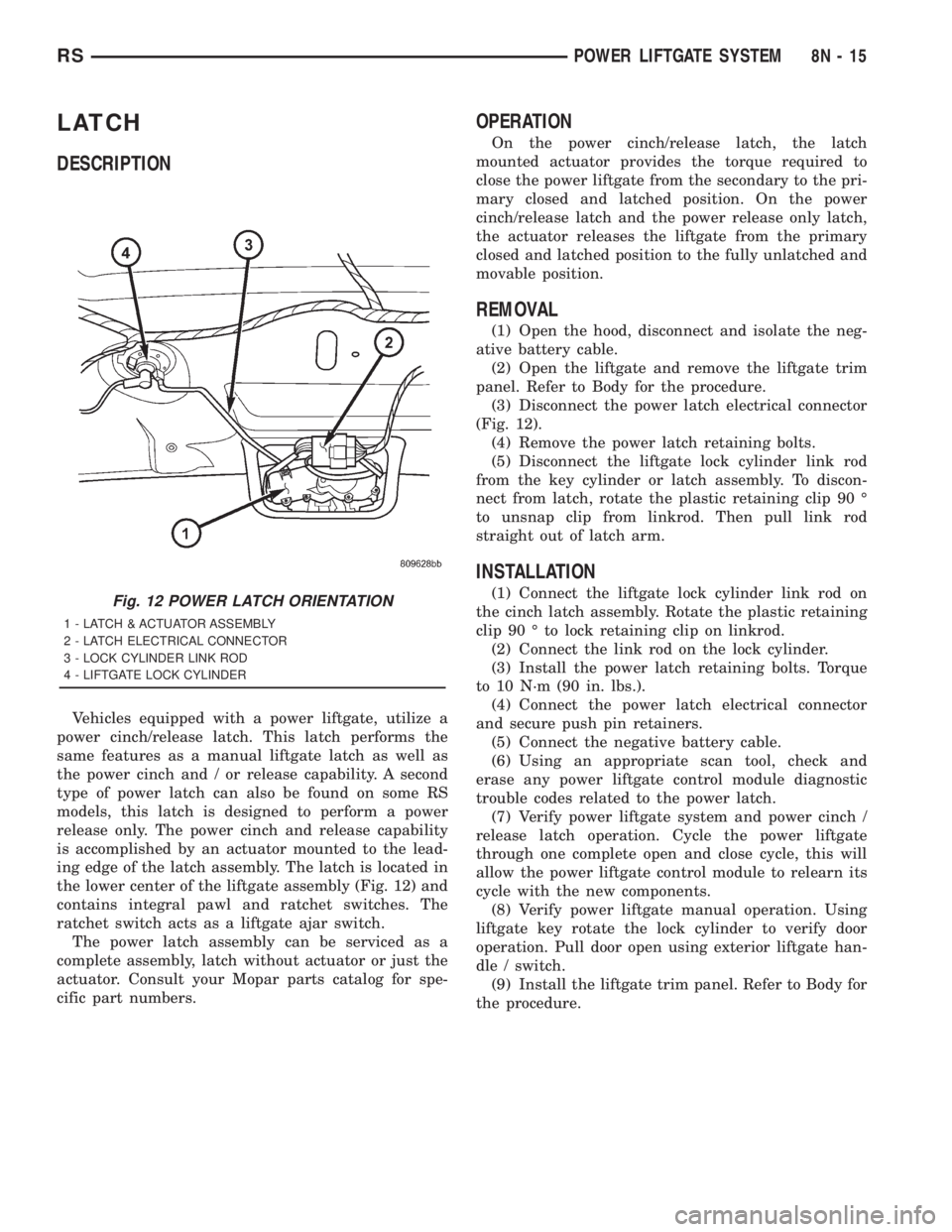
Vehicles equipped with a power liftgate, utilize a
power cinch/release latch. This latch performs the
same features as a manual liftgate latch as well as
the power cinch and / or release capability. A second
type of power latch can also be found on some RS
models, this latch is designed to perform a power
release only. The power cinch and release capability
is accomplished by an actuator mounted to the lead-
ing edge of the latch assembly. The latch is located in
the lower center of the liftgate assembly (Fig. 12) and
contains integral pawl and ratchet switches. The
ratchet switch acts as a liftgate ajar switch.
The power latch assembly can be serviced as a
complete assembly, latch without actuator or just the
actuator. Consult your Mopar parts catalog for spe-
cific part numbers.
OPERATION
On the power cinch/release latch, the latch
mounted actuator provides the torque required to
close the power liftgate from the secondary to the pri-
mary closed and latched position. On the power
cinch/release latch and the power release only latch,
the actuator releases the liftgate from the primary
closed and latched position to the fully unlatched and
movable position.
REMOVAL
(1) Open the hood, disconnect and isolate the neg-
ative battery cable.
(2) Open the liftgate and remove the liftgate trim
panel. Refer to Body for the procedure.
(3) Disconnect the power latch electrical connector
(Fig. 12).
(4) Remove the power latch retaining bolts.
(5) Disconnect the liftgate lock cylinder link rod
from the key cylinder or latch assembly. To discon-
nect from latch, rotate the plastic retaining clip 90 É
to unsnap clip from linkrod. Then pull link rod
straight out of latch arm.
INSTALLATION
(1) Connect the liftgate lock cylinder link rod on
the cinch latch assembly. Rotate the plastic retaining
clip 90 É to lock retaining clip on linkrod.
(2) Connect the link rod on the lock cylinder.
(3) Install the power latch retaining bolts. Torque
to 10 N´m (90 in. lbs.).
(4) Connect the power latch electrical connector
and secure push pin retainers.
(5) Connect the negative battery cable.
(6) Using an appropriate scan tool, check and
erase any power liftgate control module diagnostic
trouble codes related to the power latch.
(7) Verify power liftgate system and power cinch /
release latch operation. Cycle the power liftgate
through one complete open and close cycle, this will
allow the power liftgate control module to relearn its
cycle with the new components.
(8) Verify power liftgate manual operation. Using
liftgate key rotate the lock cylinder to verify door
operation. Pull door open using exterior liftgate han-
dle / switch.
(9) Install the liftgate trim panel. Refer to Body for
the procedure.Fig. 12 POWER LATCH ORIENTATION
1 - LATCH & ACTUATOR ASSEMBLY
2 - LATCH ELECTRICAL CONNECTOR
3 - LOCK CYLINDER LINK ROD
4 - LIFTGATE LOCK CYLINDER
RSPOWER LIFTGATE SYSTEM8N-15
Page 2007 of 4284
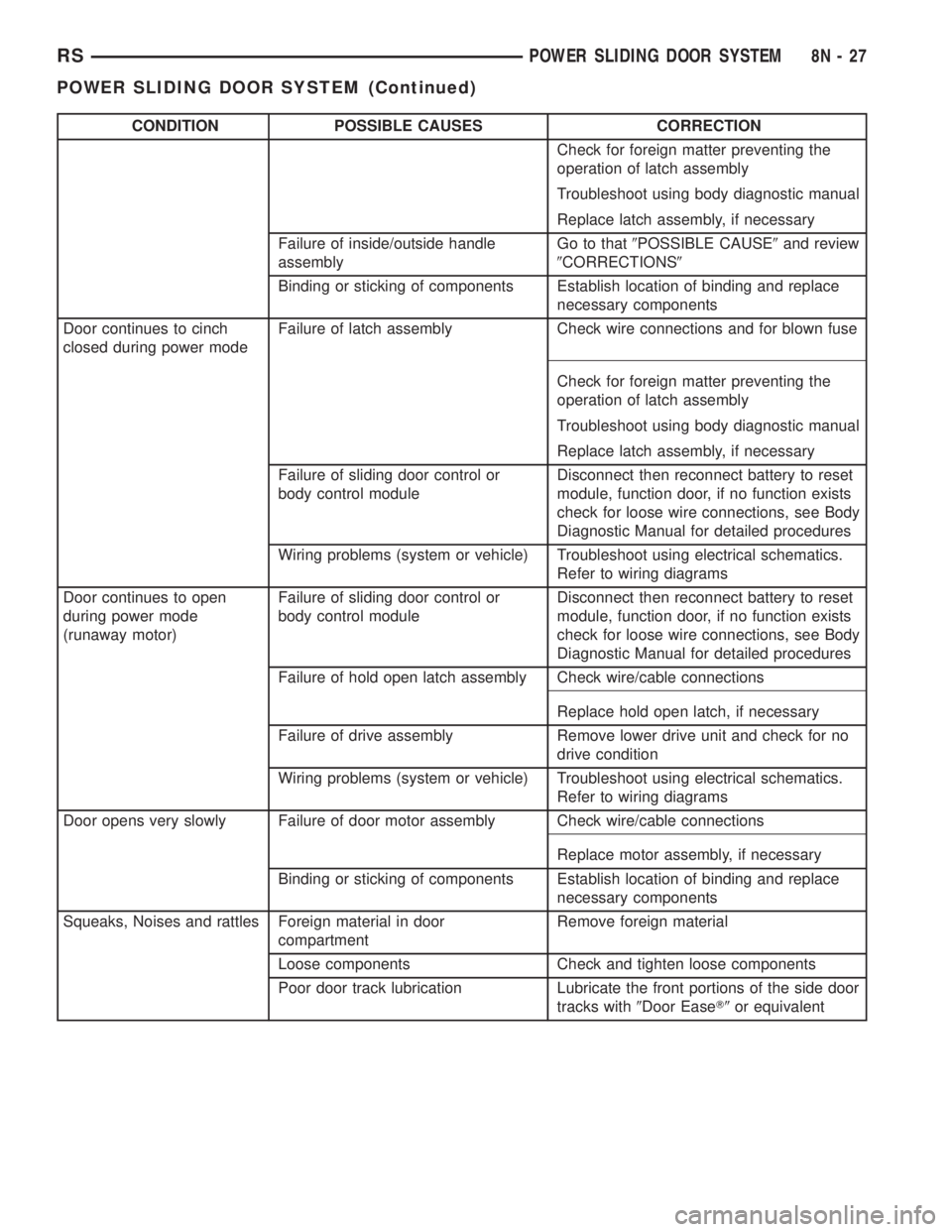
CONDITION POSSIBLE CAUSES CORRECTION
Check for foreign matter preventing the
operation of latch assembly
Troubleshoot using body diagnostic manual
Replace latch assembly, if necessary
Failure of inside/outside handle
assemblyGo to that9POSSIBLE CAUSE9and review
9CORRECTIONS9
Binding or sticking of components Establish location of binding and replace
necessary components
Door continues to cinch
closed during power modeFailure of latch assembly Check wire connections and for blown fuse
Check for foreign matter preventing the
operation of latch assembly
Troubleshoot using body diagnostic manual
Replace latch assembly, if necessary
Failure of sliding door control or
body control moduleDisconnect then reconnect battery to reset
module, function door, if no function exists
check for loose wire connections, see Body
Diagnostic Manual for detailed procedures
Wiring problems (system or vehicle) Troubleshoot using electrical schematics.
Refer to wiring diagrams
Door continues to open
during power mode
(runaway motor)Failure of sliding door control or
body control moduleDisconnect then reconnect battery to reset
module, function door, if no function exists
check for loose wire connections, see Body
Diagnostic Manual for detailed procedures
Failure of hold open latch assembly Check wire/cable connections
Replace hold open latch, if necessary
Failure of drive assembly Remove lower drive unit and check for no
drive condition
Wiring problems (system or vehicle) Troubleshoot using electrical schematics.
Refer to wiring diagrams
Door opens very slowly Failure of door motor assembly Check wire/cable connections
Replace motor assembly, if necessary
Binding or sticking of components Establish location of binding and replace
necessary components
Squeaks, Noises and rattles Foreign material in door
compartmentRemove foreign material
Loose components Check and tighten loose components
Poor door track lubrication Lubricate the front portions of the side door
tracks with9Door EaseT9or equivalent
RSPOWER SLIDING DOOR SYSTEM8N-27
POWER SLIDING DOOR SYSTEM (Continued)
Page 2020 of 4284
REMOTE KEYLESS ENTRY SYSTEM
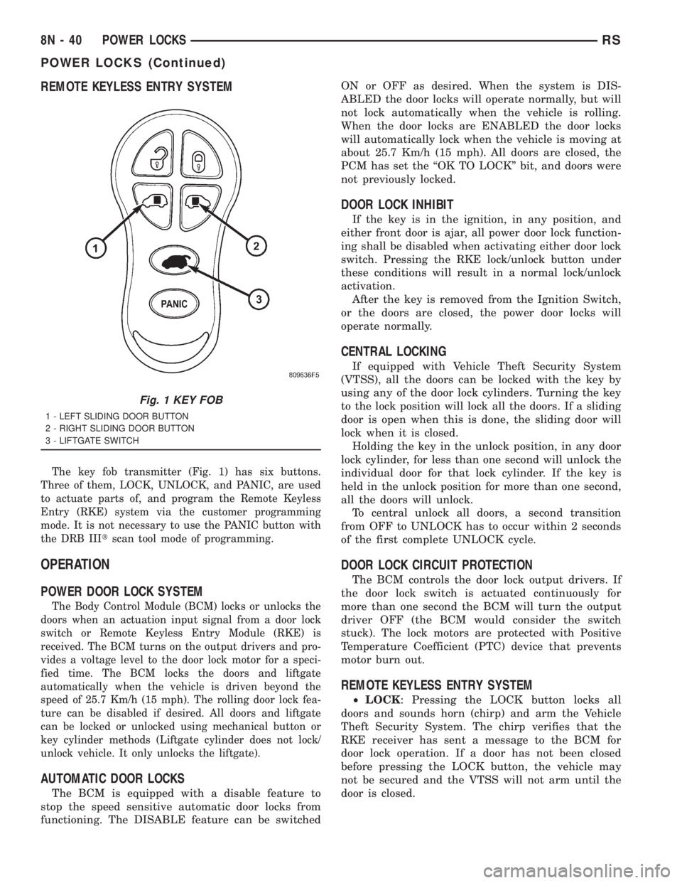
The key fob transmitter (Fig. 1) has six buttons.
Three of them, LOCK, UNLOCK, and PANIC, are used
to actuate parts of, and program the Remote Keyless
Entry (RKE) system via the customer programming
mode. It is not necessary to use the PANIC button with
the DRB IIItscan tool mode of programming.
OPERATION
POWER DOOR LOCK SYSTEM
The Body Control Module (BCM) locks or unlocks the
doors when an actuation input signal from a door lock
switch or Remote Keyless Entry Module (RKE) is
received. The BCM turns on the output drivers and pro-
vides a voltage level to the door lock motor for a speci-
fied time. The BCM locks the doors and liftgate
automatically when the vehicle is driven beyond the
speed of 25.7 Km/h (15 mph). The rolling door lock fea-
ture can be disabled if desired. All doors and liftgate
can be locked or unlocked using mechanical button or
key cylinder methods (Liftgate cylinder does not lock/
unlock vehicle. It only unlocks the liftgate).
AUTOMATIC DOOR LOCKS
The BCM is equipped with a disable feature to
stop the speed sensitive automatic door locks from
functioning. The DISABLE feature can be switchedON or OFF as desired. When the system is DIS-
ABLED the door locks will operate normally, but will
not lock automatically when the vehicle is rolling.
When the door locks are ENABLED the door locks
will automatically lock when the vehicle is moving at
about 25.7 Km/h (15 mph). All doors are closed, the
PCM has set the ªOK TO LOCKº bit, and doors were
not previously locked.
DOOR LOCK INHIBIT
If the key is in the ignition, in any position, and
either front door is ajar, all power door lock function-
ing shall be disabled when activating either door lock
switch. Pressing the RKE lock/unlock button under
these conditions will result in a normal lock/unlock
activation.
After the key is removed from the Ignition Switch,
or the doors are closed, the power door locks will
operate normally.
CENTRAL LOCKING
If equipped with Vehicle Theft Security System
(VTSS), all the doors can be locked with the key by
using any of the door lock cylinders. Turning the key
to the lock position will lock all the doors. If a sliding
door is open when this is done, the sliding door will
lock when it is closed.
Holding the key in the unlock position, in any door
lock cylinder, for less than one second will unlock the
individual door for that lock cylinder. If the key is
held in the unlock position for more than one second,
all the doors will unlock.
To central unlock all doors, a second transition
from OFF to UNLOCK has to occur within 2 seconds
of the first complete UNLOCK cycle.
DOOR LOCK CIRCUIT PROTECTION
The BCM controls the door lock output drivers. If
the door lock switch is actuated continuously for
more than one second the BCM will turn the output
driver OFF (the BCM would consider the switch
stuck). The lock motors are protected with Positive
Temperature Coefficient (PTC) device that prevents
motor burn out.
REMOTE KEYLESS ENTRY SYSTEM
²LOCK: Pressing the LOCK button locks all
doors and sounds horn (chirp) and arm the Vehicle
Theft Security System. The chirp verifies that the
RKE receiver has sent a message to the BCM for
door lock operation. If a door has not been closed
before pressing the LOCK button, the vehicle may
not be secured and the VTSS will not arm until the
door is closed.
Fig. 1 KEY FOB
1 - LEFT SLIDING DOOR BUTTON
2 - RIGHT SLIDING DOOR BUTTON
3 - LIFTGATE SWITCH
8N - 40 POWER LOCKSRS
POWER LOCKS (Continued)
Page 2021 of 4284
²UNLOCK: Pressing the UNLOCK button once
will unlock the driver's side doors and activate the
illuminated entry system and disarm Vehicle Theft
Security System, if equipped. Pressing the UNLOCK
button twice within five seconds will unlock all doors
and activate the illuminated entry system.
²LEFT SLIDING DOOR: Pressing the LEFT
SLIDING DOOR BUTTON opens/closes the left
power sliding door remotely.
²RIGHT SLIDING DOOR: Pressing the RIGHT
SLIDING DOOR BUTTON opens/closes the right
power sliding door remotely.
²LIFTGATE: Pressing the LIFTGATE BUTTON
opens/closes the liftgate remotely.
²PANIC: Pressing the PANIC button sounds the
horns at half second intervals, flashes the exterior
lamps, and turns ON the interior lamps. The panic
alarm will remain on for three minutes, or until the
PANIC button is actuated again or the ignition
switch is turned to the RUN position.
The Remote Keyless Entry Module is capable of
retaining the transmitter Vehicle Access Code(s)
(VAC) in its memory even after vehicle power has
been interrupted.
NOTE: Additional features available to the customer
are described in the Vehicle Owners Manual.
The RKE system activates the optional memory
seat and mirror system, if equipped. Two primary
key fob transmitters can be programmed to actuate
memory seat and mirror setting 1 or 2. Two addi-
tional key fob transmitters can be added, but they
will not be able to operate the memory seat and mir-
ror system (Refer to 8 - ELECTRICAL/POWER
SEATS - OPERATION) and (Refer to 8 - ELECTRI-
CAL/POWER MIRRORS - OPERATION).
DOOR LOCK MOTOR
DIAGNOSIS AND TESTING - DOOR LOCK
MOTOR
Verify battery condition before testing door lock
motor(s) (Refer to 8 - ELECTRICAL/BATTERY SYS-
TEM/BATTERY - DIAGNOSIS AND TESTING).
To determine which motor is faulty, check each
individual door for electrical lock and unlock or dis-
connect the motor connectors one at a time, while
operating the door lock switch. In the event that
none of the motors work, the problem may be caused
by a shorted motor or a bad switch. Disconnecting
the defective motor will allow the others to work.
To test an individual door lock motor, disconnect
the electrical connector from the motor. To lock the
door, connect a 12 volt power source to the positivepin of the lock motor and a ground wire to the other
pin. Refer to the appropriate wiring information. The
wiring information includes wiring diagrams, proper
wire and connector repair procedures, further details
on wire harness routing and retention, as well as
pin-out and location views for the various wire har-
ness connectors, splices and grounds. To unlock the
door reverse the wire connections at the motor pin
terminals. If these results are NOT obtained, replace
the motor.
DOOR LOCK SWITCH
DESCRIPTION
The Power Door Lock Switch is attached to the
door trim panel with two screws.
DIAGNOSIS AND TESTING - DOOR LOCK
SWITCH
(1) Remove door trim panel. Refer to Body, Door -
Front, Trim Panel, Removal and Installation.
(2) Disconnect wire connector from back of door
lock switch.
(3) Depress switch to LOCK position.
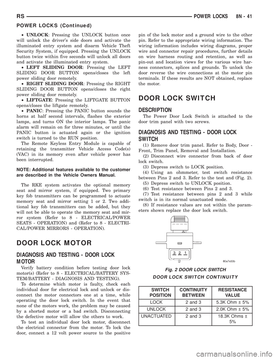
(4) Using an ohmmeter, test switch resistance
between Pins 2 and 3. Refer to the test and (Fig. 2).
(5) Depress switch to UNLOCK position.
(6) Test resistance between Pins 2 and 3.
(7) Test resistance between pins 2 and 3 while
switch is in its normal unactuated mode.
(8) If resistance values are not within the param-
eters shown replace the door lock switch.
DOOR LOCK SWITCH CONTINUITY
SWITCH
POSITIONCONTINUITY
BETWEENRESISTANCE
VALUE
LOCK 2 and 3 5.3K Ohm 5%
UNLOCK 2 and 3 2.0K Ohm 5%
UNACTUATED 2 and 3 18.3K Ohms
5%
Fig. 2 DOOR LOCK SWITCH
RSPOWER LOCKS8N-41
POWER LOCKS (Continued)
Page 2023 of 4284
REMOTE KEYLESS ENTRY
MODULE
DESCRIPTION
The RKE module is capable of retaining up to four
different Vehicle Access Codes.
OPERATION
Whenever the vehicle battery power is interrupted
the RKE Module will retain all vehicle access codes
in its memory. When replacing or adding a key fob
transmitter (maximum 4) a DRB IIItscan tool is
required to program the RKE Module to accept the
new Vehicle Access Code if a customer owned trans-
mitter is not available. Refer to Electrical, Remote
Keyless Entry Module, Standard Procedure - Pro-
gramming RKE Module or the Proper Body Diagnos-
tic Procedures manual.
DIAGNOSIS AND TESTING - REMOTE KEYLESS
ENTRY
Refer to the appropriate wiring information. The
wiring information includes wiring diagrams, proper
wire and connector repair procedures, further details
on wire harness routing and retention, as well as
pin-out and location views for the various wire har-
ness connectors, splices and grounds. Refer to the
proper Body Diagnostic Procedures Manual for test-
ing the Remote Keyless Entry system using a DRB
IIItscan tool. Also refer to other interrelated sys-
tems groups within this manual:
²Vehicle Theft Security System
²Power Seats
²Power Mirrors
STANDARD PROCEDURE - PROGRAMMING
RKE MODULE
(1) Using a functional key fob transmitter, unlock
the vehicle and disarm the Vehicle Theft Security
System.
(2) Insert ignition key into the ignition switch.
(3) Turn the ignition switch to RUN position with-
out starting engine.
(4) Using a functional key fob transmitter, press
and hold the UNLOCK button for a minimum five
seconds (maximum ten seconds).
(5) While still holding UNLOCK button, and
before ten seconds passes, press the PANIC button
and release both at the same time. A single chime
will sound to verify that the RKE module is set to
receive the new Vehicle Access Code(s).
(6) Within 30 seconds of the chime, press and
release the ªLOCKº and ªUNLOCKº buttons on the
transmitter at the same time. Then press any one of
the buttons. The BCM will sound an abbreviatedchime to acknowledge that the programming of the
transmitter has been completed and was successful.
(7) Repeat step 6 for all transmitters that will be
used with this vehicle (up to 4 total).
(8) Programming mode will last for 30 seconds. To
get out of programming mode sooner, turn the igni-
tion OFF. A single chime will sound to verify that the
RKE module will no longer accept additional Vehicle
Access Code(s).
(9) When Vehicle Access Code(s) programming is
complete, turn the ignition switch to the OFF posi-
tion and verify RKE system operation using each key
fob.
NOTE:
Only the two key fob transmitters that have been
programmed to the memory seat and mirror system
will operate it. If any key fob is replaced, the mem-
ory seat and mirror module will require program-
ming. (Refer to 8 - ELECTRICAL/POWER SEATS -
DIAGNOSIS AND TESTING).
REMOVAL
(1) Disconnect and isolate the battery negative
cable.
(2) Remove instrument panel top cover (Refer to
23 - BODY/INSTRUMENT PANEL/INSTRUMENT
PANEL TOP PAD - REMOVAL).
(3) Remove screws holding RKE module to instru-
ment panel.
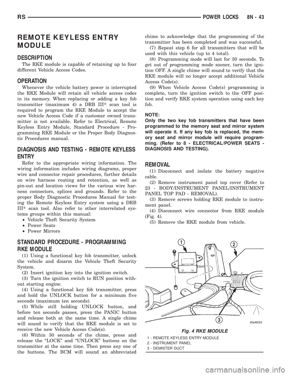
(4) Disconnect wire connector from RKE module
(Fig. 4).
(5) Remove the RKE module from vehicle.
Fig. 4 RKE MODULE
1 - REMOTE KEYLESS ENTRY MODULE
2 - INSTRUMENT PANEL
3 - DEMISTER DUCT
RSPOWER LOCKS8N-43