engine CHRYSLER VOYAGER 2001 Service Manual
[x] Cancel search | Manufacturer: CHRYSLER, Model Year: 2001, Model line: VOYAGER, Model: CHRYSLER VOYAGER 2001Pages: 4284, PDF Size: 83.53 MB
Page 3068 of 4284
pressure. Generally governor pressure ranges from
0-100 psi from idle to maximum speed, and rises pro-
portionally with the increase in output shaft speed.
Governor pressure and throttle pressure are acting
upon the shift valves to determine when a shift will
occur. Governor pressure is a direct indication of road
speed, and throttle pressure is an indication of
engine load. When both parameters have been met
by the throttle and governor pressures, an upshift or
downshift will occur.
CLEANING
Thoroughly clean all the governor parts in a suit-
able cleaning solution but do not use any type of
caustic cleaning agents.
The governor weight components and the governor
valve, must slide freely in their bores when clean and
dry. Minor surface scratches and burrs can be
smoothed with crocus cloth.
INSPECTION
The aluminum governor valve and outer weight
have a hard coating on them. Check condition of this
coating carefully. Do not reuse either part if the coat-
ing is damaged.
Inspect the governor weight spring for distortion.
Replace the spring, if distorted, collapsed, or broken.
Clean the filter in solvent and dry it with compressedair. Replace the filter, if damaged. Inspect the park
gear for chipped or worn gear teeth or damaged ring
grooves. Replace the gear, if damaged.
Check the teeth on the park gear for wear or dam-
age. Replace the gear if necessary. Inspect the metal
seal rings on the park gear hub. Replace the rings
only if severely worn, or broken.
OIL PUMP
DESCRIPTION
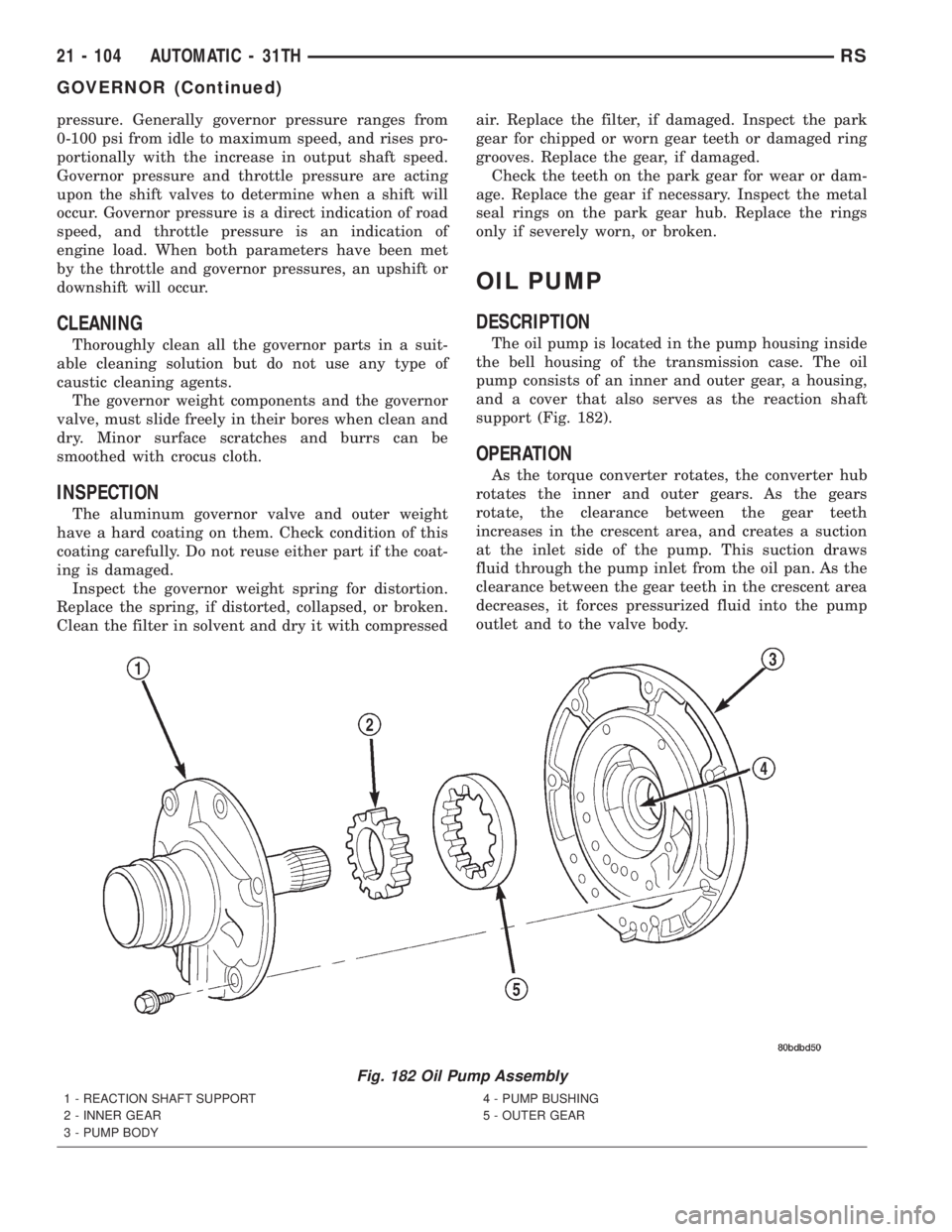
The oil pump is located in the pump housing inside
the bell housing of the transmission case. The oil
pump consists of an inner and outer gear, a housing,
and a cover that also serves as the reaction shaft
support (Fig. 182).
OPERATION
As the torque converter rotates, the converter hub
rotates the inner and outer gears. As the gears
rotate, the clearance between the gear teeth
increases in the crescent area, and creates a suction
at the inlet side of the pump. This suction draws
fluid through the pump inlet from the oil pan. As the
clearance between the gear teeth in the crescent area
decreases, it forces pressurized fluid into the pump
outlet and to the valve body.
Fig. 182 Oil Pump Assembly
1 - REACTION SHAFT SUPPORT
2 - INNER GEAR
3 - PUMP BODY4 - PUMP BUSHING
5 - OUTER GEAR
21 - 104 AUTOMATIC - 31THRS
GOVERNOR (Continued)
Page 3069 of 4284
STANDARD PROCEDURE - OIL PUMP VOLUME
CHECK
Measuring the oil pump output volume will deter-
mine if sufficient oil flow to the transmission oil
cooler exists, and whether or not an internal trans-
mission failure is present.
Verify that the transmission fluid is at the proper
level. Refer to the Fluid Level Check procedure in
this section. If necessary, fill the transmission to the
proper level with Moparž ATF +4, type 9602, Auto-
matic Transmission Fluid.
(1) Using hose cutters or a suitable blade, cut the
To coolerline off flush with the cooler inlet fitting
and place a collecting container under the open line.
CAUTION: With the fluid set at the proper level,
fluid collection should not exceed (1) quart or inter-
nal damage to the transmission may occur.
(2) Run the engineat curb idle speed, with the
shift selector in neutral.
(3) If one quart of transmission fluid is collected in
the container in 20 seconds or less, oil pump flow vol-
ume is within acceptable limits. If fluid flow is inter-
mittent, or it takes more than 20 seconds to collect
one quart of fluid, (Refer to 21 - TRANSMISSION/
TRANSAXLE/AUTOMATIC - 31TH - DIAGNOSIS
AND TESTING) for further diagnosis.
(4) Re-connect theTo coolerline to the transmis-
sion cooler inlet using a service splice kit. Refer to
instructions included with the kit.
(5) Refill the transmission to proper level. (Refer
to 21 - TRANSMISSION/TRANSAXLE/AUTOMATIC
- 31TH/FLUID - STANDARD PROCEDURE)
DISASSEMBLY
(1) Remove reaction shaft support-to-pump body
bolts.
(2) Remove reaction shaft support, and the inner
and outer pump gears (Fig. 183).
CLEANING
Clean pump and support components with solvent
and dry them with compressed air.
INSPECTION
(1) Check condition of the seal rings and thrust
washer on the reaction shaft support. The seal rings
do not need to be replaced unless cracked, broken, or
severely worn.
(2) Visually inspect the pump and support compo-
nents. Replace the pump assembly if the seal ring
grooves or machined surfaces are worn, scored, pit-
ted, or damaged. Replace the pump assembly if the
gears if pitted, worn chipped, or damaged.
(3) Inspect the pump bushing. Then check the
reaction shaft support bushing. Replace the pump
assembly if either bushing is heavily worn, scored or
damaged.
(4) Clearance between outer gear and reaction
shaft housing should be 0.010 to 0.063 mm (0.0004 to
0.0025 in.). Clearance between inner gear and reac-
tion shaft housing should be 0.010 to 0.063 mm
(0.0004 to 0.0025 in.). Both clearances can be mea-
sured at the same time by installing the gears in the
pump body and measure pump component clearances
as follows:
(5) Reinstall gears to pump body and measure
outer gear-to-pocket clearance with a feeler gauge
(Fig. 184).Outer gear-to-pocket clearance should
be within 0.045-0.141 mm (0.0018-0.0056 in.).
(6) Measure both inner and outer gear side clear-
ance with PlastigageŸ. If PlastigageŸ is not avail-
able, measure across the pump body with a straight
edge and feeler gauge.
(a) Position an appropriate piece of PlastigageŸ
across both gears.
(b) Align the plastigage to a flat area on the
reaction shaft housing.
(c) Install the reaction shaft support to the
pump housing and torque to 28 N´m (250 in. lbs.).
(d) Separate the reaction shaft housing from the
pump housing and measure the PlastigageŸ fol-
lowing the instructions supplied with it.Inner
and outer gear side clearance should be
within 0.020-0.046 mm (0.0008-0.0018 in.).
ASSEMBLY
(1) Install inner and outer gears to pump body
(Fig. 183). Lubricate gears with Moparž ATF+4
(Automatic Transmission Fluid-Type 9602).
(2) Install reaction shaft support to pump body
and align holes.
(3) Install and torque reaction shaft support-to-
pump body bolts to 28 N´m (250 in. lbs.).
RSAUTOMATIC - 31TH21 - 105
OIL PUMP (Continued)
Page 3073 of 4284
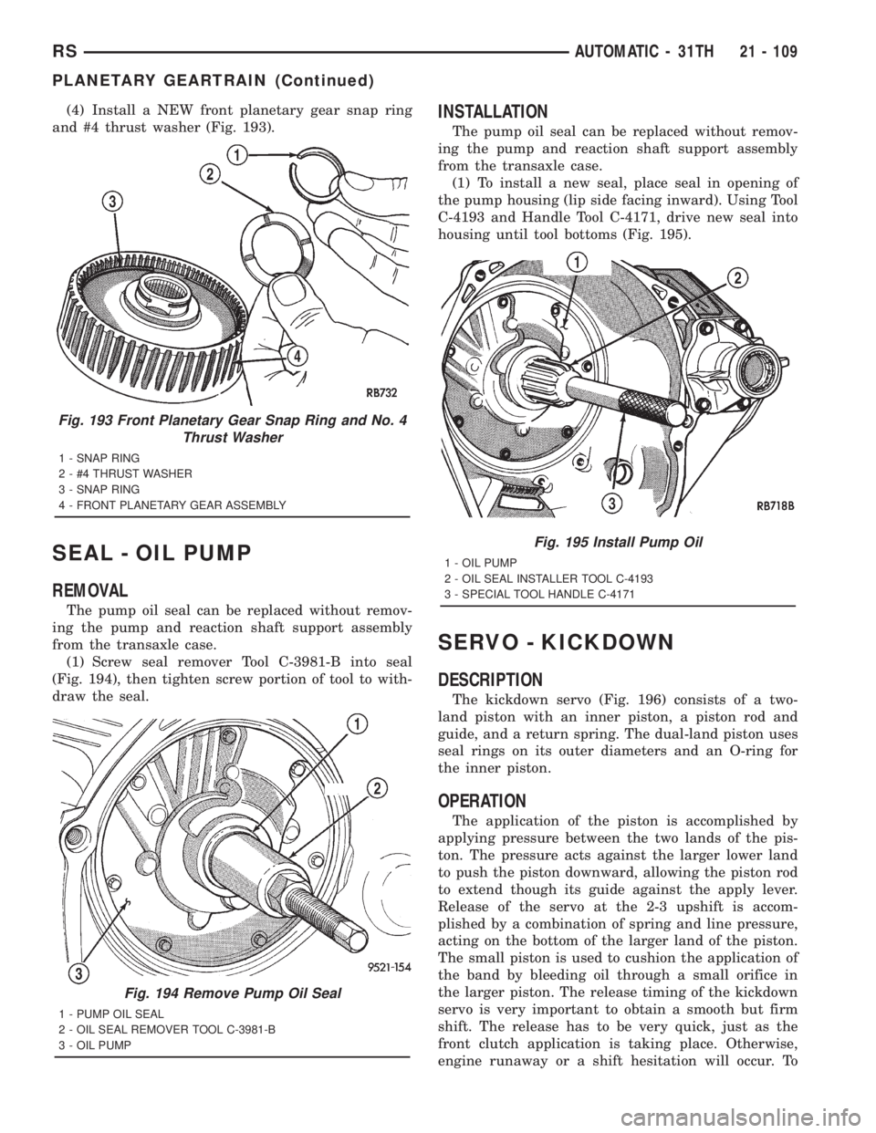
(4) Install a NEW front planetary gear snap ring
and #4 thrust washer (Fig. 193).
SEAL - OIL PUMP
REMOVAL
The pump oil seal can be replaced without remov-
ing the pump and reaction shaft support assembly
from the transaxle case.
(1) Screw seal remover Tool C-3981-B into seal
(Fig. 194), then tighten screw portion of tool to with-
draw the seal.
INSTALLATION
The pump oil seal can be replaced without remov-
ing the pump and reaction shaft support assembly
from the transaxle case.
(1) To install a new seal, place seal in opening of
the pump housing (lip side facing inward). Using Tool
C-4193 and Handle Tool C-4171, drive new seal into
housing until tool bottoms (Fig. 195).
SERVO - KICKDOWN
DESCRIPTION
The kickdown servo (Fig. 196) consists of a two-
land piston with an inner piston, a piston rod and
guide, and a return spring. The dual-land piston uses
seal rings on its outer diameters and an O-ring for
the inner piston.
OPERATION
The application of the piston is accomplished by
applying pressure between the two lands of the pis-
ton. The pressure acts against the larger lower land
to push the piston downward, allowing the piston rod
to extend though its guide against the apply lever.
Release of the servo at the 2-3 upshift is accom-
plished by a combination of spring and line pressure,
acting on the bottom of the larger land of the piston.
The small piston is used to cushion the application of
the band by bleeding oil through a small orifice in
the larger piston. The release timing of the kickdown
servo is very important to obtain a smooth but firm
shift. The release has to be very quick, just as the
front clutch application is taking place. Otherwise,
engine runaway or a shift hesitation will occur. To
Fig. 193 Front Planetary Gear Snap Ring and No. 4
Thrust Washer
1 - SNAP RING
2 - #4 THRUST WASHER
3 - SNAP RING
4 - FRONT PLANETARY GEAR ASSEMBLY
Fig. 194 Remove Pump Oil Seal
1 - PUMP OIL SEAL
2 - OIL SEAL REMOVER TOOL C-3981-B
3 - OIL PUMP
Fig. 195 Install Pump Oil
1 - OIL PUMP
2 - OIL SEAL INSTALLER TOOL C-4193
3 - SPECIAL TOOL HANDLE C-4171
RSAUTOMATIC - 31TH21 - 109
PLANETARY GEARTRAIN (Continued)
Page 3084 of 4284
THROTTLE VALVE LINKAGE ADJUSTMENT
The throttle valve linkage adjustment is very
important to proper transaxle operation. This adjust-
ment positions a valve which controls shift speed,
shift quality, and part throttle downshift sensitivity.
If the setting is too short, early shifts and slippage
between shifts may occur. If the setting is too long,
shifts may be delayed and part throttle downshifts
may be very sensitive.
LINKAGE ADJUSTMENT PROCEDURE
(1) Perform transaxle throttle valve linkage
adjustment while engine is at normal operating tem-
perature.
(2) Using small screwdriver, disengage adjustment
lock at transaxle.
(3) Rotate lever at transaxle all the way to the left
side of vehicle against stop.
(4) Slide cable adjuster until cable core end
touches clip at throttle valve lever.
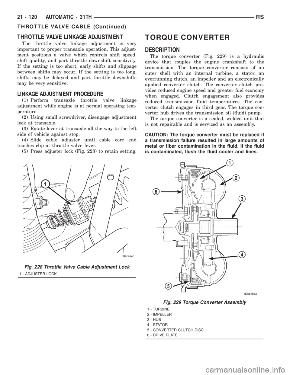
(5) Press adjuster lock (Fig. 228) to retain setting.
TORQUE CONVERTER
DESCRIPTION
The torque converter (Fig. 229) is a hydraulic
device that couples the engine crankshaft to the
transmission. The torque converter consists of an
outer shell with an internal turbine, a stator, an
overrunning clutch, an impeller and an electronically
applied converter clutch. The converter clutch pro-
vides reduced engine speed and greater fuel economy
when engaged. Clutch engagement also provides
reduced transmission fluid temperatures. The con-
verter clutch engages in third gear. The torque con-
verter hub drives the transmission oil (fluid) pump.
The torque converter is a sealed, welded unit that
is not repairable and is serviced as an assembly.
CAUTION: The torque converter must be replaced if
a transmission failure resulted in large amounts of
metal or fiber contamination in the fluid. If the fluid
is contaminated, flush the fluid cooler and lines.
Fig. 228 Throttle Valve Cable Adjustment Lock
1 - ADJUSTER LOCK
Fig. 229 Torque Converter Assembly
1 - TURBINE
2 - IMPELLER
3 - HUB
4-STATOR
5 - CONVERTER CLUTCH DISC
6 - DRIVE PLATE
21 - 120 AUTOMATIC - 31THRS
THROTTLE VALVE CABLE (Continued)
Page 3085 of 4284
IMPELLER
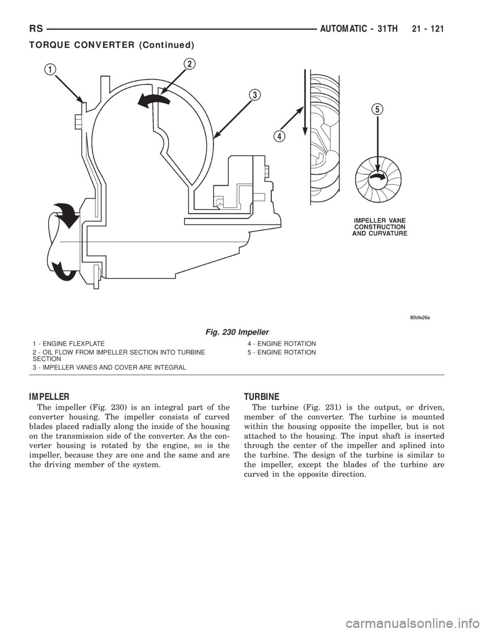
The impeller (Fig. 230) is an integral part of the
converter housing. The impeller consists of curved
blades placed radially along the inside of the housing
on the transmission side of the converter. As the con-
verter housing is rotated by the engine, so is the
impeller, because they are one and the same and are
the driving member of the system.
TURBINE
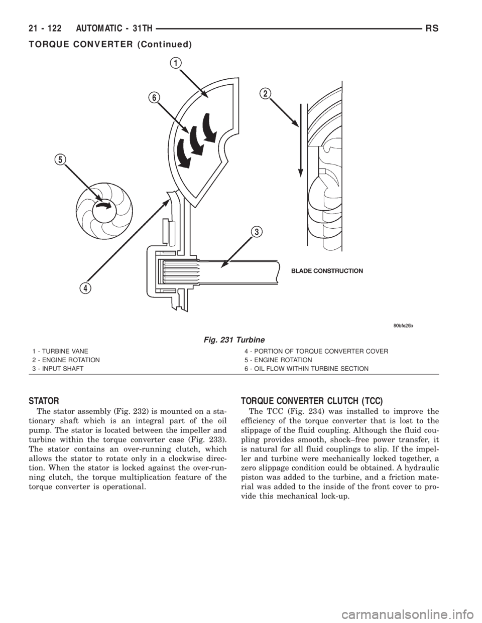
The turbine (Fig. 231) is the output, or driven,
member of the converter. The turbine is mounted
within the housing opposite the impeller, but is not
attached to the housing. The input shaft is inserted
through the center of the impeller and splined into
the turbine. The design of the turbine is similar to
the impeller, except the blades of the turbine are
curved in the opposite direction.
Fig. 230 Impeller
1 - ENGINE FLEXPLATE
2 - OIL FLOW FROM IMPELLER SECTION INTO TURBINE
SECTION
3 - IMPELLER VANES AND COVER ARE INTEGRAL4 - ENGINE ROTATION
5 - ENGINE ROTATION
RSAUTOMATIC - 31TH21 - 121
TORQUE CONVERTER (Continued)
Page 3086 of 4284
STATOR
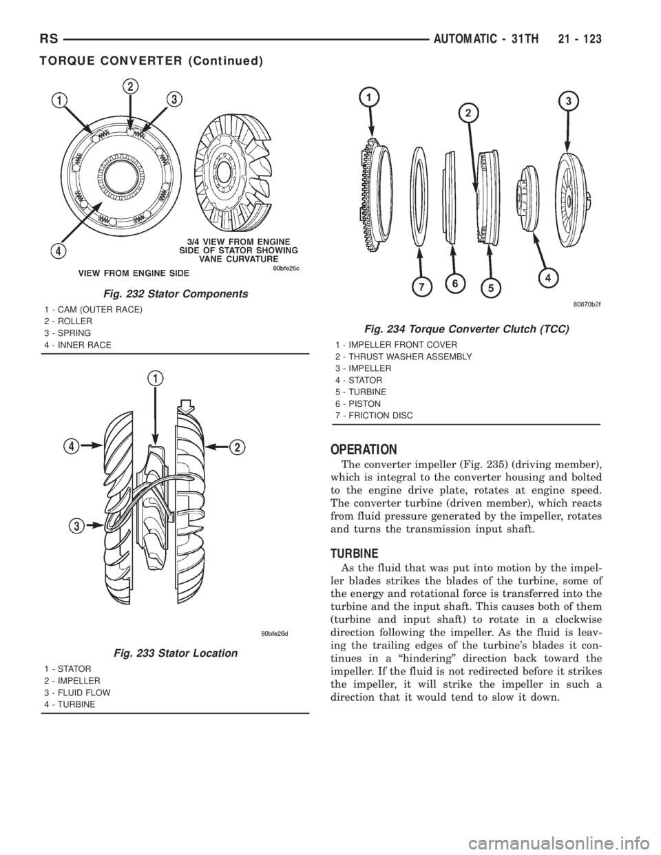
The stator assembly (Fig. 232) is mounted on a sta-
tionary shaft which is an integral part of the oil
pump. The stator is located between the impeller and
turbine within the torque converter case (Fig. 233).
The stator contains an over-running clutch, which
allows the stator to rotate only in a clockwise direc-
tion. When the stator is locked against the over-run-
ning clutch, the torque multiplication feature of the
torque converter is operational.
TORQUE CONVERTER CLUTCH (TCC)
The TCC (Fig. 234) was installed to improve the
efficiency of the torque converter that is lost to the
slippage of the fluid coupling. Although the fluid cou-
pling provides smooth, shock±free power transfer, it
is natural for all fluid couplings to slip. If the impel-
ler and turbine were mechanically locked together, a
zero slippage condition could be obtained. A hydraulic
piston was added to the turbine, and a friction mate-
rial was added to the inside of the front cover to pro-
vide this mechanical lock-up.
Fig. 231 Turbine
1 - TURBINE VANE
2 - ENGINE ROTATION
3 - INPUT SHAFT4 - PORTION OF TORQUE CONVERTER COVER
5 - ENGINE ROTATION
6 - OIL FLOW WITHIN TURBINE SECTION
21 - 122 AUTOMATIC - 31THRS
TORQUE CONVERTER (Continued)
Page 3087 of 4284
OPERATION
The converter impeller (Fig. 235) (driving member),
which is integral to the converter housing and bolted
to the engine drive plate, rotates at engine speed.
The converter turbine (driven member), which reacts
from fluid pressure generated by the impeller, rotates
and turns the transmission input shaft.
TURBINE
As the fluid that was put into motion by the impel-
ler blades strikes the blades of the turbine, some of
the energy and rotational force is transferred into the
turbine and the input shaft. This causes both of them
(turbine and input shaft) to rotate in a clockwise
direction following the impeller. As the fluid is leav-
ing the trailing edges of the turbine's blades it con-
tinues in a ªhinderingº direction back toward the
impeller. If the fluid is not redirected before it strikes
the impeller, it will strike the impeller in such a
direction that it would tend to slow it down.
Fig. 232 Stator Components
1 - CAM (OUTER RACE)
2 - ROLLER
3 - SPRING
4 - INNER RACE
Fig. 233 Stator Location
1-STATOR
2 - IMPELLER
3 - FLUID FLOW
4 - TURBINE
Fig. 234 Torque Converter Clutch (TCC)
1 - IMPELLER FRONT COVER
2 - THRUST WASHER ASSEMBLY
3 - IMPELLER
4-STATOR
5 - TURBINE
6 - PISTON
7 - FRICTION DISC
RSAUTOMATIC - 31TH21 - 123
TORQUE CONVERTER (Continued)
Page 3088 of 4284
STATOR
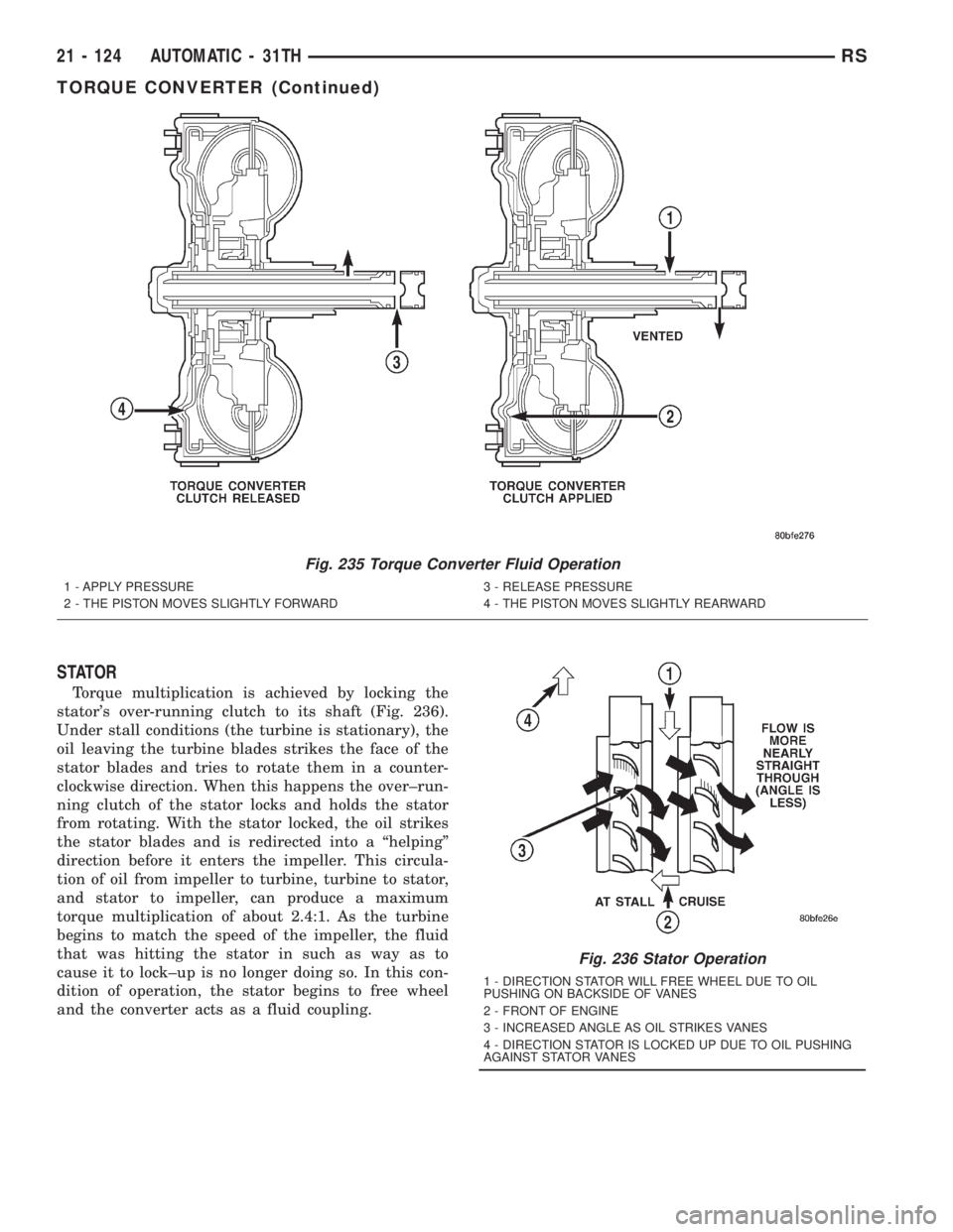
Torque multiplication is achieved by locking the
stator's over-running clutch to its shaft (Fig. 236).
Under stall conditions (the turbine is stationary), the
oil leaving the turbine blades strikes the face of the
stator blades and tries to rotate them in a counter-
clockwise direction. When this happens the over±run-
ning clutch of the stator locks and holds the stator
from rotating. With the stator locked, the oil strikes
the stator blades and is redirected into a ªhelpingº
direction before it enters the impeller. This circula-
tion of oil from impeller to turbine, turbine to stator,
and stator to impeller, can produce a maximum
torque multiplication of about 2.4:1. As the turbine
begins to match the speed of the impeller, the fluid
that was hitting the stator in such as way as to
cause it to lock±up is no longer doing so. In this con-
dition of operation, the stator begins to free wheel
and the converter acts as a fluid coupling.
Fig. 235 Torque Converter Fluid Operation
1 - APPLY PRESSURE
2 - THE PISTON MOVES SLIGHTLY FORWARD3 - RELEASE PRESSURE
4 - THE PISTON MOVES SLIGHTLY REARWARD
Fig. 236 Stator Operation
1 - DIRECTION STATOR WILL FREE WHEEL DUE TO OIL
PUSHING ON BACKSIDE OF VANES
2 - FRONT OF ENGINE
3 - INCREASED ANGLE AS OIL STRIKES VANES
4 - DIRECTION STATOR IS LOCKED UP DUE TO OIL PUSHING
AGAINST STATOR VANES
21 - 124 AUTOMATIC - 31THRS
TORQUE CONVERTER (Continued)
Page 3089 of 4284
TORQUE CONVERTER CLUTCH (TCC)
In a standard torque converter, the impeller and
turbine are rotating at about the same speed and the
stator is freewheeling, providing no torque multipli-
cation. By applying the turbine's piston to the front
cover's friction material, a total converter engage-
ment can be obtained. The result of this engagement
is a direct 1:1 mechanical link between the engine
and the transmission.
The engagement and disengagement of the TCC
are automatic and controlled by the Powertrain Con-
trol Module (PCM). The engagement cannot be acti-
vated in the lower gears because it eliminates the
torque multiplication effect of the torque converter
necessary for acceleration. Inputs that determine
clutch engagement are: coolant temperature, vehicle
speed and throttle position. The torque converter
clutch is engaged by the clutch solenoid on the valve
body. The clutch will engage at approximately 56
km/h (35 mph) with light throttle, after the shift to
third gear.
REMOVAL
(1) Remove transmission and torque converter
from vehicle. (Refer to 21 - TRANSMISSION/TRANS-
AXLE/AUTOMATIC - 31TH - REMOVAL)
(2) Place a suitable drain pan under the converter
housing end of the transmission.
CAUTION: Verify that transmission is secure on the
lifting device or work surface, the center of gravity
of the transmission will shift when the torque con-
verter is removed creating an unstable condition.
The torque converter is a heavy unit. Use caution
when separating the torque converter from the
transmission.
(3) Pull the torque converter forward until the cen-
ter hub clears the oil pump seal.
(4) Separate the torque converter from the trans-
mission.
INSTALLATION
Check converter hub and drive notches for sharp
edges, burrs, scratches, or nicks. Polish the hub and
notches with 320/400 grit paper or crocus cloth if nec-
essary. The hub must be smooth to avoid damaging
the pump seal at installation.(1) Lubricate converter hub and oil pump seal lip
with transmission fluid.
(2) Place torque converter in position on transmis-
sion.
CAUTION: Do not damage oil pump seal or bushing
while inserting torque converter into the front of the
transmission.
(3) Align torque converter to oil pump seal open-
ing.
(4) Insert torque converter hub into oil pump.
(5) While pushing torque converter inward, rotate
converter until converter is fully seated in the oil
pump gears.
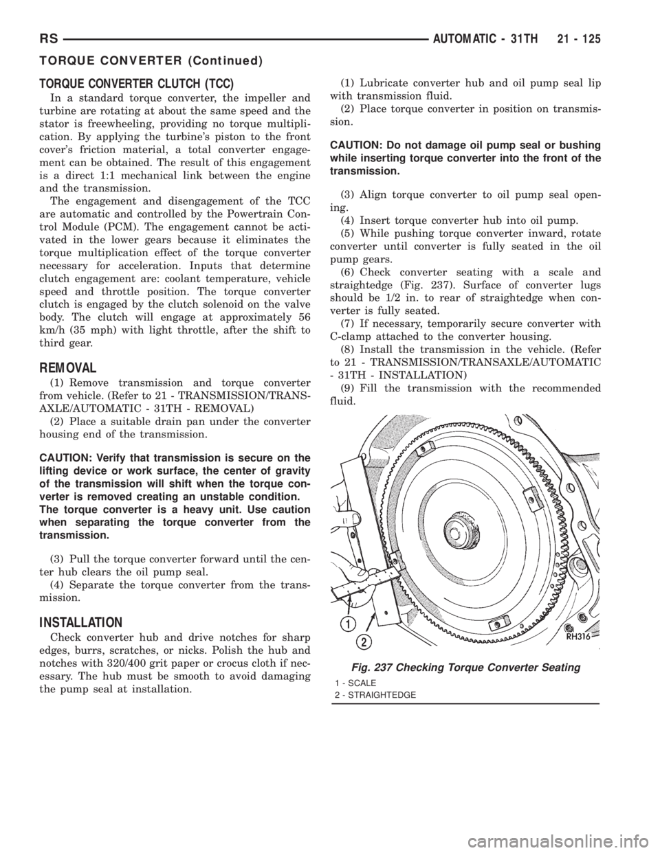
(6) Check converter seating with a scale and
straightedge (Fig. 237). Surface of converter lugs
should be 1/2 in. to rear of straightedge when con-
verter is fully seated.
(7) If necessary, temporarily secure converter with
C-clamp attached to the converter housing.
(8) Install the transmission in the vehicle. (Refer
to 21 - TRANSMISSION/TRANSAXLE/AUTOMATIC
- 31TH - INSTALLATION)
(9) Fill the transmission with the recommended
fluid.
Fig. 237 Checking Torque Converter Seating
1 - SCALE
2 - STRAIGHTEDGE
RSAUTOMATIC - 31TH21 - 125
TORQUE CONVERTER (Continued)
Page 3123 of 4284
VALVE BODY
DESCRIPTION..........................289
OPERATION............................290
REMOVAL.............................290DISASSEMBLY..........................292
ASSEMBLY............................296
INSTALLATION..........................301
AUTOMATIC - 41TE
TRANSAXLE IDENTIFICATION
DESCRIPTION
The 41TE (Fig. 1) is a four-speed transaxle that is
a conventional hydraulic/mechanical assembly with
an integral differential, and is controlled with adap-
tive electronic controls and monitors. The hydraulic
system of the transaxle consists of the transaxle
fluid, fluid passages, hydraulic valves, and various
line pressure control components. An input clutch
assembly which houses the underdrive, overdrive,
and reverse clutches is used. It also utilizes separate
holding clutches: 2nd/4th gear and Low/Reverse. The
primary mechanical components of the transaxle con-
sist of the following:
²Three multiple disc input clutches
²Two multiple disc holding clutches
²Four hydraulic accumulators
²Two planetary gear sets
²Hydraulic oil pump
²Valve body
²Solenoid/Pressure switch assembly
²Integral differential assembly
Control of the transaxle is accomplished by fully
adaptive electronics. Optimum shift scheduling is
accomplished through continuous real-time sensor
feedback information provided to the Transmission
Control Module (TCM).
The TCM is the heart of the electronic control sys-
tem and relies on information from various direct
and indirect inputs (sensors, switches, etc.) to deter-
mine driver demand and vehicle operating condi-
tions. With this information, the TCM can calculate
and perform timely and quality shifts through vari-
ous output or control devices (solenoid pack, trans-
mission control relay, etc.).
The TCM also performs certain self-diagnostic
functions and provides comprehensive information
(sensor data, DTC's, etc.) which is helpful in proper
diagnosis and repair. This information can be viewed
with the DRB scan tool.
The 41TE transaxle identification code is a series
of digits printed on a bar-code label that is fixed to
the transaxle case as shown in (Fig. 2).For example, the identification code K 821 1125
1316 can be broken down as follows:
²K = Kokomo Transmission Plant
²821 = Last three digits of the transaxle part
number
²1125 = Build date
²1316 = Build sequence number
If the tag is not legible or missing, the ªPKº num-
ber, which is stamped into the transaxle case behind
the transfer gear cover, can be referred to for identi-
fication. This number differs slightly in that it con-
tains the entire transaxle part number, rather than
the last three digits.
OPERATION
Transmission output is directed to an integral dif-
ferential by a transfer gear system in the following
input-to-output ratios:
First...............................2.84 : 1
Second.............................1.57 : 1
Third..............................1.00 : 1
Overdrive...........................0.69 : 1
Reverse............................2.21 : 1
DIAGNOSIS AND TESTING - 41TE TRANSAXLE
GENERAL DIAGNOSIS
NOTE: Before attempting any repair on a 41TE four-
speed automatic transaxle, check for diagnostic
trouble codes (DTC's) using the DRB scan tool.
Refer to the Transmission Diagnostic Procedures
Manual.
Transaxle malfunctions may be caused by these
general conditions:
²Poor engine performance
²Improper adjustments
²Hydraulic malfunctions
²Mechanical malfunctions
²Electronic malfunctions
Diagnosis of these problems should always begin
by checking the easily accessible variables: fluid level
and condition, gearshift cable adjustment. Then per-
form a road test to determine if the problem has been
corrected or that more diagnosis is necessary. If the
problem persists after the preliminary tests and cor-
rections are completed, hydraulic pressure checks
should be performed.
RSAUTOMATIC - 41TE21 - 159