diagram CHRYSLER VOYAGER 2001 Service Manual
[x] Cancel search | Manufacturer: CHRYSLER, Model Year: 2001, Model line: VOYAGER, Model: CHRYSLER VOYAGER 2001Pages: 4284, PDF Size: 83.53 MB
Page 27 of 4284
TABLE OF CONTENTS - Continued
RIGHT SLIDING DOOR CONTROL MODULE C1 (POWER SLIDING DOOR) - BLACK
8 WAY ..............................................................1082
RIGHT SLIDING DOOR CONTROL MODULE C2 (POWER SLIDING DOOR) -
BLACK/RED 20 WAY..................................................1082
RIGHT SLIDING DOOR LATCH SENSING SWITCH (POWER SLIDING DOOR) -
BLACK 6 WAY........................................................1082
RIGHT SLIDING DOOR LOCK MOTOR (POWER SLIDING DOOR) - BLACK 4
WAY................................................................1083
RIGHT SLIDING DOOR LOCK MOTOR/AJAR SWITCH (MANUAL SLIDING DOOR) -
BLACK 4 WAY........................................................1083
RIGHT SLIDING DOOR MOTOR (POWER SLIDING DOOR) - BLACK 8 WAY. . . .1083
SENTRY KEY IMMOBILIZER MODULE - BLACK 6 WAY.....................1083
SIREN (UNITED KINGDOM) - BLACK 4 WAY..............................1083
THATCHAM ALARM MODULE C1 (UNITED KINGDOM) - BLACK 16 WAY.......1084
THATCHAM ALARM MODULE C2 (UNITED KINGDOM) - WHITE 4 WAY........1084
TRANSMISSION CONTROL MODULE (EATX) - BLACK 60 WAY..............1085
TXV SOLENOID (ATC)-2WAY.........................................1086
10.0 SCHEMATIC DIAGRAMS...............................................1087
10.1AIRBAG SYSTEM................................................1087
10.2AUDIO SYSTEM.................................................1088
10.2.1PREMIUM.............................................1088
10.2.2BASE.................................................1089
10.2.3CD CHANGER.........................................1090
10.2.4REMOTE RADIO CONTROLS.............................1091
10.3CABIN HEATER.................................................1092
10.4AUTOMATIC TEMPERATURE CONTROL SYSTEM....................1093
10.4.1FRONT ATC............................................1093
10.4.2REAR ATC.............................................1094
10.5COMMUNICATION...............................................1095
10.5.1PCM COMMUNICATION.................................1096
10.5.2ECM & CABIN HEATER ASSIST COMMUNICATION - DIESEL
ONLY.................................................1096
10.6DOOR AJAR WITH POWER SLIDING DOORS........................1097
10.7DOOR AJAR WITHOUT POWER SLIDING DOORS....................1098
10.8EXTERIOR LIGHTING............................................1099
10.9IGNITION SWITCH...............................................1100
10.10INSTRUMENT CLUSTER Ð BASE..................................1101
10.11INSTRUMENT CLUSTER & MESSAGE CENTER......................1102
10.12INTELLIGENT POWER MODULE/BODY CONTROL MODULE POWER AND
GROUNDS......................................................1103
10.13INTERIOR LIGHTING.............................................1104
10.14MANUAL TEMPERATURE CONTROLS..............................1105
10.14.1BASE MANUAL TEMPERATURE CONTROL SYSTEM LHD.....1105
10.14.2BASE MANUAL TEMPERATURE CONTROL SYSTEM RHD....1106
10.14.3DUAL-ZONE MANUAL TEMPERATURE CONTROL SYSTEM
LHD ..................................................1107
10.14.4DUAL-ZONE MANUAL TEMPERATURE CONTROL SYSTEM
RHD..................................................1108
10.14.5BLOWER MOTOR.......................................1109
10.15MEMORY SYSTEM...............................................1110
10.16OVERHEAD CONSOLE...........................................1111
xxiv
Page 69 of 4284
POSSIBLE CAUSES
CHECKING FOR ACTIVE FRONT CONTROL MODULE DTCS
STORED CODE PRESENT
TEST ACTION APPLICABILITY
1 Turn ignition on.
NOTE: Ensure the battery is fully charged.
Active codes must be resolved before diagnosing stored codes.
With the DRBIIIt, record and erase all DTCs from all modules.
With the DRB III monitor active codes as you work through the system.
Wiggle the wiring harness and connectors of the Airbag and FCM modules.
NOTE: Check connectors - Clean and repair as necessary.
The following additional checks may assist you in identifying a possible intermittent
problem:
- Visually inspect related wire harness connectors. Look for broken, bent, pushed out,
spread, corroded, or contaminated terminals.
- Visually inspect related harnesses. Look for chafed, pierced, pinched or partially
broken wire.
- Refer to Wiring Diagrams and Technical Service Bulletins that may apply.
Did the DTC become active ?All
Ye s®Select appropriate symptom from Symptom List and continue
with diagnosis.
No®No problem found at this time.
40
AIRBAG
FCM, ORC RUN ONLY DRIVER OPEN - STORED ÐContinued
Page 86 of 4284
POSSIBLE CAUSES
CHECKING FOR ACTIVE LEFT SIACM DTCS
STORED CODE PRESENT
TEST ACTION APPLICABILITY
1 Turn ignition on.
NOTE: Ensure the battery is fully charged.
Active codes must be resolved before diagnosing stored codes.
With the DRBIIIt, record and erase all DTCs from all modules.
With the DRB III monitor active codes as you work through the system.
Wiggle the wiring harness and connectors of the Airbag System.
NOTE: Check connectors - Clean and repair as necessary.
The following additional checks may assist you in identifying a possible intermittent
problem:
- Visually inspect related wire harness connectors. Look for broken, bent, pushed out,
spread, corroded, or contaminated terminals.
- Visually inspect related harnesses. Look for chafed, pierced, pinched or partially
broken wire.
- Refer to Wiring Diagrams and Technical Service Bulletins that may apply.
Did the DTC become active ?All
Ye s®Select appropriate symptom from Symptom List and continue
with diagnosis.
No®No problem found at this time. NOTE: interrogate the ORC and
Right SIACM for DTCs. Erase all codes in all airbag modules
before returning vehicle to customer.
57
AIRBAG
LEFT SIACM, NO PCI TRANSMISSION - STORED ÐContinued
Page 110 of 4284
ORC, WARNING INDICATOR CIRCUIT OPEN - STORED
When Monitored: When the ignition is On, the ORC monitors the PCI Bus for a message
from the MIC containing the airbag warning lamp status Ok or Open. The MIC transmits
the message one time at ignition on, upon lamp state change, or in response to the ORC
lamp message.
Set Condition: The code is set if the lamp state is open for 2 consecutive messages or 2
seconds.
ORC, WARNING INDICATOR CIRCUIT SHORT - STORED
When Monitored: When the ignition is On, the ORC monitors the PCI Bus for a message
from the MIC containing the airbag warning lamp status Ok or Shorted. The MIC
transmits the message one time at ignition on and upon lamp state change.
Set Condition: If the lamp state is Shorted for 2 consecutive messages the code will be set.
POSSIBLE CAUSES
CHECKING FOR ACTIVE ORC DTC'S
STORED CODE PRESENT
TEST ACTION APPLICABILITY
1 Turn ignition on.
NOTE: Ensure the battery is fully charged.
Active codes must be resolved before diagnosing stored codes.
With the DRBIIIt, record and erase all DTCs from all modules.
With the DRB III monitor active codes as you work through the system.
Wiggle the wiring harness and connectors of the Airbag System and rotate the
steering wheel from stop to stop.
NOTE: Check connectors - Clean and repair as necessary.
You have just attempted to simulate the condition that initially set the trouble code
message.
The following additional checks may assist you in identifying a possible intermittent
problem:
- Visually inspect related wire harness connectors. Look for broken, bent, pushed out,
spread, corroded, or contaminated terminals.
- Visually inspect related harnesses. Look for chafed, pierced, pinched or partially
broken wire.
- Refer to Wiring Diagrams and Technical Service Bulletins that may apply.
Did the DTC become active ?All
Ye s®Select appropriate symptom from Symptom List and continue
with diagnosis.
No®No problem found at this time. Erase codes in all modules before
returning vehicle to customer.
81
AIRBAG
ORC, CALIBRATION MISMATCH - STORED ÐContinued
Page 154 of 4284
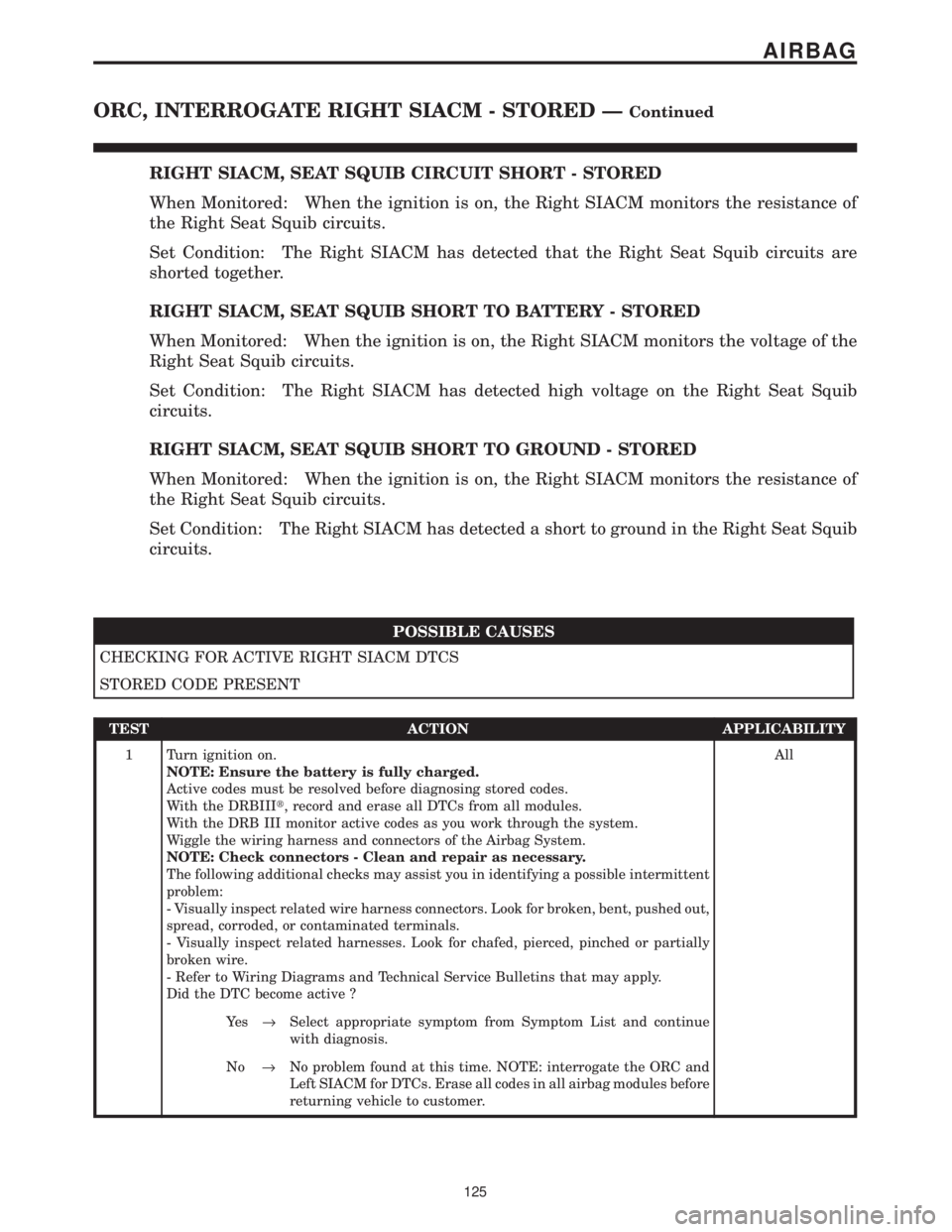
RIGHT SIACM, SEAT SQUIB CIRCUIT SHORT - STORED
When Monitored: When the ignition is on, the Right SIACM monitors the resistance of
the Right Seat Squib circuits.
Set Condition: The Right SIACM has detected that the Right Seat Squib circuits are
shorted together.
RIGHT SIACM, SEAT SQUIB SHORT TO BATTERY - STORED
When Monitored: When the ignition is on, the Right SIACM monitors the voltage of the
Right Seat Squib circuits.
Set Condition: The Right SIACM has detected high voltage on the Right Seat Squib
circuits.
RIGHT SIACM, SEAT SQUIB SHORT TO GROUND - STORED
When Monitored: When the ignition is on, the Right SIACM monitors the resistance of
the Right Seat Squib circuits.
Set Condition: The Right SIACM has detected a short to ground in the Right Seat Squib
circuits.
POSSIBLE CAUSES
CHECKING FOR ACTIVE RIGHT SIACM DTCS
STORED CODE PRESENT
TEST ACTION APPLICABILITY
1 Turn ignition on.
NOTE: Ensure the battery is fully charged.
Active codes must be resolved before diagnosing stored codes.
With the DRBIIIt, record and erase all DTCs from all modules.
With the DRB III monitor active codes as you work through the system.
Wiggle the wiring harness and connectors of the Airbag System.
NOTE: Check connectors - Clean and repair as necessary.
The following additional checks may assist you in identifying a possible intermittent
problem:
- Visually inspect related wire harness connectors. Look for broken, bent, pushed out,
spread, corroded, or contaminated terminals.
- Visually inspect related harnesses. Look for chafed, pierced, pinched or partially
broken wire.
- Refer to Wiring Diagrams and Technical Service Bulletins that may apply.
Did the DTC become active ?All
Ye s®Select appropriate symptom from Symptom List and continue
with diagnosis.
No®No problem found at this time. NOTE: interrogate the ORC and
Left SIACM for DTCs. Erase all codes in all airbag modules before
returning vehicle to customer.
125
AIRBAG
ORC, INTERROGATE RIGHT SIACM - STORED ÐContinued
Page 159 of 4284
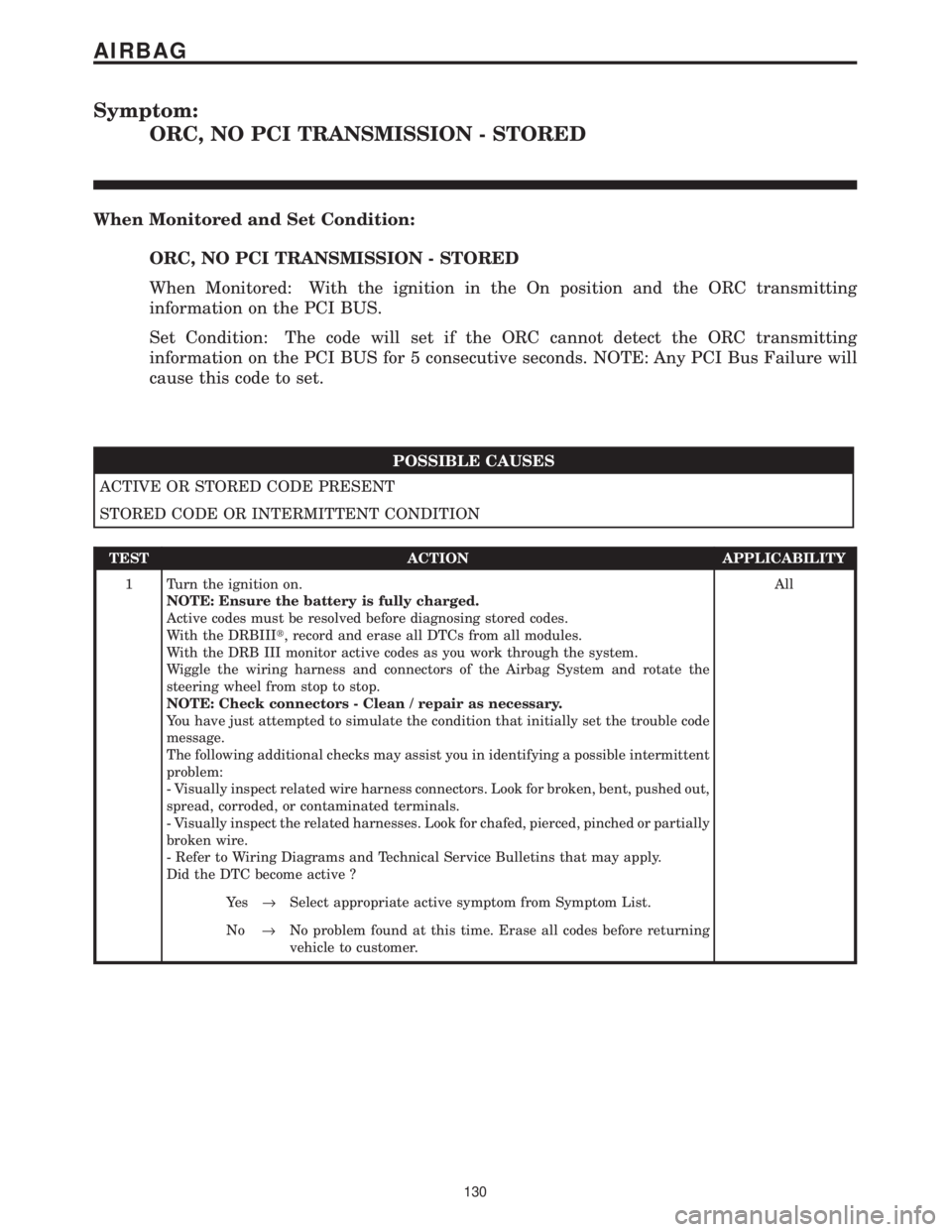
Symptom:
ORC, NO PCI TRANSMISSION - STORED
When Monitored and Set Condition:
ORC, NO PCI TRANSMISSION - STORED
When Monitored: With the ignition in the On position and the ORC transmitting
information on the PCI BUS.
Set Condition: The code will set if the ORC cannot detect the ORC transmitting
information on the PCI BUS for 5 consecutive seconds. NOTE: Any PCI Bus Failure will
cause this code to set.
POSSIBLE CAUSES
ACTIVE OR STORED CODE PRESENT
STORED CODE OR INTERMITTENT CONDITION
TEST ACTION APPLICABILITY
1 Turn the ignition on.
NOTE: Ensure the battery is fully charged.
Active codes must be resolved before diagnosing stored codes.
With the DRBIIIt, record and erase all DTCs from all modules.
With the DRB III monitor active codes as you work through the system.
Wiggle the wiring harness and connectors of the Airbag System and rotate the
steering wheel from stop to stop.
NOTE: Check connectors - Clean / repair as necessary.
You have just attempted to simulate the condition that initially set the trouble code
message.
The following additional checks may assist you in identifying a possible intermittent
problem:
- Visually inspect related wire harness connectors. Look for broken, bent, pushed out,
spread, corroded, or contaminated terminals.
- Visually inspect the related harnesses. Look for chafed, pierced, pinched or partially
broken wire.
- Refer to Wiring Diagrams and Technical Service Bulletins that may apply.
Did the DTC become active ?All
Ye s®Select appropriate active symptom from Symptom List.
No®No problem found at this time. Erase all codes before returning
vehicle to customer.
130
AIRBAG
Page 218 of 4284
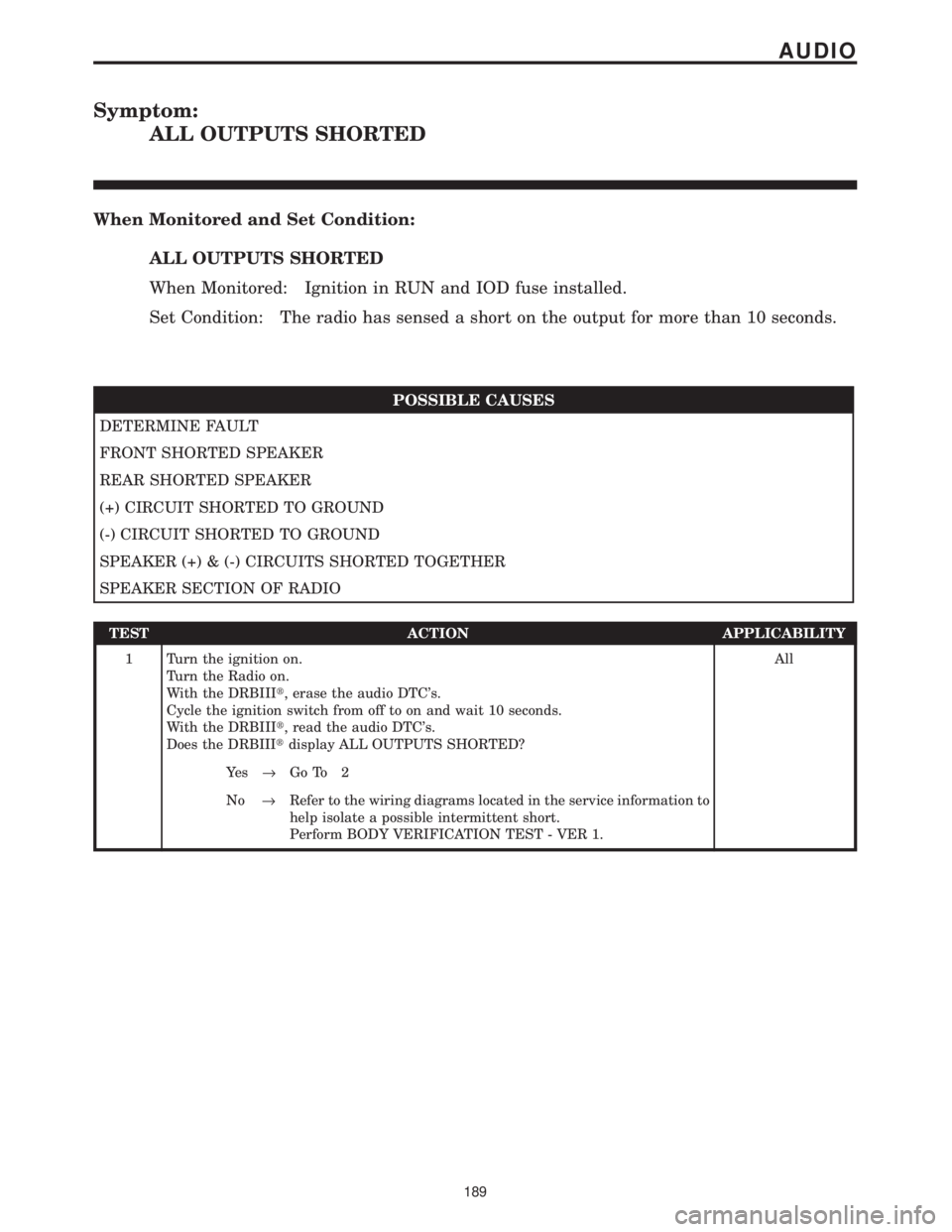
Symptom:
ALL OUTPUTS SHORTED
When Monitored and Set Condition:
ALL OUTPUTS SHORTED
When Monitored: Ignition in RUN and IOD fuse installed.
Set Condition: The radio has sensed a short on the output for more than 10 seconds.
POSSIBLE CAUSES
DETERMINE FAULT
FRONT SHORTED SPEAKER
REAR SHORTED SPEAKER
(+) CIRCUIT SHORTED TO GROUND
(-) CIRCUIT SHORTED TO GROUND
SPEAKER (+) & (-) CIRCUITS SHORTED TOGETHER
SPEAKER SECTION OF RADIO
TEST ACTION APPLICABILITY
1 Turn the ignition on.
Turn the Radio on.
With the DRBIIIt, erase the audio DTC's.
Cycle the ignition switch from off to on and wait 10 seconds.
With the DRBIIIt, read the audio DTC's.
Does the DRBIIItdisplay ALL OUTPUTS SHORTED?All
Ye s®Go To 2
No®Refer to the wiring diagrams located in the service information to
help isolate a possible intermittent short.
Perform BODY VERIFICATION TEST - VER 1.
189
AUDIO
Page 230 of 4284
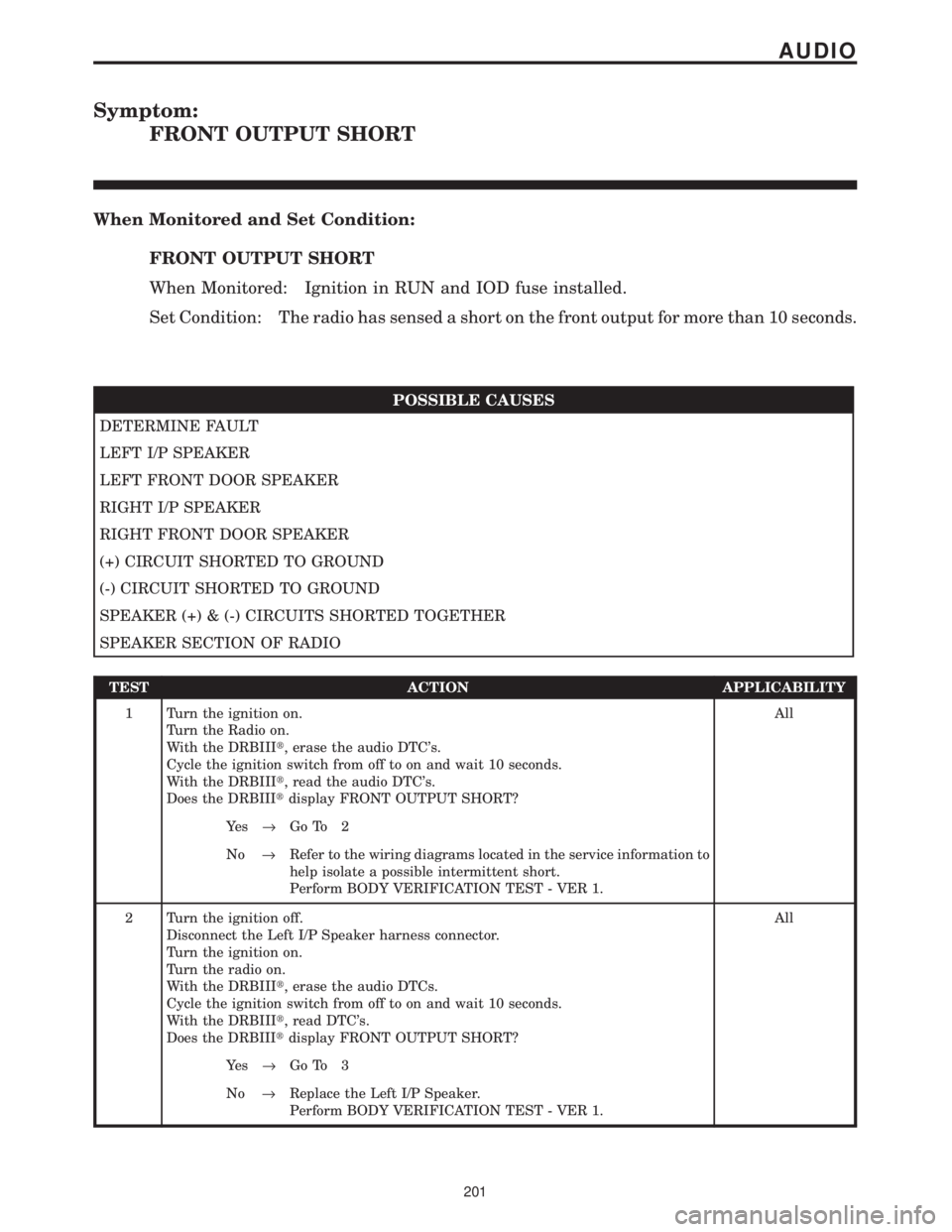
Symptom:
FRONT OUTPUT SHORT
When Monitored and Set Condition:
FRONT OUTPUT SHORT
When Monitored: Ignition in RUN and IOD fuse installed.
Set Condition: The radio has sensed a short on the front output for more than 10 seconds.
POSSIBLE CAUSES
DETERMINE FAULT
LEFT I/P SPEAKER
LEFT FRONT DOOR SPEAKER
RIGHT I/P SPEAKER
RIGHT FRONT DOOR SPEAKER
(+) CIRCUIT SHORTED TO GROUND
(-) CIRCUIT SHORTED TO GROUND
SPEAKER (+) & (-) CIRCUITS SHORTED TOGETHER
SPEAKER SECTION OF RADIO
TEST ACTION APPLICABILITY
1 Turn the ignition on.
Turn the Radio on.
With the DRBIIIt, erase the audio DTC's.
Cycle the ignition switch from off to on and wait 10 seconds.
With the DRBIIIt, read the audio DTC's.
Does the DRBIIItdisplay FRONT OUTPUT SHORT?All
Ye s®Go To 2
No®Refer to the wiring diagrams located in the service information to
help isolate a possible intermittent short.
Perform BODY VERIFICATION TEST - VER 1.
2 Turn the ignition off.
Disconnect the Left I/P Speaker harness connector.
Turn the ignition on.
Turn the radio on.
With the DRBIIIt, erase the audio DTCs.
Cycle the ignition switch from off to on and wait 10 seconds.
With the DRBIIIt, read DTC's.
Does the DRBIIItdisplay FRONT OUTPUT SHORT?All
Ye s®Go To 3
No®Replace the Left I/P Speaker.
Perform BODY VERIFICATION TEST - VER 1.
201
AUDIO
Page 233 of 4284
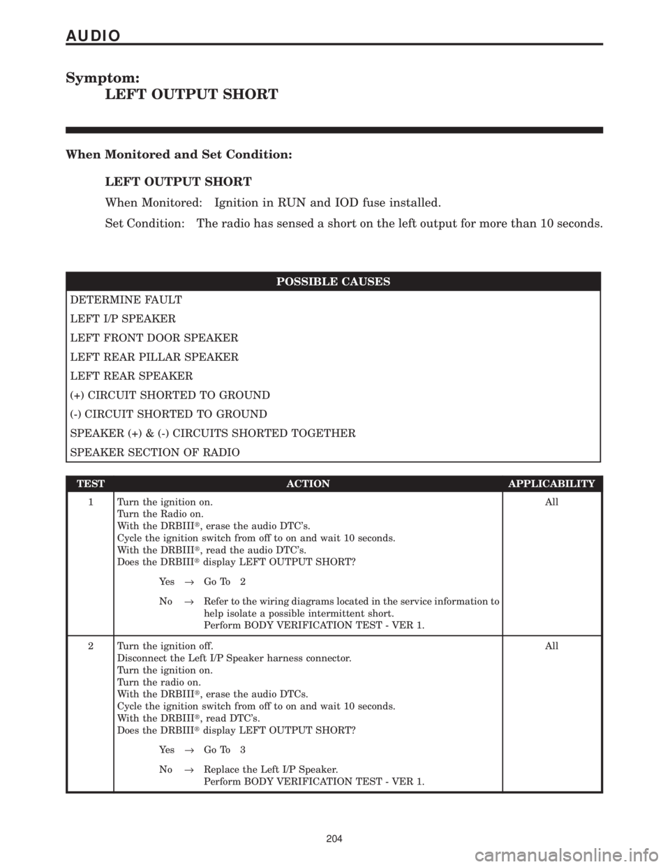
Symptom:
LEFT OUTPUT SHORT
When Monitored and Set Condition:
LEFT OUTPUT SHORT
When Monitored: Ignition in RUN and IOD fuse installed.
Set Condition: The radio has sensed a short on the left output for more than 10 seconds.
POSSIBLE CAUSES
DETERMINE FAULT
LEFT I/P SPEAKER
LEFT FRONT DOOR SPEAKER
LEFT REAR PILLAR SPEAKER
LEFT REAR SPEAKER
(+) CIRCUIT SHORTED TO GROUND
(-) CIRCUIT SHORTED TO GROUND
SPEAKER (+) & (-) CIRCUITS SHORTED TOGETHER
SPEAKER SECTION OF RADIO
TEST ACTION APPLICABILITY
1 Turn the ignition on.
Turn the Radio on.
With the DRBIIIt, erase the audio DTC's.
Cycle the ignition switch from off to on and wait 10 seconds.
With the DRBIIIt, read the audio DTC's.
Does the DRBIIItdisplay LEFT OUTPUT SHORT?All
Ye s®Go To 2
No®Refer to the wiring diagrams located in the service information to
help isolate a possible intermittent short.
Perform BODY VERIFICATION TEST - VER 1.
2 Turn the ignition off.
Disconnect the Left I/P Speaker harness connector.
Turn the ignition on.
Turn the radio on.
With the DRBIIIt, erase the audio DTCs.
Cycle the ignition switch from off to on and wait 10 seconds.
With the DRBIIIt, read DTC's.
Does the DRBIIItdisplay LEFT OUTPUT SHORT?All
Ye s®Go To 3
No®Replace the Left I/P Speaker.
Perform BODY VERIFICATION TEST - VER 1.
204
AUDIO
Page 236 of 4284
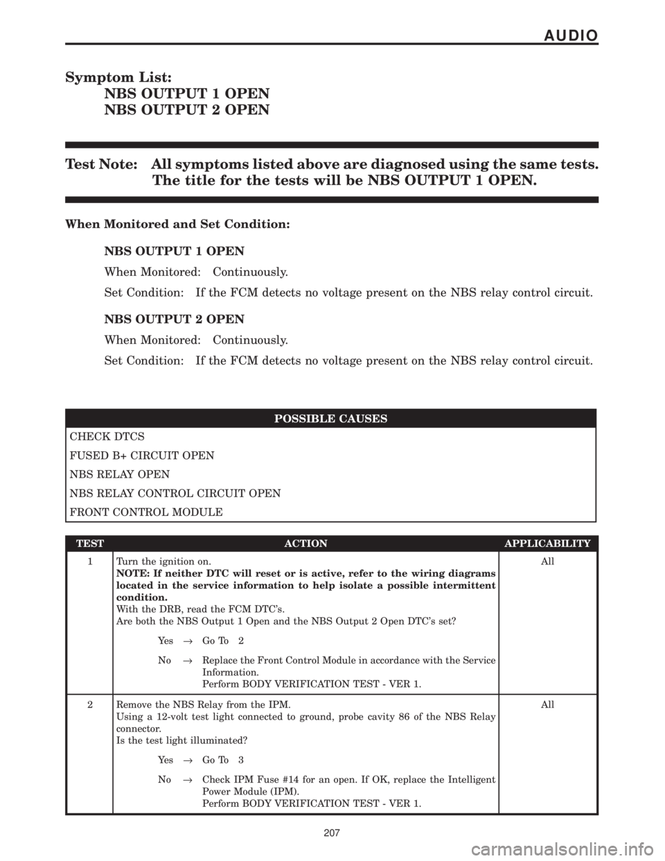
Symptom List:
NBS OUTPUT 1 OPEN
NBS OUTPUT 2 OPEN
Test Note: All symptoms listed above are diagnosed using the same tests.
The title for the tests will be NBS OUTPUT 1 OPEN.
When Monitored and Set Condition:
NBS OUTPUT 1 OPEN
When Monitored: Continuously.
Set Condition: If the FCM detects no voltage present on the NBS relay control circuit.
NBS OUTPUT 2 OPEN
When Monitored: Continuously.
Set Condition: If the FCM detects no voltage present on the NBS relay control circuit.
POSSIBLE CAUSES
CHECK DTCS
FUSED B+ CIRCUIT OPEN
NBS RELAY OPEN
NBS RELAY CONTROL CIRCUIT OPEN
FRONT CONTROL MODULE
TEST ACTION APPLICABILITY
1 Turn the ignition on.
NOTE: If neither DTC will reset or is active, refer to the wiring diagrams
located in the service information to help isolate a possible intermittent
condition.
With the DRB, read the FCM DTC's.
Are both the NBS Output 1 Open and the NBS Output 2 Open DTC's set?All
Ye s®Go To 2
No®Replace the Front Control Module in accordance with the Service
Information.
Perform BODY VERIFICATION TEST - VER 1.
2 Remove the NBS Relay from the IPM.
Using a 12-volt test light connected to ground, probe cavity 86 of the NBS Relay
connector.
Is the test light illuminated?All
Ye s®Go To 3
No®Check IPM Fuse #14 for an open. If OK, replace the Intelligent
Power Module (IPM).
Perform BODY VERIFICATION TEST - VER 1.
207
AUDIO