run flat CHRYSLER VOYAGER 2001 Service Manual
[x] Cancel search | Manufacturer: CHRYSLER, Model Year: 2001, Model line: VOYAGER, Model: CHRYSLER VOYAGER 2001Pages: 4284, PDF Size: 83.53 MB
Page 31 of 4284
mitted on the bus even though a module may not
require all information to perform its function. It
will only respond to messages ªaddressedº to it
through binary coding process. This method of data
transmission significantly reduces the complexity
of the wiring in the vehicle and the size of wiring
harnesses. All of the information about the func-
tioning of all the systems is organized, controlled,
and communicated by the PCI bus, which is de-
scribed in the Communication Section of this gen-
eral information.
3.1 AIRBAG SYSTEM/OCCUPANT
RESTRAINT CONTROLLER SYSTEM
The 2001 Minivan Airbag System contain the
following components: Occupant Restraint Control-
ler (ORC), Airbag Warning Indicator, Clockspring,
Driver and Passenger Airbags, Seat belt Tensioners
(SBT), Hall-effect Seat Belt Switches (SBS), Left
and Right Side Airbag Control Module (SIACM),
and Seat (mounted side) Airbags.
The Occupant Restraint Controller (ORC) is a
new type of Airbag Control Module (ACM) that
supports staged airbag deployment. Staged deploy-
ment is the ability to trigger airbag system squib
inflators all at once or individually as needed to
provide the appropriate restraint for the severity of
the impact. The ORC has four major functions: PCI
Bus communications, onboard diagnostics, impact
sensing, and component deployment. The ORC also
contains an energy-storage capacitor. This capaci-
tor stores enough electrical energy to deploy the
front airbag components for two seconds following a
battery disconnect or failure during an impact. The
ORC is secured to the floor panel transmission
tunnel below the instrument panel inside the vehi-
cle. The ORC cannot be repaired or adjusted and
must be replaced.
The ORC sends and/or receives PCI Bus mes-
sages with the Instrument Cluster (MIC), Body
Control Module (BCM), and Powertrain Control
Module (PCM). Diagnostic trouble codes will be set
if the communication with these modules is lost or
contains invalid information.
The microprocessor in the ORC monitors the
impact sensor signal and the airbag system electri-
cal circuits to determine the system readiness. The
ORC also monitors bus messages from both SIACM.
If the ORC detects a monitored system fault or
SIACM fault, it sends a message to the instrument
cluster via PCI bus to turn on the airbag warning
indicator. The ORC can set both active and stored
diagnostic trouble codes to aid in the diagnosing
system problems. See ORC/SIACM DIAGNOSTIC
TROUBLE CODES in this section.
The ORC has an internal accelerometer that
senses the rate of vehicle deceleration, which pro-vides verification of the direction and severity of an
impact. A pre-programmed decision algorithm in
the ORC microprocessor determines when the de-
celeration rate is severe enough to require airbag
system protection. The Occupant Restraint Control-
ler (ORC) also uses the driver and front passenger
seat belt switch status (buckled or unbuckled) as
inputs to determine the level of airbag deployment,
low, medium, or high as well as whether or not the
seat belt tensioners should deploy. The ORC also
uses the crash severity to determine the level of
driver and front passenger deployment, low me-
dium or high. When the programmed conditions are
met, the ORC sends an electrical signal to deploy
the appropriate airbag system components.WARNING: THE AIRBAG SYSTEM IS A
SENSITIVE, COMPLEX ELECTRO-
MECHANICAL UNIT. BEFORE ATTEMPTING
TO DIAGNOSE OR SERVICE ANY AIRBAG
SYSTEM OR RELATED STEERING WHEEL,
STEERING COLUMN, OR INSTRUMENT
PANEL COMPONENTS YOU MUST FIRST
DISCONNECT AND ISOLATE THE BATTERY
NEGATIVE (GROUND) CABLE. WAIT TWO
MINUTES FOR THE SYSTEM CAPACITOR TO
DISCHARGE BEFORE FURTHER SYSTEM
SERVICE. THIS IS THE ONLY SURE WAY TO
DISABLE THE AIRBAG SYSTEM. FAILURE
TO DO THIS COULD RESULT IS ACCIDENTAL
AIRBAG DEPLOYMENT AND POSSIBLE
PERSONAL INJURY. NEVER STRIKE OR
KICK THE AIRBAG CONTROL MODULE, AS
IT CAN DAMAGE THE IMPACT SENSOR OR
AFFECT ITS CALIBRATION. IF AN AIRBAG
CONTROL MODULE IS ACCIDENTALLY
DROPPED DURING SERVICE, THE MODULE
MUST BE SCRAPPED AND REPLACED WITH
A NEW UNIT.
The airbag warning lamp is the only point at
which the customer can observe symptoms of a
system malfunction. Whenever the ignition key is
turned to the run or start position, the MIC per-
forms a lamp check by turning the airbag warning
indicator on for 6-8 seconds. After the lamp check, if
the indicator turns on, it means that the ORC has
checked the system and found it to be free of
discernible malfunctions. If the lamp remains on,
there could be an active fault in the system or the
MIC lamp circuit may be internally shorted to
ground. If the lamp comes on and stays on for a
period longer than 6-8 seconds then goes off, there
is usually an intermittent problem in the system.
2
GENERAL INFORMATION
Page 35 of 4284
if the system is functioning properly. If the test
finds a problem the SIACM will set both active and
stored diagnostic trouble codes. If a DTC is active
the SIACM will request that the airbag warning
lamp be turned on. The results of the system test
are transmitted on the PCI Bus to the ORC once
each second or on change in lamp state. If the
warning lamp status message from the either SI-
ACM contains a lamp on request, the ORC will set
an active DTC. At the same time as the DTC is set
the ORC sends a PCI Bus message to the mechan-
ical instrument cluster (MIC) requesting the airbag
warning lamp be turned on. Observe all ORC warn-
ing and caution statements when servicing or han-
dling the SIACM. SIACM are not repairable and
must be replaced if they are dropped.
WARNING: THE AIRBAG SYSTEM IS A
SENSITIVE, COMPLEX ELECTRO-
MECHANICAL UNIT. BEFORE ATTEMPTING
TO DIAGNOSE OR SERVICE ANY AIRBAG
SYSTEM OR RELATED STEERING WHEEL,
STEERING COLUMN, OR INSTRUMENT
PANEL COMPONENTS YOU MUST FIRST
DISCONNECT AND ISOLATE THE BATTERY
NEGATIVE (GROUND) CABLE. WAIT TWO
MINUTES FOR THE SYSTEM CAPACITOR TO
DISCHARGE BEFORE FURTHER SYSTEM
SERVICE. THIS IS THE ONLY SURE WAY TO
DISABLE THE AIRBAG SYSTEM. FAILURE
TO DO THIS COULD RESULT IN ACCIDENTAL
AIRBAG DEPLOYMENT AND POSSIBLE
PERSONAL INJURY. NEVER STRIKE OR
KICK THE AIRBAG CONTROL MODULE, AS
IT CAN DAMAGE THE IMPACT SENSOR OR
AFFECT ITS CALIBRATION. IF AN AIRBAG
CONTROL MODULE IS ACCIDENTALLY
DROPPED DURING SERVICE, THE MODULE
MUST BE SCRAPPED AND REPLACED WITH
A NEW UNIT.
The airbag warning lamp is the only point at
which the customer can observe symptoms of a
system malfunction. Whenever the ignition key is
turned to the run or start position, the MIC per-
forms a lamp check by turning the airbag warning
indicator on for 6-8 seconds. After the lamp check, if
the indicator turns on, it means that the ORC has
checked the system and found it to be free of
discernible malfuctions. If the lamp remains on,
there could be an active fault in the system or the
MIC lamp circuit may be internally shorted to
ground. If the lamp comes on and stays on for a
period longer than 6-8 seconds then goes off, there
is usually an intermittent problem in the system.
3.1.7 SEAT AIRBAGS (SAB)
The left and right seat airbag modules are located
in the outboard end of the front seat backs. The
airbag module contains a bag, an inflator (a small
canister of highly compressed argon gas) and a
mounting bracket. The seat airbag module cannot
be repaired and must be replaced if deployed or in
any way damaged. When supplied with the proper
electrical signal the inflator seals the hole in the
airbag cushion so it can discharge the compressed
gas it contains directly into the cushion. Upon
deployment, the seat back trim cover will tear open
and allow the seat airbag to fully deploy between
the seat and the door.
WARNING: SEAT AIRBAG CONTAINS ARGON
GAS PRESSURIZED TO OVER 17236.89 Kpa
(2500 PSI). DO NOT ATTEMPT TO
DISMANTLE AN AIRBAG MODULE OR
TAMPER WITH ITS INFLATOR. DO NOT
PUNCTURE, INCINERATE, OR BRING INTO
CONTACT WITH ELECTRICITY. DO NOT
STORE AT TEMPERATURE EXCEEDING 93ÉC
(200ÉF). REPLACE AIRBAG SYSTEM
COMPONENTS ONLY WITH PARTS
SPECIFIED IN THE CHRYSLER MOPAR
PARTS CATALOG. SUBSTITUTE PARTS MAY
APPEAR INTERCHANGEABLE, BUT
INTERNAL DIFFERENCES MAY RESULT IN
INFERIOR OCCUPANT PROTECTION. THE
FASTENERS, SCREWS, AND BOLTS
ORIGINALLY USED FOR THE AIRBAG
SYSTEM COMPONENTS HAVE SPECIAL
COATINGS AND ARE SPECIFICALLY
DESIGNED FOR THE AIRBAG SYSTEM. THEY
MUST NEVER BE REPLACED WITH ANY
SUBSTITUTES. ANY TIME A NEW FASTENER
IS NEEDED, REPLACE IT WITH THE
CORRECT FASTENERS PROVIDED IN THE
SERVICE PACKAGE OR SPECIFIED IN THE
MOPAR PARTS CATALOG.
3.1.8 ORC/SIACM DIAGNOSTIC TROUBLE
CODES
Airbag diagnostic trouble codes consist of active
and stored codes. If more than one code exists,
diagnostic priority should be given to the active
codes. Each diagnostic trouble code is diagnosed by
following a specific testing procedure. The diagnos-
tic test procedures contain step-by-step instructions
for determining the cause of the trouble codes. It is
not necessary to perform all of the tests in this book
to diagnose an individual code. Always begin by
reading the diagnostic trouble codes using the DRB.
Always begin diagnostic with the Table of Contents
6
GENERAL INFORMATION
Page 1160 of 4284
²three power feeds: valves, pump and microproces-
sor
²brake switch
²traction control switch
The CAB outputs include the following:
²ABS warning indicator actuation
²12 volts power to wheel speed sensors
²eight valves
²ten valves with traction control
²diagnostic communication
²PCI bus communication
²traction control lamp illumination
3.3.3 HYDRAULIC CONTROL UNIT
The hydraulic control unit (HCU) contains the
valve block assembly, two accumulators, and pump/
motor assembly. The HCU is attached to the CAB.
Valve Block Assembly:The valve block assem-
bly contains valves with four inlet valves and four
outlet valves. The inlet valves are spring-loaded in
the open position and the outlet valves are spring
loaded in the closed position. During an antilock
stop, these valves are cycled to maintain the proper
slip ratio for each wheel. If a wheel detects slip, the
inlet valve is closed to prevent and further pressure
increase. Then the outlet valve is opened to release
the pressure to the accumulators until the wheel is
no longer slipping. Once the wheel is no longer
slipping, the outlet valve is closed and the inlet
valve is opened to reapply pressure. If the wheel is
decelerating within its predetermined limits (prop-
er slip ratio), the inlet valve will close to hold the
pressure constant. On vehicles which are equipped
with a traction control system, there are two addi-
tional valves that isolate the master cylinder and
rear wheels. During a traction control event the
brakes are applied to reduce wheel slippage.
Pump Motor Assembly:The pump motor as-
sembly provides the extra amount of fluid needed
during antilock braking. The pump is supplied fluid
that is released to the accumulators when the outlet
valve is opened during an antilock stop. The pump
is also used to drain the accumulator circuits after
the antilock stop is complete. The pump is operated
by an integral electric motor. This DC-type motor is
controlled by the CAB. The CAB may turn on the
pump motor when an antilock stop is detected. The
pump continues to run during the antilock stop and
is turned off after the stop is complete. Under some
conditions, the pump motor will run to drain the
accumulators during the next drive off. The CAB
monitors the pump motor operation internally.
Accumulators:The accumulators provide tem-
porary fluid storage during an antilock stop and are
drained by the pump motor.
3.3.4 SWITCHES/SENSORS
Master Cylinder:The master cylinder is a stan-
dard tandem compensating port design for ABS and
non ABS systems. Traction control vehicles use a
dual center port master cylinder. For proper trac-
tion control operation the standard master cylinder
must not be used.
A fluid level switch is located in the master
cylinder fluid reservoir. The switch closes when a
low fluid level is detected. The fluid level switch
turns on the brake warning indicator by grounding
the indicator circuit. This switch does not disable
the ABS system.
Wheel Speed Sensors and Tone Wheels:One
active wheel speed sensor (WSS) is located at each
wheel and sends a small signal to the control
module (CAB). This signal is generated when a
toothed sensor ring (tone wheel) passes by a station-
ary wheel speed sensor. The CAB converts the
signals into digital signals for each wheel.
Because of internal circuitry, correct wheel speed
sensor function cannot be determined by a continu-
ity or resistance check through the sensor.
The front wheel speed sensor is attached to a boss
in the steering knuckle. The tone wheel is an
integral part of the front axle shaft. The rear speed
sensor is mounted though the bearing cover and the
rear tone wheel is an integral part of the rear
bearing hub. The wheel speed sensor air gap is not
adjustable. Refer to the service manual for wheel
speed sensor air gap and resistance specifications.
The four wheel speed sensors are serviced indi-
vidually. The front tone wheels are serviced as an
assembly with the outer constant velocity (C.V.)
joint housing. The rear tone wheels are serviced as
an assembly.
Correct antilock system operation is dependent
on tone wheel speed signals from the wheel speed
sensors. The vehicle's wheels and tires should all be
the same size and type to generate accurate signals.
In addition, the tires should be inflated to the
recommended pressure for optimum system opera-
tion. Variation in wheel and tire size or significant
variations in inflation pressure can produce inaccu-
rate wheel speed signals; however, the system will
continue to function when using the mini-spare.
3.3.5 SYSTEM INITIALIZATION
System initialization starts when the key is
turned to ªrunº. At this point, the CAB performs a
complete self-check of all electrical components in
the antilock systems.
Between 8-17 km/h (5-10 mph), a dynamic test is
performed. This will momentarily cycle the inlet
and outlet valves, check wheel speed sensor cir-
cuitry, and run the pump motor at 25 km/h (15
mph). The CAB will try to test the pump motor. If
3
GENERAL INFORMATION
Page 1567 of 4284
CONDITION POSSIBLE CAUSES CORRECTION
Excessive Steering Free
Play1. Incorrect Steering Gear Adjustment 1. Adjust Or Replace Steering Gear
2. Worn or loose tie rod ends 2. Replace or tighten tie rod ends
3. Loose steering gear mounting bolts 3. Tighten steering gear bolts to specified
torque
4. Loose or worn steering shaft coupler 4. Replace steering shaft coupler
Excessive Steering Effort 1. Low tire pressure 1. Inflate all tires to recommended
pressure
2. Lack of lubricant in steering gear 2. Replace steering gear
3. Low power steering fluid level 3. Fill power steering fluid reservoir to
correct level
4. Loose power steering pump drive
belt4. Correctly adjust power steering pump
drive belt
5. Lack of lubricant in ball joints 5. Lubricate or replace ball joints
6. Steering gear malfunction 6. Replace steering gear
7. Lack of lubricant in steering coupler 7. Replace steering coupler
STANDARD PROCEDURE - WHEEL ALIGNMENT
PRE-WHEEL ALIGNMENT INSPECTION
Before any attempt is made to change or correct
the wheel alignment, the following inspection and
necessary corrections must be made to ensure proper
alignment.
(1) Verify that the fuel tank is full of fuel. If the
tank is not full, the reduction in weight will affect
the curb height of the vehicle and the alignment
angles.
(2) The passenger and luggage compartments of
the vehicle should be free of any load that is not fac-
tory equipment.
(3) Check the tires on the vehicle. All tires must be
the same size and in good condition with approxi-
mately the same amount of tread wear. Inflate all
the tires to the recommended air pressure.
(4) Check the front wheel and tire assemblies for
excessive radial runout.
(5) Inspect lower ball joints and all steering link-
age for looseness, binding, wear or damage. Repair as
necessary.
(6) Check suspension fasteners for proper torque
and retighten as necessary.
(7) Inspect all suspension component rubber bush-
ings for signs of wear or deterioration. Replace any
faulty bushings or components before aligning the
vehicle.
(8) Check the vehicle's curb height to verify it is
within specifications. Refer to Curb Height Measure-
ment.
WHEEL ALIGNMENT SETUP
(1) Position the vehicle on an alignment rack.
(2) Install all required alignment equipment on
the vehicle per the alignment equipment manufactur-
er's instructions. On this vehicle, a four-wheel align-
ment is recommended.
NOTE: Prior to reading the vehicle's alignment
readouts, the front and rear of vehicle should be
jounced. Induce jounce (rear first, then front) by
grasping the center of the bumper and jouncing
each end of vehicle an equal number of times. The
bumper should always be released when vehicle is
at the bottom of the jounce cycle.
(3) Read the vehicle's current front and rear align-
ment settings. Compare the vehicle's current align-
ment settings to the vehicle specifications for camber,
caster and toe-in. (Refer to 2 - SUSPENSION/
WHEEL ALIGNMENT - SPECIFICATIONS)
(4) If front camber and caster are not within spec-
ifications, proceed to CAMBER AND CASTER below.
If caster and camber are within specifications, pro-
ceed to TOE which can be found following CAMBER
AND CASTER. Rear camber, caster and toe are not
adjustable. If found not to be within specifications,
reinspect for damaged suspension or body compo-
nents and replace as necessary.
CAMBER AND CASTER
Camber and caster settings on this vehicle are
determined at the time the vehicle is designed, by
the location of the vehicle's suspension components.
This is referred to as NET BUILD. The result is no
RSWHEEL ALIGNMENT2-51
WHEEL ALIGNMENT (Continued)
Page 1614 of 4284
lock the front wheels first. Any torque transfer from
the rear axle to the front axle disturbs the ABS/brak-
ing system and causes potential instabilities on a
slippery surface. The BOC de-couples the rear driv-
eline as soon the rear wheels begin to spin faster
than the front wheels (front wheels locked) in order
to provide increased braking stability. Furthermore
the BOC also reduces the likelihood of throttle off
over-steer during cornering. In a throttle off maneu-
ver, the BOC once again de-couples the rear driveline
forcing all the engine brake torque to the front
wheels. This eliminates the chance of lateral slip on
the rear axle and increases it on the front. The vehi-
cle will therefore tend to understeer, a situation
which is considered easier to manage in most circum-
stances. During this maneuver, and during the ABS
braking event, the BOC does not transmit torque
through to the rear wheels. The rear driveline mod-
ule, with the BOC, will perform the same as a front
wheel drive vehicle during these events. The gear
ratio offset between the front and rear differentials
force the BOC into the overrunning mode most of the
time. This allows BOC to significantly reduce the
rolling resistance of the vehicle, which improves fuel
consumption, allows the downsizing of the driveline
components, and prevents the PTU and propshaft
joints from overheating.
OPERATION
In order to achieve all-wheel drive operation in
reverse, the overrunning clutch locking functional
direction must be reversible. The bi-directional over-
running clutch (BOC) changes the operational mode
direction depending on the propeller shaft direction.
The propeller shaft rotates in the clockwise (when
viewed from the front) direction when the vehicle is
moving forward, which indexes the BOC to the for-
ward overrunning position. When the vehicle is in
reverse, the propeller shaft will rotate counter-clock-
wise and index the BOC to the reverse overrunning
position.
The BOC acts as a mechanical stator. It is active
(transmitting torque), or it is not active and in over-
running mode (not transmitting torque). This ªall or
nothingº approach to torque transfer would cause a
sudden application of all available power to the rear
wheels, which is not desirable. Therefore it is run in
series with a viscous coupler to smooth, dampen, and
limit the transmission of torque to the rear axle and
to prevent a step style torque input to the rear axle.
STEADY STATE, LOW TO MODERATE SPEED, NO
FRONT WHEEL SLIP, FORWARD DIRECTION
During normal driving conditions, (no wheel slip),
the inner shaft (front axle) and outer race (viscous
coupler) are running at different speeds due to the
different gear ratios between the front and rear dif-
ferentials. In this condition, the outer race is always
spinning faster (overdriving between 5-32 rpm) than
the inner shaft. When the BOC (Fig. 29) is running
under these conditions, at low vehicle speeds the
drag shoes and the cage keep the rollers up on the
left side (forward side) of the inner shaft flats. This is
what is known as ªoverrunning mode.º Notice that
when the clutch is in overrunning mode, the rollers
are spinning clockwise and with the outer race, thus
no torque is being transferred.
NOTE: Low speed, forward and reverse operation is
identical, just in opposite directions. (Fig. 29)
shows forward direction in reverse the rollers are
on the other side of the flats due to a reversal of
the cage force.
TRANSIENT CONDITION (BOC LOCKED), FRONT
WHEEL SLIP, FORWARD DIRECTION
When the front wheels lose traction and begin to
slip, the propeller shaft and rear axle pinion speed
difference decreases to zero. At this point the input
shaft (cam) becomes the driving member of the BOC
(Fig. 30), compressing the rollers against the outer
race. This locks the input shaft with the outer race
and transmits torque to the housing of the viscous
coupler, that in turn transmits torque to the rear
axle pinion. It should also be noted that when the
device is locked, the inner shaft and the outer race
are rotating at the same speed. The rollers are
pinched at this point and will stay locked until a
torque reversal (no front wheel slip) occurs. When
locked, the viscous coupler slips during the torque
transfer and the amount of torque transferred is
dependent on the coupling characteristic and the
amount of front wheel slip.
3 - 38 REAR DRIVELINE MODULERS
BI-DIRECTIONAL OVERRUNNING CLUTCH (Continued)
Page 1616 of 4284
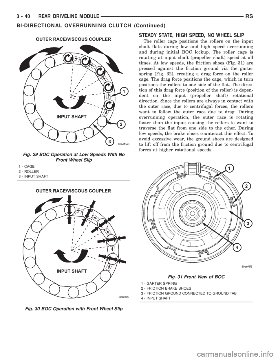
STEADY STATE, HIGH SPEED, NO WHEEL SLIP
The roller cage positions the rollers on the input
shaft flats during low and high speed overrunning
and during initial BOC lockup. The roller cage is
rotating at input shaft (propeller shaft) speed at all
times. At low speeds, the friction shoes (Fig. 31) are
pressed against the friction ground via the garter
spring (Fig. 32), creating a drag force on the roller
cage. The drag force positions the cage, which in turn
positions the rollers to one side of the flat. The direc-
tion of this drag force (position of the roller) is depen-
dent on the input (propeller shaft) rotational
direction. Since the rollers are always in contact with
the outer race, due to centrifugal forces, the rollers
want to follow the outer race due to drag. During
overrunning operation, the outer race is rotating
faster than the input; causing the rollers to want to
traverse the flat from one side to the other. During
low speeds, the brake shoes counteract this effect. To
avoid excessive wear, the ground shoes are designed
to lift off from the friction ground due to centrifugal
forces at higher rotational speeds.
Fig. 29 BOC Operation at Low Speeds With No
Front Wheel Slip
1 - CAGE
2 - ROLLER
3 - INPUT SHAFT
Fig. 30 BOC Operation with Front Wheel Slip
Fig. 31 Front View of BOC
1 - GARTER SPRING
2 - FRICTION BRAKE SHOES
3 - FRICTION GROUND CONNECTED TO GROUND TAB
4 - INPUT SHAFT
3 - 40 REAR DRIVELINE MODULERS
BI-DIRECTIONAL OVERRUNNING CLUTCH (Continued)
Page 1617 of 4284
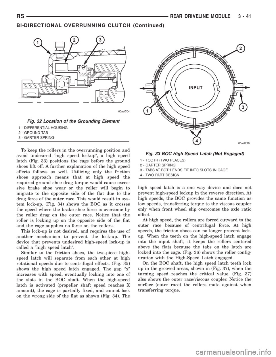
To keep the rollers in the overrunning position and
avoid undesired9high speed lockup9, a high speed
latch (Fig. 33) positions the cage before the ground
shoes lift off. A further explanation of the high speed
effects follows as well. Utilizing only the friction
shoes approach means that at high speed the
required ground shoe drag torque would cause exces-
sive brake shoe wear or the roller will begin to
migrate to the opposite side of the flat due to the
drag force of the outer race. This would result in sys-
tem lock-up. (Fig. 34) shows the BOC as it crosses
the speed where the brake shoe force is overcome by
the roller drag on the outer race. Notice that the
roller is locking up on the opposite side of the flat
and the cage supplies no force on the rollers.
This lock-up is not desired, and requires the use of
another mechanism to prevent the lock-up. The
device that prevents undesired high-speed lock-up is
called a9high speed latch9.
Similar to the friction shoes, the two-piece high-
speed latch will separate from each other at high
rotational speeds due to centrifugal effects. (Fig. 35)
shows the high speed latch engaged. The gap9x9
increases with speed, eventually locking into one of
the slots in the BOC shaft. When the high-speed
latch is activated (propeller shaft speed reaches X
amount), the cage is partially fixed, and cannot lock
on the wrong side of the flat as shown (Fig. 34). Thehigh speed latch is a one way device and does not
prevent high-speed lockup in the reverse direction. At
high speeds, the BOC provides the same function as
low speeds, transferring torque to the viscous coupler
only when front wheel slip overcomes the axle ratio
offset.
At high speed, the rollers are forced outward to the
outer race because of centrifugal force. At high
speeds, the friction shoes can no longer prevent lock-
up. When the teeth on the high-speed latch engage
into the input shaft, it keeps the rollers centered
above the flats because the tabs on the latch are
locked into the cage. (Fig. 36) shows the roller config-
uration with the High-Speed Latch engaged.
On the BOC shaft, the high speed latch teeth lock
up in the grooved areas, shown in (Fig. 37), when the
turning speed reaches the critical value. (Fig. 37)
also shows the outer race/viscous coupler. Notice the
surface (outer race) the rollers mate against when
transferring torque.
Fig. 32 Location of the Grounding Element
1 - DIFFERENTIAL HOUSING
2 - GROUND TAB
3 - GARTER SPRING
Fig. 33 BOC High Speed Latch (Not Engaged)
1 - TOOTH (TWO PLACES)
2 - GARTER SPRING
3 - TABS AT BOTH ENDS FIT INTO SLOTS IN CAGE
4 - TWO PART DESIGN
RSREAR DRIVELINE MODULE3-41
BI-DIRECTIONAL OVERRUNNING CLUTCH (Continued)
Page 1830 of 4284

²Front Fog Lamp Relay Actuation
²Front and Rear Blower Motor Relay Actuation
²Accessory Relay Actuation
²Electronic Back Light (EBL) Rear Defogger
²Horn Relay Actuation
²Park Lamp Relay Actuation
²Name Brand Speaker (NBS) Relay Actuation
²Headlamp Washer Relay Actuation
²Diesel Cabin Heater (Diesel Engine Vehicles)
The following inputs areReceived/Monitoredby
the Front Control Module:
²B+ Connection Detection
²Ambient Temperature Sensing
²Right/Left Park Lamp Outage
²Ignition Switch Start Only
²Ignition Switch Run and Start Only
²Washer Fluid Level
²Windshield Wiper Park
²Brake Fluid Level
²Back-Up switch
²Stop Lamp Sense
²Engine Crank Signal (Diesel Engine Vehicles)
²Horn Input
DIAGNOSIS AND TESTING - FRONT CONTROL
MODULE
The front control module is a printed circuit board
based module with a on-board micro-processor. The
front control module interfaces with other electronic
modules in the vehicle via the Programmable Com-
munications Interface (PCI) data bus (J1850). In
order to obtain conclusive testing the Programmable
Communications Interface (PCI) data bus network
and all of the electronic modules that provide inputs
to, or receive outputs from the front control module
must be checked. All PCI (J1850) communication
faults must be resolved prior to further diagnosing
any front control module related issues.
The front control module was designed to be diag-
nosed with an appropriate diagnostic scan tool, such
as the DRB IIIt. The most reliable, efficient, and
accurate means to diagnose the front control module
requires the use of a DRB IIItscan tool and the
proper Body Diagnostic Procedures manual.
Before any testing of the front control module is
attempted, the battery should be fully charged and
all wire harness and ground connections inspected
around the affected areas on the vehicle.
REMOVAL
(1) Disconnect the positive and negative battery
cables from the battery.
(2) Remove the battery from the vehicle. Refer to
the procedure in Battery Systems.(3) Using a long flat-pladed screwdriver, gently
twist the Intelligent Power Module (IPM) retaining
clip outboard to free the intelligent power module
from its mounting bracket (Fig. 6). Rotate intelligent
power module upward to access the Front Control
Module (FCM) retaining screws.
(4) Remove the front control module retaining
screws.
(5) Using both hands, pull the front control module
straight from the intelligent power module assembly
to disconnect the 49-way electrical connector (Fig. 7)
and remove the front control module from the vehi-
cle.
INSTALLATION
(1) Install the front control module in the intelli-
gent power module assembly by pushing the 49-way
electrical connector straight in (Fig. 7).
(2) Install the front control module retaining
screws. Torque the screws to 7 in. lbs.
(3) Rotate the intelligent power module assembly
downward to secure in mounting bracket.
(4) Install the battery in the vehicle. Refer to the
procedure in Battery Systems.
(5) Connect the positive and negative battery
cables.
NOTE: If the vehicle is not equipped with Name
Brand Speakers (NBS, Infinity) or Headlamp Wash-
ers the DRB IIITmust be used to Disable the appro-
priate relays in the Intelligent Power Module
Assembly.
Fig. 6 REMOVING INTELLIGENT POWER MODULE
8E - 6 ELECTRONIC CONTROL MODULESRS
FRONT CONTROL MODULE (Continued)
Page 2033 of 4284
limit of the adjuster is reached. When the switch is
moved in the opposite direction, the battery feed and
ground path to the motor are reversed through the
switch contacts. This causes the adjuster motor to
run in the opposite direction.
No power seat switch should be held applied in any
direction after the adjuster has reached its travel
limit. The power seat adjuster motors each contain a
self-resetting circuit breaker to protect them from
overload. However, consecutive or frequent resetting
of the circuit breaker must not be allowed to con-
tinue, or the motor may be damaged.
DIAGNOSIS AND TESTING - DRIVER SEAT
SWITCH
(1) Remove switch, refer to Switch Removal and
Installation in this section.
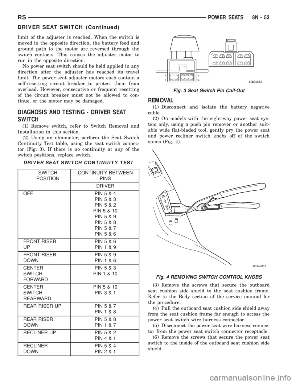
(2) Using an ohmmeter, perform the Seat Switch
Continuity Test table, using the seat switch connec-
tor (Fig. 3). If there is no continuity at any of the
switch positions, replace switch.
DRIVER SEAT SWITCH CONTINUITY TEST
SWITCH
POSITIONCONTINUITY BETWEEN
PINS
DRIVER
OFF PIN5&4
PIN5&3
PIN5&2
PIN5&10
PIN5&9
PIN5&8
PIN5&7
PIN5&6
FRONT RISER
UPPIN5&6
PIN1&9
FRONT RISER
DOWNPIN5&9
PIN1&6
CENTER
SWITCH
FORWARDPIN5&3
PIN1&10
CENTER
SWITCH
REARWARDPIN5&10
PIN3&1
REAR RISER UP PIN5&7
PIN1&8
REAR RISER
DOWNPIN5&8
PIN1&7
RECLINER UP PIN5&2
PIN4&1
RECLINER
DOWNPIN5&4
PIN2&1
REMOVAL
(1) Disconnect and isolate the battery negative
cable.
(2) On models with the eight-way power seat sys-
tem only, using a push pin remover or another suit-
able wide flat-bladed tool, gently pry the power seat
and power recliner switch knobs off of the switch
stems (Fig. 4).
(3) Remove the screws that secure the outboard
seat cushion side shield to the seat cushion frame.
Refer to the Body section of the service manual for
the procedure.
(4) Pull the outboard seat cushion side shield away
from the seat cushion frame far enough to access the
power seat switch wire harness connector.
(5) Disconnect the power seat wire harness connec-
tor from the power seat switch connector receptacle.
(6) Remove the screws that secure the power seat
switch to the inside of the outboard seat cushion side
shield.
Fig. 3 Seat Switch Pin Call-Out
Fig. 4 REMOVING SWITCH CONTROL KNOBS
RSPOWER SEATS8N-53
DRIVER SEAT SWITCH (Continued)
Page 2041 of 4284
WIRING VOLTAGE TEST
The following wiring test determines whether or
not voltage is continuous through the body harness
to switch.
(1) Remove the power window switch and bezel
assembly from the driver door. (Refer to 8 - ELEC-
TRICAL/POWER WINDOWS/POWER WINDOW
SWITCH - REMOVAL).
(2) Disconnect wire connector from back of power
window switch.
(3) Switch ignition ON position.
(4) Connect the clip end of a 12 volt test light to
Pin 13 in door harness connector at the window
switch. Touch the test light probe to Pin 9 and then
to Pin 11.
²If the test light illuminates, the wiring circuit
between the battery and switch is OK.
²If the lamp does not illuminate, first check the
25 amp circuit breaker attached to the electrical dis-
tribution wiring bracket. If the circuit breaker is OK,
then check the 40 amp fuse (#28) in the Intelligent
Power Module. If both components are OK, then
check for a broken wire.
²Refer to the appropriate wiring information.
The wiring information includes wiring diagrams,
proper wire and connector repair procedures, details
of wire harness routing and retention, connector pin-
out information and location views for the various
wire harness connectors, splices and grounds.
VENT WINDOW MOTOR
DIAGNOSIS AND TESTING - VENT WINDOW
MOTOR
If the power vent window motor is receiving proper
current and ground and does not operate proceed
with motor test. Refer to the appropriate wiring
information. The wiring information includes wiring
diagrams, proper wire and connector repair proce-
dures, details of wire harness routing and retention,
connector pin-out information and location views for
the various wire harness connectors, splices and
grounds.
(1) Remove D-pillar trim panel necessary to gain
access to power vent window motor wire connector,
(Refer to 23 - BODY/INTERIOR/LEFT D-PILLAR
TRIM PANEL - REMOVAL) or (Refer to 23 - BODY/
INTERIOR/RIGHT D-PILLAR TRIM PANEL -
REMOVAL).
(2) Disconnect power vent window motor wire con-
nector from body harness.
(3) Using two jumper wires, connect one to a bat-
tery (+) source and the other to a good ground (-).
(4) Connect the Negative (-) jumper probe to one of
the motor connector terminals.(5) Momentarily touch the Positive (+) jumper
probe to the other motor connector terminal.
When positive probe is connected the motor should
rotate in one direction to either move window open or
closed. If window is all the way open or closed the
motor will grunt and the crank system will flex when
actuated in that one direction.
Reverse jumper probes at the motor connector ter-
minals and window should now move in opposite
direction. If window does not move or grunt, replace
the motor.
If window moved completely open or closed, reverse
the jumper probes and cycle window to the opposite
position to verify full operation.
If motor grunts and does not move, verify that
crank system is not binding.
REMOVAL
(1) Disconnect and isolate the battery negative
cable.
(2) Remove D-pillar trim panel. (Refer to 23 -
BODY/INTERIOR/LEFT D-PILLAR TRIM PANEL -
REMOVAL) or (Refer to 23 - BODY/INTERIOR/
RIGHT D-PILLAR TRIM PANEL - REMOVAL).
(3) Disconnect wire connector from power vent
motor.
(4) Using a flat bladed tool, carefully lift the circu-
lar actuator link tab. Remove link from window ball
socket.
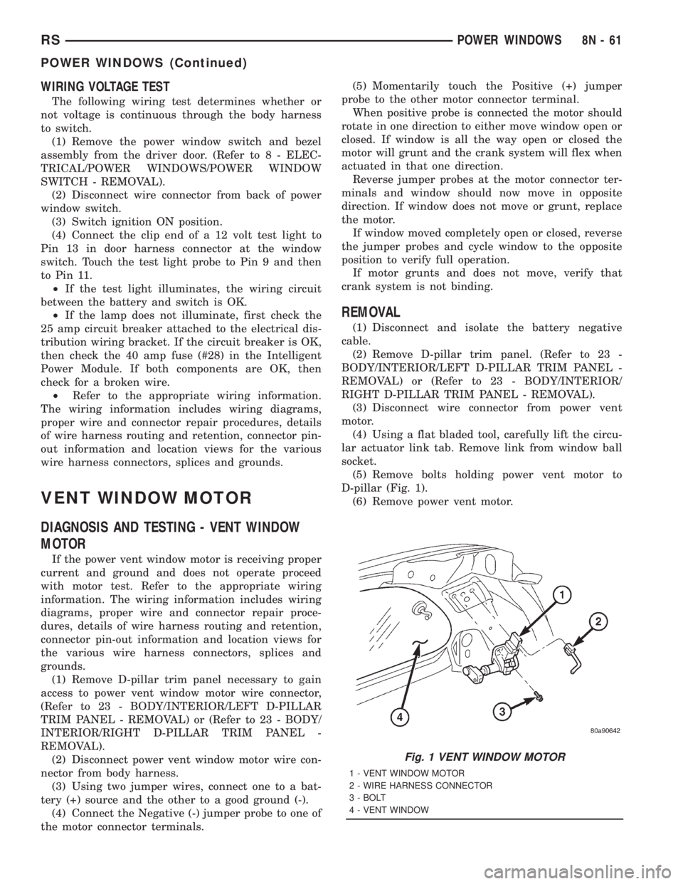
(5) Remove bolts holding power vent motor to
D-pillar (Fig. 1).
(6) Remove power vent motor.
Fig. 1 VENT WINDOW MOTOR
1 - VENT WINDOW MOTOR
2 - WIRE HARNESS CONNECTOR
3 - BOLT
4 - VENT WINDOW
RSPOWER WINDOWS8N-61
POWER WINDOWS (Continued)