ESP CHRYSLER VOYAGER 2002 User Guide
[x] Cancel search | Manufacturer: CHRYSLER, Model Year: 2002, Model line: VOYAGER, Model: CHRYSLER VOYAGER 2002Pages: 2399, PDF Size: 57.96 MB
Page 364 of 2399

(BCM), and the DRB IIItscan tool. The SKIM trans-
mits and receives RF signals through a tuned
antenna enclosed within a molded plastic ring forma-
tion that is integral to the SKIM housing. When the
SKIM is properly installed on the steering column,
the antenna ring fits snugly around the circumfer-
ence of the ignition lock cylinder housing. If this ring
is not mounted properly, communication problems
may arise in the form of transponder-related faults.
For added system security, each SKIM is pro-
grammed with a unique9Secret Key9code. This code
is stored in memory and is sent over the PCI bus to
the PCM and to each key that is programmed to
work with the vehicle. The9Secret Key9code is there-
fore a common element found in all components of
the Sentry Key Immobilizer System (SKIS). In the
event that a SKIM replacement is required, the
9Secret Key9code can be restored from the PCM by
following the SKIM replacement procedure found in
the DRB IIItscan tool. Proper completion of this
task will allow the existing ignition keys to be repro-
grammed. Therefore, new keys will NOT be needed.
In the event that the original9Secret Key9code can
not be recovered, new ignition keys will be required.
The DRB IIItscan tool will alert the technician if
key replacement is necessary. Another security code,
called a PIN, is used to gain secured access to the
SKIM for service. The SKIM also stores in its mem-
ory the Vehicle Identification Number (VIN), which it
learns through a bus message from the assembly
plant tester. The SKIS scrambles the information
that is communicated between its components in
order to reduce the possibility of unauthorized SKIM
access and/or disabling.
OPERATION
When the ignition switch is moved to the RUN
position, the SKIM transmits an RF signal to the
transponder in the ignition key. The SKIM then
waits for a response RF signal from the transponder
in the key. If the response received identifies the key
as valid, the SKIM sends a9valid key9message to
the PCM over the PCI bus. If the response received
identifies the key as invalid or no response is
received from the transponder in the ignition key, the
SKIM sends an9invalid key9message to the PCM.
The PCM will enable or disable engine operation
based upon the status of the SKIM messages. It is
important to note that the default condition in the
PCM is9invalid key.9Therefore, if no response is
received by the PCM, the engine will be immobilized
after two (2) seconds of running.The SKIM also sends indicator light status mes-
sages to the BCM to operate the light. This is the
method used to turn the light ON solid or to flash it
after the indicator light test is complete to signify a
fault in the SKIS. If the light comes ON and stays
ON solid after the indicator light test, this signifies
that the SKIM has detected a system malfunction
and/or that the SKIS has become inoperative. If the
SKIM detects an invalid keyORa key-related fault
exists, the indicator light will flash following the
indicator light test. The SKIM may also request an
audible chime if the customer key programming fea-
ture is available and the procedure is being utilized
(Refer to 8 - ELECTRICAL/VEHICLE THEFT SECU-
RITY/TRANSPONDER KEY - STANDARD PROCE-
DURE).
REMOVAL
(1)Disconnect and isolate the battery negative cable.
(2) Remove Lower Instrument Panel Cover. Refer
to Body, Instrument Panel, Lower Instrument Panel
Cover, Removal.
(3) Remove the steering column upper and lower
shrouds. Refer to Steering, Column, Column Shroud,
Removal.
(4) Disengage the steering column wire harness
from the Sentry Key Immobilizer Module (SKIM).
(5) Remove the one screws securing the SKIM to
the steering column.
(6) Rotate the SKIM upwards and then to the side
away from the steering column to slide the SKIM
antenna ring from around the ignition switch lock
cylinder housing.
(7) Remove the SKIM from the vehicle.
INSTALLATION
(1) Slip the SKIM antenna ring around the igni-
tion switch lock cylinder housing. Rotate the SKIM
downwards and then towards the steering column.
(2) Install the one screws securing the SKIM to
the steering column.
(3) Engage the steering column wire harness from
the Sentry Key Immobilizer Module (SKIM).
(4) Install the steering column upper and lower
shrouds. Refer to Steering, Column, Column Shroud,
Installation.
(5) Install the Lower Instrument Panel Cover.
Refer to Body, Instrument Panel, Lower Instrument
Panel Cover, Installation.
(6) Connect the battery negative cable.
RSELECTRONIC CONTROL MODULES8E-27
SENTRY KEY IMMOBILIZER MODULE (Continued)
ProCarManuals.com
Page 365 of 2399

TRANSMISSION CONTROL
MODULE
DESCRIPTION
The Transmission Control Module (TCM) is located
behind the left fender and is fastened with three
screws to three clips in the left frame rail forward of
the suspension (Fig. 14).
OPERATION
The TCM is the controlling unit for all electronic
operations of the transaxle. The TCM receives infor-
mation regarding vehicle operation from both direct
and indirect inputs, and selects the operational mode
of the transaxle. Direct inputs are hardwired to, and
used specifically by the TCM. Indirect inputs origi-
nate from other components/modules, and are shared
with the TCM via the J1850 communication bus.Some examples ofdirect inputsto the TCM are:
²Battery (B+) voltage
²Ignition ªONº voltage
²Transmission Control Relay (Switched B+)
²Throttle Position Sensor
²Crankshaft Position Sensor (CKP)
²Transmission Range Sensor (TRS)
²Pressure Switches (L/R, 2/4, OD)
²Transmission Temperature Sensor (Integral to
TRS)
²Input Shaft Speed Sensor
²Output Shaft Speed Sensor
Some examples ofindirect inputsto the TCM are:
²Engine/Body Identification
²Manifold Pressure
²Target Idle
²Torque Reduction Confirmation
²Speed Control ON/OFF Switch
²Engine Coolant Temperature
²Ambient/Battery Temperature
²Brake Switch Status
²DRB Communication
Based on the information received from these var-
ious inputs, the TCM determines the appropriate
shift schedule and shift points, depending on the
present operating conditions and driver demand.
This is possible through the control of various direct
and indirect outputs.
Some examples of TCMdirect outputsare:
²Transmission Control Relay
²Solenoids (LR/CC, 2/4, OD and UD)
²Vehicle Speed (to PCM)
²Torque Reduction Request (to PCM)
An example of a TCMindirect outputis:
²Transmission Temperature (to PCM)
In addition to monitoring inputs and controlling
outputs, the TCM has other important responsibili-
ties and functions:
²Storing and maintaining Clutch Volume Indices
(CVI)
²
Storing and selecting appropriate Shift Schedules
²System self-diagnostics
²Diagnostic capabilities (with DRB scan tool)
Fig. 14 Transmission Control Module (TCM)
Location
1 - TRANSMISSION CONTROL MODULE (TCM)
8E - 28 ELECTRONIC CONTROL MODULESRS
ProCarManuals.com
Page 372 of 2399
ELECTRONIC CONTROL MODULES
TABLE OF CONTENTS
page page
ENGINE CONTROL MODULE
DESCRIPTION..........................1
OPERATION............................1
STANDARD PROCEDURE - PCM/ECM/SKIM
PROGRAMMING - DIESEL...............2REMOVAL.............................4
INSTALLATION..........................4
ENGINE CONTROL MODULE
DESCRIPTION
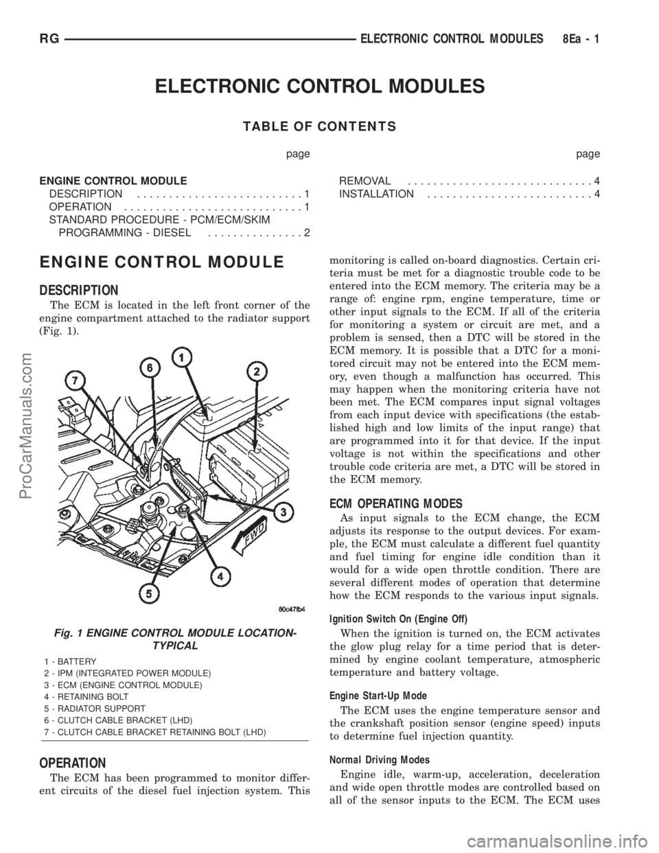
The ECM is located in the left front corner of the
engine compartment attached to the radiator support
(Fig. 1).
OPERATION
The ECM has been programmed to monitor differ-
ent circuits of the diesel fuel injection system. Thismonitoring is called on-board diagnostics. Certain cri-
teria must be met for a diagnostic trouble code to be
entered into the ECM memory. The criteria may be a
range of: engine rpm, engine temperature, time or
other input signals to the ECM. If all of the criteria
for monitoring a system or circuit are met, and a
problem is sensed, then a DTC will be stored in the
ECM memory. It is possible that a DTC for a moni-
tored circuit may not be entered into the ECM mem-
ory, even though a malfunction has occurred. This
may happen when the monitoring criteria have not
been met. The ECM compares input signal voltages
from each input device with specifications (the estab-
lished high and low limits of the input range) that
are programmed into it for that device. If the input
voltage is not within the specifications and other
trouble code criteria are met, a DTC will be stored in
the ECM memory.
ECM OPERATING MODES
As input signals to the ECM change, the ECM
adjusts its response to the output devices. For exam-
ple, the ECM must calculate a different fuel quantity
and fuel timing for engine idle condition than it
would for a wide open throttle condition. There are
several different modes of operation that determine
how the ECM responds to the various input signals.
Ignition Switch On (Engine Off)
When the ignition is turned on, the ECM activates
the glow plug relay for a time period that is deter-
mined by engine coolant temperature, atmospheric
temperature and battery voltage.
Engine Start-Up Mode
The ECM uses the engine temperature sensor and
the crankshaft position sensor (engine speed) inputs
to determine fuel injection quantity.
Normal Driving Modes
Engine idle, warm-up, acceleration, deceleration
and wide open throttle modes are controlled based on
all of the sensor inputs to the ECM. The ECM uses
Fig. 1 ENGINE CONTROL MODULE LOCATION-
TYPICAL
1 - BATTERY
2 - IPM (INTEGRATED POWER MODULE)
3 - ECM (ENGINE CONTROL MODULE)
4 - RETAINING BOLT
5 - RADIATOR SUPPORT
6 - CLUTCH CABLE BRACKET (LHD)
7 - CLUTCH CABLE BRACKET RETAINING BOLT (LHD)
RGELECTRONIC CONTROL MODULES8Ea-1
ProCarManuals.com
Page 383 of 2399
CONVENTIONAL BATTERY - GASOLINE ENGINE
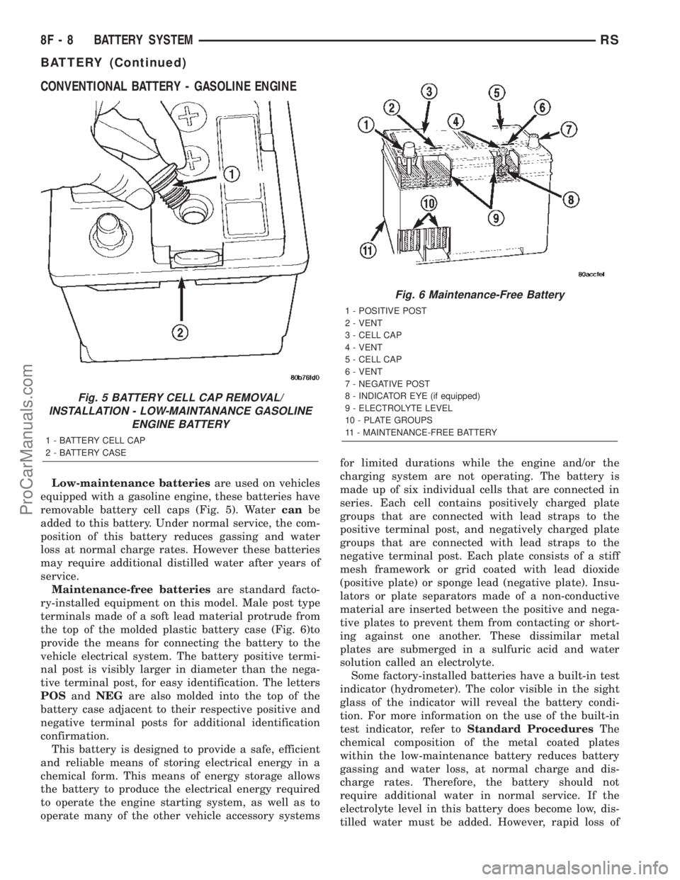
Low-maintenance batteriesare used on vehicles
equipped with a gasoline engine, these batteries have
removable battery cell caps (Fig. 5). Watercanbe
added to this battery. Under normal service, the com-
position of this battery reduces gassing and water
loss at normal charge rates. However these batteries
may require additional distilled water after years of
service.
Maintenance-free batteriesare standard facto-
ry-installed equipment on this model. Male post type
terminals made of a soft lead material protrude from
the top of the molded plastic battery case (Fig. 6)to
provide the means for connecting the battery to the
vehicle electrical system. The battery positive termi-
nal post is visibly larger in diameter than the nega-
tive terminal post, for easy identification. The letters
POSandNEGare also molded into the top of the
battery case adjacent to their respective positive and
negative terminal posts for additional identification
confirmation.
This battery is designed to provide a safe, efficient
and reliable means of storing electrical energy in a
chemical form. This means of energy storage allows
the battery to produce the electrical energy required
to operate the engine starting system, as well as to
operate many of the other vehicle accessory systemsfor limited durations while the engine and/or the
charging system are not operating. The battery is
made up of six individual cells that are connected in
series. Each cell contains positively charged plate
groups that are connected with lead straps to the
positive terminal post, and negatively charged plate
groups that are connected with lead straps to the
negative terminal post. Each plate consists of a stiff
mesh framework or grid coated with lead dioxide
(positive plate) or sponge lead (negative plate). Insu-
lators or plate separators made of a non-conductive
material are inserted between the positive and nega-
tive plates to prevent them from contacting or short-
ing against one another. These dissimilar metal
plates are submerged in a sulfuric acid and water
solution called an electrolyte.
Some factory-installed batteries have a built-in test
indicator (hydrometer). The color visible in the sight
glass of the indicator will reveal the battery condi-
tion. For more information on the use of the built-in
test indicator, refer toStandard ProceduresThe
chemical composition of the metal coated plates
within the low-maintenance battery reduces battery
gassing and water loss, at normal charge and dis-
charge rates. Therefore, the battery should not
require additional water in normal service. If the
electrolyte level in this battery does become low, dis-
tilled water must be added. However, rapid loss of
Fig. 5 BATTERY CELL CAP REMOVAL/
INSTALLATION - LOW-MAINTANANCE GASOLINE
ENGINE BATTERY
1 - BATTERY CELL CAP
2 - BATTERY CASE
Fig. 6 Maintenance-Free Battery
1 - POSITIVE POST
2 - VENT
3 - CELL CAP
4 - VENT
5 - CELL CAP
6 - VENT
7 - NEGATIVE POST
8 - INDICATOR EYE (if equipped)
9 - ELECTROLYTE LEVEL
10 - PLATE GROUPS
11 - MAINTENANCE-FREE BATTERY
8F - 8 BATTERY SYSTEMRS
BATTERY (Continued)
ProCarManuals.com
Page 419 of 2399
nal resistance and also increases the active material
surface area.
WARNING: NEVER EXCEED 14.4 VOLTS WHEN
CHARGING A SPIRAL PLATE BATTERY. PERSONAL
INJURY AND/OR BATTERY DAMAGE MAY RESULT.
Due to the maintanance-free design, distilled water
cannot be added to this battery. Therefore, if more
than 14.4 volts are used during the spiral plate bat-
tery charging process, water vapor can be exhausted
through the pressure-sensitive battery vents and lost
for good. This can permanently damage the spiral
plate battery. Never exceed 14.4 volts when charging
a spiral plate battery. Personal injury and/or battery
damage may result.
CONVENTIONAL BATTERY - GASOLINE ENGINE
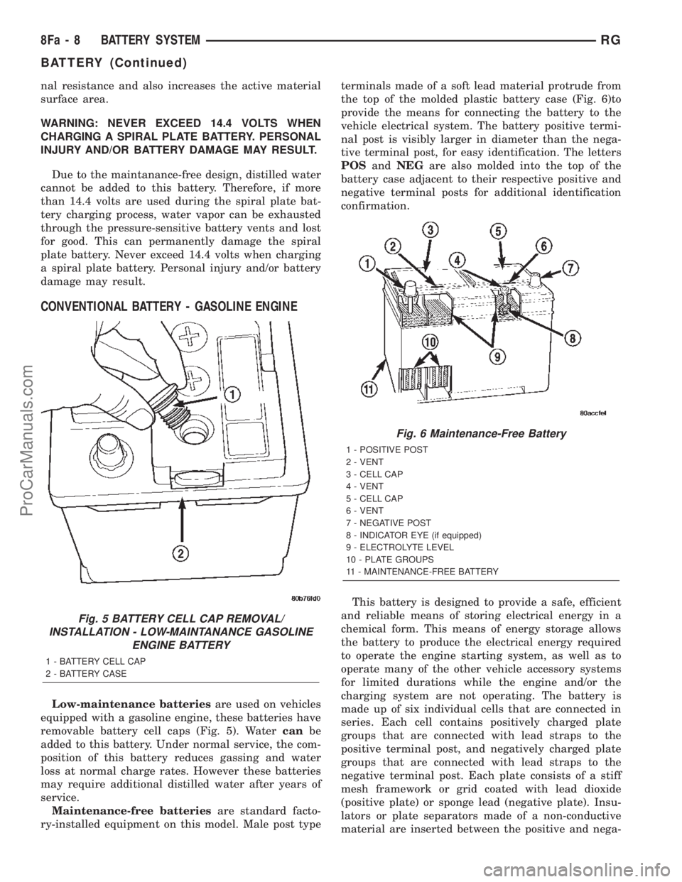
Low-maintenance batteriesare used on vehicles
equipped with a gasoline engine, these batteries have
removable battery cell caps (Fig. 5). Watercanbe
added to this battery. Under normal service, the com-
position of this battery reduces gassing and water
loss at normal charge rates. However these batteries
may require additional distilled water after years of
service.
Maintenance-free batteriesare standard facto-
ry-installed equipment on this model. Male post typeterminals made of a soft lead material protrude from
the top of the molded plastic battery case (Fig. 6)to
provide the means for connecting the battery to the
vehicle electrical system. The battery positive termi-
nal post is visibly larger in diameter than the nega-
tive terminal post, for easy identification. The letters
POSandNEGare also molded into the top of the
battery case adjacent to their respective positive and
negative terminal posts for additional identification
confirmation.
This battery is designed to provide a safe, efficient
and reliable means of storing electrical energy in a
chemical form. This means of energy storage allows
the battery to produce the electrical energy required
to operate the engine starting system, as well as to
operate many of the other vehicle accessory systems
for limited durations while the engine and/or the
charging system are not operating. The battery is
made up of six individual cells that are connected in
series. Each cell contains positively charged plate
groups that are connected with lead straps to the
positive terminal post, and negatively charged plate
groups that are connected with lead straps to the
negative terminal post. Each plate consists of a stiff
mesh framework or grid coated with lead dioxide
(positive plate) or sponge lead (negative plate). Insu-
lators or plate separators made of a non-conductive
material are inserted between the positive and nega-
Fig. 5 BATTERY CELL CAP REMOVAL/
INSTALLATION - LOW-MAINTANANCE GASOLINE
ENGINE BATTERY
1 - BATTERY CELL CAP
2 - BATTERY CASE
Fig. 6 Maintenance-Free Battery
1 - POSITIVE POST
2 - VENT
3 - CELL CAP
4 - VENT
5 - CELL CAP
6 - VENT
7 - NEGATIVE POST
8 - INDICATOR EYE (if equipped)
9 - ELECTROLYTE LEVEL
10 - PLATE GROUPS
11 - MAINTENANCE-FREE BATTERY
8Fa - 8 BATTERY SYSTEMRG
BATTERY (Continued)
ProCarManuals.com
Page 462 of 2399
DRIVER HEATED SEAT
SWITCH
DESCRIPTION
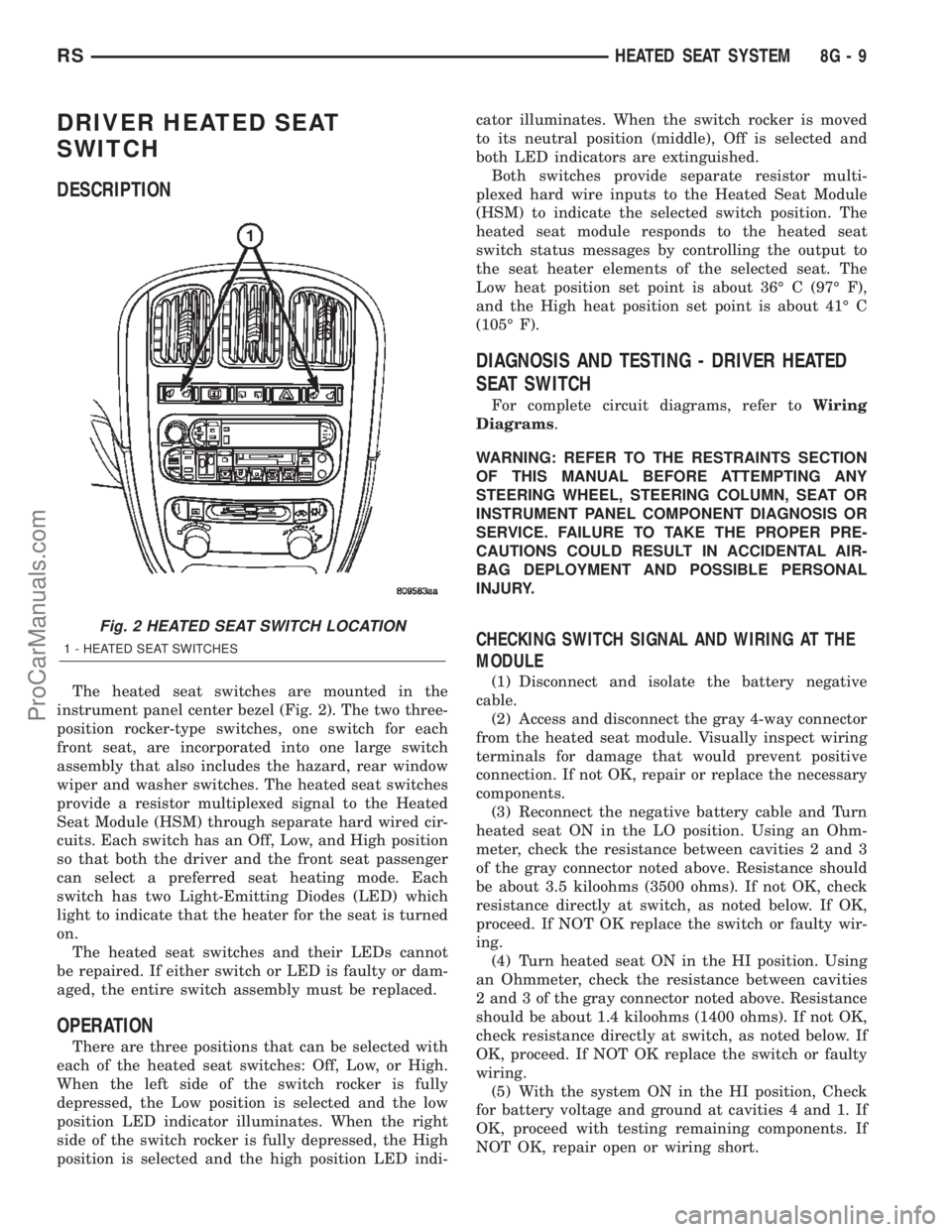
The heated seat switches are mounted in the
instrument panel center bezel (Fig. 2). The two three-
position rocker-type switches, one switch for each
front seat, are incorporated into one large switch
assembly that also includes the hazard, rear window
wiper and washer switches. The heated seat switches
provide a resistor multiplexed signal to the Heated
Seat Module (HSM) through separate hard wired cir-
cuits. Each switch has an Off, Low, and High position
so that both the driver and the front seat passenger
can select a preferred seat heating mode. Each
switch has two Light-Emitting Diodes (LED) which
light to indicate that the heater for the seat is turned
on.
The heated seat switches and their LEDs cannot
be repaired. If either switch or LED is faulty or dam-
aged, the entire switch assembly must be replaced.
OPERATION
There are three positions that can be selected with
each of the heated seat switches: Off, Low, or High.
When the left side of the switch rocker is fully
depressed, the Low position is selected and the low
position LED indicator illuminates. When the right
side of the switch rocker is fully depressed, the High
position is selected and the high position LED indi-cator illuminates. When the switch rocker is moved
to its neutral position (middle), Off is selected and
both LED indicators are extinguished.
Both switches provide separate resistor multi-
plexed hard wire inputs to the Heated Seat Module
(HSM) to indicate the selected switch position. The
heated seat module responds to the heated seat
switch status messages by controlling the output to
the seat heater elements of the selected seat. The
Low heat position set point is about 36É C (97É F),
and the High heat position set point is about 41É C
(105É F).
DIAGNOSIS AND TESTING - DRIVER HEATED
SEAT SWITCH
For complete circuit diagrams, refer toWiring
Diagrams.
WARNING: REFER TO THE RESTRAINTS SECTION
OF THIS MANUAL BEFORE ATTEMPTING ANY
STEERING WHEEL, STEERING COLUMN, SEAT OR
INSTRUMENT PANEL COMPONENT DIAGNOSIS OR
SERVICE. FAILURE TO TAKE THE PROPER PRE-
CAUTIONS COULD RESULT IN ACCIDENTAL AIR-
BAG DEPLOYMENT AND POSSIBLE PERSONAL
INJURY.
CHECKING SWITCH SIGNAL AND WIRING AT THE
MODULE
(1) Disconnect and isolate the battery negative
cable.
(2) Access and disconnect the gray 4-way connector
from the heated seat module. Visually inspect wiring
terminals for damage that would prevent positive
connection. If not OK, repair or replace the necessary
components.
(3) Reconnect the negative battery cable and Turn
heated seat ON in the LO position. Using an Ohm-
meter, check the resistance between cavities 2 and 3
of the gray connector noted above. Resistance should
be about 3.5 kiloohms (3500 ohms). If not OK, check
resistance directly at switch, as noted below. If OK,
proceed. If NOT OK replace the switch or faulty wir-
ing.
(4) Turn heated seat ON in the HI position. Using
an Ohmmeter, check the resistance between cavities
2 and 3 of the gray connector noted above. Resistance
should be about 1.4 kiloohms (1400 ohms). If not OK,
check resistance directly at switch, as noted below. If
OK, proceed. If NOT OK replace the switch or faulty
wiring.
(5) With the system ON in the HI position, Check
for battery voltage and ground at cavities 4 and 1. If
OK, proceed with testing remaining components. If
NOT OK, repair open or wiring short.
Fig. 2 HEATED SEAT SWITCH LOCATION
1 - HEATED SEAT SWITCHES
RSHEATED SEAT SYSTEM8G-9
ProCarManuals.com
Page 466 of 2399

PASSENGER HEATED SEAT
SWITCH
DESCRIPTION
The heated seat switches are mounted in the
instrument panel center bezel (Fig. 6). The two three-
position rocker-type switches, one switch for each
front seat, are incorporated into one large switch
assembly that also includes the hazard, rear window
wiper and washer switches. The heated seat switches
provide a resistor multiplexed signal to the Heated
Seat Module (HSM) through separate hard wired cir-
cuits. Each switch has an Off, Low, and High position
so that both the driver and the front seat passenger
can select a preferred seat heating mode. Each
switch has two Light-Emitting Diodes (LED) which
light to indicate that the heater for the seat is turned
on.
The heated seat switches and their LEDs cannot
be repaired. If either switch or LED is faulty or dam-
aged, the entire switch assembly must be replaced.
OPERATION
There are three positions that can be selected with
each of the heated seat switches: Off, Low, or High.
When the left side of the switch rocker is fully
depressed, the Low position is selected and the low
position LED indicator illuminates. When the right
side of the switch rocker is fully depressed, the High
position is selected and the high position LED indi-cator illuminates. When the switch rocker is moved
to its neutral position (middle), Off is selected and
both LED indicators are extinguished.
Both switches provide separate resistor multi-
plexed hard wire inputs to the Heated Seat Module
(HSM) to indicate the selected switch position. The
heated seat module responds to the heated seat
switch status messages by controlling the output to
the seat heater elements of the selected seat. The
Low heat position set point is about 36É C (97É F),
and the High heat position set point is about 41É C
(105É F).
DIAGNOSIS AND TESTING - PASSENGER
HEATED SEAT SWITCH
For complete circuit diagrams, refer toWiring
Diagrams.
WARNING: REFER TO THE RESTRAINTS SECTION
OF THIS MANUAL BEFORE ATTEMPTING ANY
STEERING WHEEL, STEERING COLUMN, SEAT OR
INSTRUMENT PANEL COMPONENT DIAGNOSIS OR
SERVICE. FAILURE TO TAKE THE PROPER PRE-
CAUTIONS COULD RESULT IN ACCIDENTAL AIR-
BAG DEPLOYMENT AND POSSIBLE PERSONAL
INJURY.
CHECKING SWITCH SIGNAL AND WIRING AT THE
MODULE
(1) Disconnect and isolate the battery negative
cable.
(2) Access and disconnect the gray 4-way connector
from the heated seat module. Visually inspect wiring
terminals for damage that would prevent positive
connection. If not OK, repair or replace the necessary
components.
(3) Reconnect the negative battery cable and Turn
heated seat ON in the LO position. Using an Ohm-
meter, check the resistance between cavities 2 and 3
of the gray connector noted above. Resistance should
be about 3.5 kiloohms (3500 ohms). If not OK, check
resistance directly at switch, as noted below. If OK,
proceed. If NOT OK replace the switch or faulty wir-
ing.
(4) Turn heated seat ON in the HI position. Using
an Ohmmeter, check the resistance between cavities
2 and 3 of the gray connector noted above. Resistance
should be about 1.4 kiloohms (1400 ohms). If not OK,
check resistance directly at switch, as noted below. If
OK, proceed. If NOT OK replace the switch or faulty
wiring.
(5) With the system ON in the HI position, Check
for battery voltage and ground at cavities 4 and 1. If
OK, proceed with testing remaining components. If
NOT OK, repair open or wiring short.
Fig. 6 HEATED SEAT SWITCH LOCATION
1 - HEATED SEAT SWITCHES
RSHEATED SEAT SYSTEM8G-13
ProCarManuals.com
Page 470 of 2399
HORN
TABLE OF CONTENTS
page page
HORN SYSTEM
DESCRIPTION..........................1
OPERATION............................1
DIAGNOSIS AND TESTING - HORN SYSTEM . . . 1
HORN
DIAGNOSIS AND TESTING - HORN..........3
REMOVAL.............................4INSTALLATION..........................4
HORN RELAY
DIAGNOSIS AND TESTING - HORN RELAY....5
REMOVAL.............................5
INSTALLATION..........................5
HORN SWITCH
DESCRIPTION..........................5
HORN SYSTEM
DESCRIPTION
WARNING: ON VEHICLES EQUIPPED WITH AIR-
BAG, REFER TO ELECTRICAL, RESTRAINTS FOR
SAFETY PRECAUTIONS. DISCONNECT THE NEGA-
TIVE CABLE FROM THE BATTERY BEFORE SER-
VICING COMPONENTS INVOLVING THE AIRBAG
SYSTEM. ACCIDENTAL DEPLOYMENT OF AIRBAG
AND PERSONAL INJURY CAN RESULT.
The horn circuit consists of a horn switch, clock-
spring, horn relay, horns and Integrated Power Mod-
ule (IPM). The horn switch is a membrane switch
located in the airbag trim cover. The horns are
located forward of the left front wheel behind the
bumper fascia.
OPERATION
The horn relay plugs into the Integrated Power
Module (IPM) which is located in the engine com-
partment. For circuit information and component
locations, refer to the appropriate wiring information.
The wiring information includes wiring diagrams,
proper wire and connector repair procedures, details
of wire harness routing and retention, connector pin-
out information and location views for the various
wire harness connectors, splices and grounds.
The horns will not function if the switch is
ªCLOSEDº for more than 30 seconds. Once the
switch is ªOPENº, a 20±30 second delay will occur
before the horns are functional again.
DIAGNOSIS AND TESTING - HORN SYSTEM
WARNING: ON VEHICLES EQUIPPED WITH AIR-
BAGS, REFER TO ELECTRICAL, RESTRAINTS
BEFORE ATTEMPTING ANY STEERING WHEEL,
STEERING COLUMN, OR INSTRUMENT PANEL
COMPONENT DIAGNOSIS OR SERVICE. FAILURE
TO TAKE THE PROPER PRECAUTIONS COULD
RESULT IN ACCIDENTAL AIRBAG DEPLOYMENT
AND POSSIBLE PERSONAL INJURY.
Refer to Horn System Test below. If the horn does
not sound, check horn fuse located in the Integrated
Power Module (IPM). If the fuse is blown, replace
with the correct fuse. If the horns fail to sound and
the new fuse blows when depressing the horn switch,
a short circuit in the horn or the horn wiring
between the fuse terminal and the horn is responsi-
ble, or a defective horn switch allowed the horn to
burn out is responsible.
If the fuse is OK, test horn relay (Refer to 8 -
ELECTRICAL/HORN/HORN RELAY - DIAGNOSIS
AND TESTING).
If the relay is OK, test horn. Refer to Horn System
Test.
CAUTION: Continuous sounding of horn may
cause horn failure.
Should the horn sound continuously:
²Unplug the horn relay from IPM.
²Refer to (Refer to 8 - ELECTRICAL/HORN/
HORN RELAY - DIAGNOSIS AND TESTING).
Refer to the appropriate wiring information. The
wiring information includes wiring diagrams, proper
wire and connector repair procedures, details of wire
harness routing and retention, connector pin-out
information and location views for the various wire
harness connectors, splices and grounds.
RSHORN8H-1
ProCarManuals.com
Page 483 of 2399
INSTALLATION - 3.3/3.8L
(1) Install coil over studs on bracket.
(2) Install 2 bolts to ignition coil.
(3) Install 2 nuts to the ignition coil studs. Tighten
nuts and bolts.
(4) Connect the electrical connector to the ignition
coil.
(5) Install the ignition cables to the ignition coil.
(6) Reposition the Power steering reservoir. Slide
bracket over the mounting stud (Fig. 11).
(7) Install 2 bolts to the Power steering reservoir
to intake manifold.
(8) Tighten the lower nut to stud on ignition coil
bracket.
(9) Install the throttle and speed control cables to
clip.
(10) Connect the negative battery cable.
KNOCK SENSOR
DESCRIPTION
The knock sensor threads into the cylinder block.
The knock sensor is designed to detect engine vibra-
tion that is caused by detonation.
OPERATION
When the knock sensor detects a knock in one of
the cylinders, it sends an input signal to the PCM. In
response, the PCM retards ignition timing for all cyl-
inders by a scheduled amount.
Knock sensors contain a piezoelectric material
which constantly vibrates and sends an input voltage
(signal) to the PCM while the engine operates. As the
intensity of the crystal's vibration increases, the
knock sensor output voltage also increases.
The voltage signal produced by the knock sensor
increases with the amplitude of vibration. The PCM
receives as an input the knock sensor voltage signal.
If the signal rises above a predetermined level, the
PCM will store that value in memory and retard
ignition timing to reduce engine knock. If the knock
sensor voltage exceeds a preset value, the PCM
retards ignition timing for all cylinders. It is not a
selective cylinder retard.
The PCM ignores knock sensor input during engine
idle conditions. Once the engine speed exceeds a
specified value, knock retard is allowed.
Knock retard uses its own short term and long
term memory program.
Long term memory stores previous detonation
information in its battery-backed RAM. The maxi-
mum authority that long term memory has over tim-
ing retard can be calibrated.
Short term memory is allowed to retard timing up
to a preset amount under all operating conditions (aslong as rpm is above the minimum rpm) except WOT.
The PCM, using short term memory, can respond
quickly to retard timing when engine knock is
detected. Short term memory is lost any time the
ignition key is turned off.
NOTE: Over or under tightening affects knock sen-
sor performance, possibly causing improper spark
control.
REMOVAL
REMOVAL - 2.4L
The knock sensor threads into the side of the cyl-
inder block in front of the starter (Fig. 12).
(1) Disconnect electrical connector from knock sen-
sor.
(2) Use a crow foot socket to remove the knock
sensors.
REMOVAL - 3.8L
The knock sensor threads into the side of the cyl-
inder block in the rear.
(1) Disconnect the negative battery cable.
(2) Raise vehicle and support.
(3) On All Wheel Drive vehicles remove the PTU
(Power Transfer Unit), refer to the Transmission sec-
tion for more information.
(4) Disconnect electrical connector from knock sen-
sor.
(5) Use a crow foot socket to remove the knock
sensor.
INSTALLATION
INSTALLATION - 2.4L
The knock sensor threads into the side of the cyl-
inder block in front of the starter (Fig. 12).
(1) Install knock sensor. Tighten knock sensor to
10 N´m (7 ft. lbs.) torque.Over or under tighten-
ing effects knock sensor performance, possibly
causing improper spark control.
(2) Attach electrical connector to knock sensor.
INSTALLATION - 3.8L
The knock sensor threads into the side of the cyl-
inder block in the rear.
(1) Install knock sensor. Tighten knock sensor to
10 N´m (7 ft. lbs.) torque.Over or under tighten-
ing effects knock sensor performance, possibly
causing improper spark control.
(2) Attach electrical connector to knock sensor.
8I - 8 IGNITION CONTROLRS
IGNITION COIL (Continued)
ProCarManuals.com
Page 490 of 2399

NOTE: Always check the functionality of the cluster
by running the self test prior to troubleshooting.
INSTRUMENT CLUSTER DIAGNOSIS
CONDITION POSSIBLE CAUSES CORRECTION
INSTRUMENT CLUSTER
INOPERATIVE. NO
RESPONSE FROM
INSTRUMENT CLUSTER.NO PCI BUS MESSAGES
FROM THE BCM.USE A DRB IIITSCAN TOOL TO CHECK THE BCM.
IF OK, LOOK FOR ANOTHER POSSIBLE CAUSE
FOR CLUSTER FAILURE. IF NOT OK, REFER TO
THE PROPER BODY DIAGNOSTIC PROCEDURES
MANUAL.
SPREAD TERMINAL(S)
ON WIRING HARNESS
CLUSTER CONNECTOR.REMOVE CLUSTER FROM INSTRUMENT PANEL
AND CHECK WIRING HARNESS CONNECTOR FOR
SPREAD TERMINAL. IF OK, LOOK FOR ANOTHER
POSSIBLE CAUSE FOR THE CLUSTER FAILURE. IF
NOT OK, REPAIR CONNECTOR.
BCM IS NOT RECEIVING
PROPER INPUT FROM
THE IGNITION SWITCH.1. USE A DRB IIITSCAN TOOL TO VERIFY IGNITION
SWITCH STATUS INTO THE BCM. IF NOT OK, GO
TO STEP (2). IF OK, LOOK AT ANOTHER POSSIBLE
CAUSE OF FAILURE.
2. CHECK IGNITION SWITCH FUNCTION AND
WIRING.
INTERNAL CLUSTER
FAILURE.REPLACE CLUSTER.
WAKE UP CIRCUIT
FAULTY.VERIFY CONTINUITY OF WAKE UP CIRCUIT FROM
BCM TO MIC. CIRCUIT SHALL BE LOW WHENEVER
BCM IS AWAKE.
POWER OR GROUND
MISSING.IF NO RESPONSE FROM THE MIC, CHECK FOR
POWER AND GROUND AT THE MIC CONNECTOR.
REFER TO WIRING DIAGRAMS FOR CONNECTOR
CALL OUTS.
RSINSTRUMENT CLUSTER8J-3
INSTRUMENT CLUSTER (Continued)
ProCarManuals.com