audio CHRYSLER VOYAGER 2002 User Guide
[x] Cancel search | Manufacturer: CHRYSLER, Model Year: 2002, Model line: VOYAGER, Model: CHRYSLER VOYAGER 2002Pages: 2399, PDF Size: 57.96 MB
Page 329 of 2399
(9) Disconnect the wire connectors from the back
of the radio.
INSTALLATION
(1) Connect wire harness to back of radio.
(2) Install bolt holding ground strap to the radio (if
equipped).
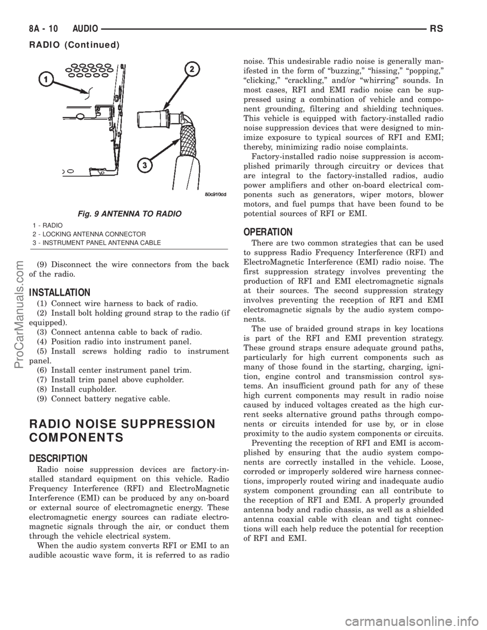
(3) Connect antenna cable to back of radio.
(4) Position radio into instrument panel.
(5) Install screws holding radio to instrument
panel.
(6) Install center instrument panel trim.
(7) Install trim panel above cupholder.
(8) Install cupholder.
(9) Connect battery negative cable.
RADIO NOISE SUPPRESSION
COMPONENTS
DESCRIPTION
Radio noise suppression devices are factory-in-
stalled standard equipment on this vehicle. Radio
Frequency Interference (RFI) and ElectroMagnetic
Interference (EMI) can be produced by any on-board
or external source of electromagnetic energy. These
electromagnetic energy sources can radiate electro-
magnetic signals through the air, or conduct them
through the vehicle electrical system.
When the audio system converts RFI or EMI to an
audible acoustic wave form, it is referred to as radionoise. This undesirable radio noise is generally man-
ifested in the form of ªbuzzing,º ªhissing,º ªpopping,º
ªclicking,º ªcrackling,º and/or ªwhirringº sounds. In
most cases, RFI and EMI radio noise can be sup-
pressed using a combination of vehicle and compo-
nent grounding, filtering and shielding techniques.
This vehicle is equipped with factory-installed radio
noise suppression devices that were designed to min-
imize exposure to typical sources of RFI and EMI;
thereby, minimizing radio noise complaints.
Factory-installed radio noise suppression is accom-
plished primarily through circuitry or devices that
are integral to the factory-installed radios, audio
power amplifiers and other on-board electrical com-
ponents such as generators, wiper motors, blower
motors, and fuel pumps that have been found to be
potential sources of RFI or EMI.
OPERATION
There are two common strategies that can be used
to suppress Radio Frequency Interference (RFI) and
ElectroMagnetic Interference (EMI) radio noise. The
first suppression strategy involves preventing the
production of RFI and EMI electromagnetic signals
at their sources. The second suppression strategy
involves preventing the reception of RFI and EMI
electromagnetic signals by the audio system compo-
nents.
The use of braided ground straps in key locations
is part of the RFI and EMI prevention strategy.
These ground straps ensure adequate ground paths,
particularly for high current components such as
many of those found in the starting, charging, igni-
tion, engine control and transmission control sys-
tems. An insufficient ground path for any of these
high current components may result in radio noise
caused by induced voltages created as the high cur-
rent seeks alternative ground paths through compo-
nents or circuits intended for use by, or in close
proximity to the audio system components or circuits.
Preventing the reception of RFI and EMI is accom-
plished by ensuring that the audio system compo-
nents are correctly installed in the vehicle. Loose,
corroded or improperly soldered wire harness connec-
tions, improperly routed wiring and inadequate audio
system component grounding can all contribute to
the reception of RFI and EMI. A properly grounded
antenna body and radio chassis, as well as a shielded
antenna coaxial cable with clean and tight connec-
tions will each help reduce the potential for reception
of RFI and EMI.
Fig. 9 ANTENNA TO RADIO
1 - RADIO
2 - LOCKING ANTENNA CONNECTOR
3 - INSTRUMENT PANEL ANTENNA CABLE
8A - 10 AUDIORS
RADIO (Continued)
ProCarManuals.com
Page 330 of 2399
REMOTE SWITCHES
DESCRIPTION
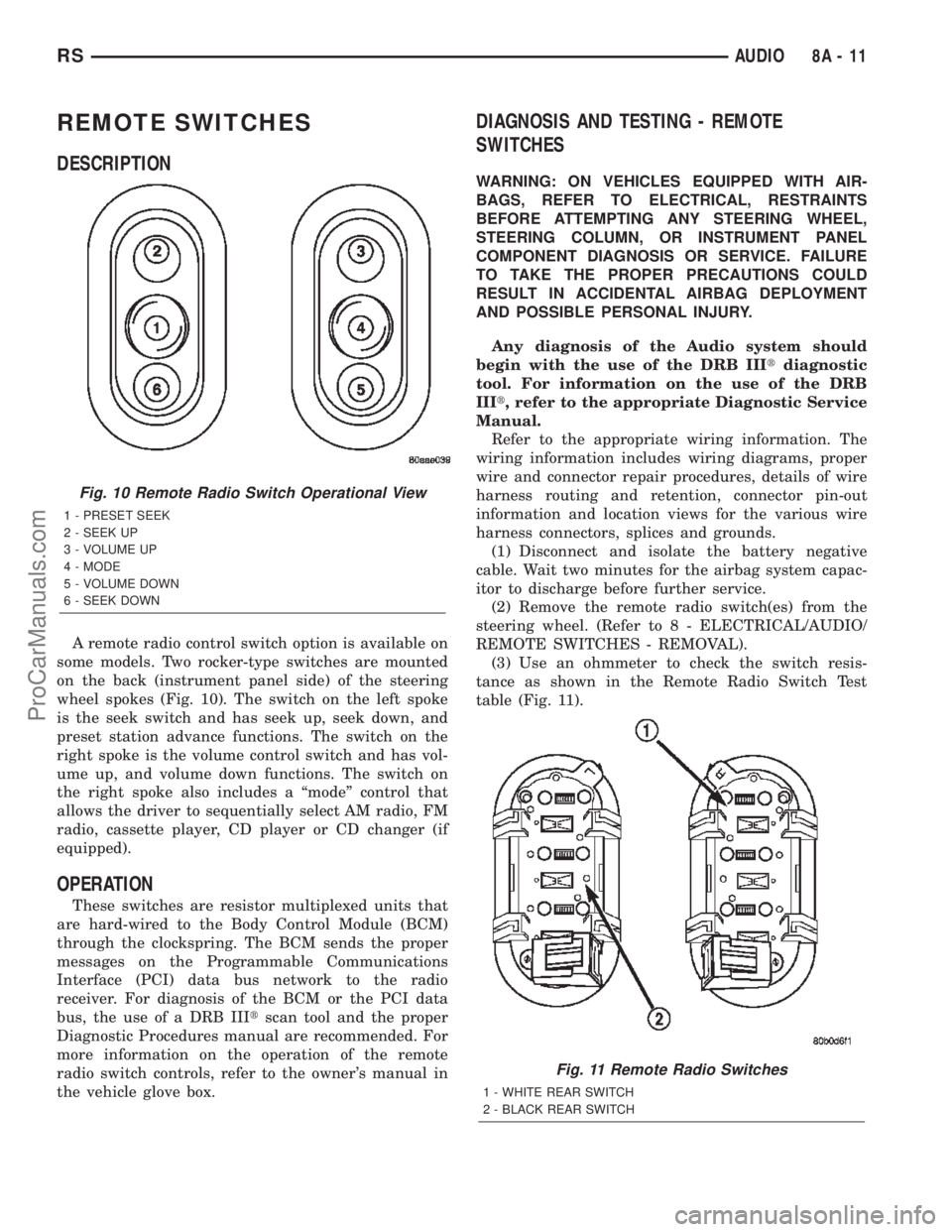
A remote radio control switch option is available on
some models. Two rocker-type switches are mounted
on the back (instrument panel side) of the steering
wheel spokes (Fig. 10). The switch on the left spoke
is the seek switch and has seek up, seek down, and
preset station advance functions. The switch on the
right spoke is the volume control switch and has vol-
ume up, and volume down functions. The switch on
the right spoke also includes a ªmodeº control that
allows the driver to sequentially select AM radio, FM
radio, cassette player, CD player or CD changer (if
equipped).
OPERATION
These switches are resistor multiplexed units that
are hard-wired to the Body Control Module (BCM)
through the clockspring. The BCM sends the proper
messages on the Programmable Communications
Interface (PCI) data bus network to the radio
receiver. For diagnosis of the BCM or the PCI data
bus, the use of a DRB IIItscan tool and the proper
Diagnostic Procedures manual are recommended. For
more information on the operation of the remote
radio switch controls, refer to the owner's manual in
the vehicle glove box.
DIAGNOSIS AND TESTING - REMOTE
SWITCHES
WARNING: ON VEHICLES EQUIPPED WITH AIR-
BAGS, REFER TO ELECTRICAL, RESTRAINTS
BEFORE ATTEMPTING ANY STEERING WHEEL,
STEERING COLUMN, OR INSTRUMENT PANEL
COMPONENT DIAGNOSIS OR SERVICE. FAILURE
TO TAKE THE PROPER PRECAUTIONS COULD
RESULT IN ACCIDENTAL AIRBAG DEPLOYMENT
AND POSSIBLE PERSONAL INJURY.
Any diagnosis of the Audio system should
begin with the use of the DRB IIItdiagnostic
tool. For information on the use of the DRB
IIIt, refer to the appropriate Diagnostic Service
Manual.
Refer to the appropriate wiring information. The
wiring information includes wiring diagrams, proper
wire and connector repair procedures, details of wire
harness routing and retention, connector pin-out
information and location views for the various wire
harness connectors, splices and grounds.
(1) Disconnect and isolate the battery negative
cable. Wait two minutes for the airbag system capac-
itor to discharge before further service.
(2) Remove the remote radio switch(es) from the
steering wheel. (Refer to 8 - ELECTRICAL/AUDIO/
REMOTE SWITCHES - REMOVAL).
(3) Use an ohmmeter to check the switch resis-
tance as shown in the Remote Radio Switch Test
table (Fig. 11).
Fig. 10 Remote Radio Switch Operational View
1 - PRESET SEEK
2 - SEEK UP
3 - VOLUME UP
4 - MODE
5 - VOLUME DOWN
6 - SEEK DOWN
Fig. 11 Remote Radio Switches
1 - WHITE REAR SWITCH
2 - BLACK REAR SWITCH
RSAUDIO8A-11
ProCarManuals.com
Page 331 of 2399

REMOTE RADIO SWITCH TEST
SWITCH POSITION RESISTANCE
VOLUME UP 7320 OHMS
VOLUME DOWN 1210 OHMS
SEEK UP 4530 OHMS
SEEK DOWN 2050 OHMS
PRE-SET STATION ADVANCE 10 OHMS
NOTE: The right remote radio switch back is white
in color. The left switch back is black in color. The
right/left remote radio switch orientation is with the
steering wheel installed, and driver in drivers seat.
(4) If the switch resistance checks OK, go to Step
5. If not OK, replace the faulty switch.
(5) Check for continuity between the ground cir-
cuit cavity of the switch wire harness connector and
a good ground. There should be continuity. If OK, go
to Step 6. If not OK, repair the open circuit as
required.
(6) Unplug the 24-way white wire harness connec-
tor from the Body Control Module (BCM). Check for
continuity between the radio control circuit cavity of
the remote radio switch wire harness connector and a
good ground. There should be no continuity. If OK, go
to Step 7. If not OK, repair the short circuit as
required.
(7) Check for continuity between the radio control
circuit cavities of the remote radio switch wire har-
ness connector and the BCM wire harness connector.
There should be continuity. If OK, refer to the proper
Diagnostic Procedures manual to test the BCM and
the PCI data bus. If not OK, repair the open circuit
as required.
REMOVAL
WARNING: ON VEHICLES EQUIPPED WITH AIR-
BAGS, REFER TO ELECTRICAL, RESTRAINTS
BEFORE ATTEMPTING ANY STEERING WHEEL,
STEERING COLUMN, OR INSTRUMENT PANEL
COMPONENT DIAGNOSIS OR SERVICE. FAILURE
TO TAKE THE PROPER PRECAUTIONS COULD
RESULT IN ACCIDENTAL AIRBAG DEPLOYMENT
AND POSSIBLE PERSONAL INJURY.
(1) Disconnect and isolate the battery negative
cable. Wait two minutes for the airbag system capac-
itor to discharge before further service.
(2) Remove the driver side airbag module from the
vehicle. Refer to ELECTRICAL/RESTRAINTS/
DRIVER AIR BAG.(3) Remove the steering wheel from the steering
column. Refer to STEERING/COLUMN/STEERING
WHEEL.
(4) Unplug the wire harness connector from the
remote radio switch (s).
(5) Remove three screws securing steering wheel
rear cover.
(6) Remove the remote radio switch from the steer-
ing wheel by depressing tabs on each side of each
switch.
NOTE: The right remote radio switch back is white
in color. The left switch back is black in color. The
right/left remote radio switch orientation is with the
steering wheel installed, and driver in drivers seat.
INSTALLATION
WARNING: ON VEHICLES EQUIPPED WITH AIR-
BAGS, REFER TO ELECTRICAL, RESTRAINTS
BEFORE ATTEMPTING ANY STEERING WHEEL,
STEERING COLUMN, OR INSTRUMENT PANEL
COMPONENT DIAGNOSIS OR SERVICE. FAILURE
TO TAKE THE PROPER PRECAUTIONS COULD
RESULT IN ACCIDENTAL AIRBAG DEPLOYMENT
AND POSSIBLE PERSONAL INJURY.
(1)
Install remote radio switch to the steering wheel.
(2) Install three screws securing steering wheel
rear cover.
(3) Connect the wire harness to the remote radio
switch.
(4) Install the steering wheel. Refer to STEERING/
COLUMN/STEERING WHEEL.
(5) Install the driver side airbag module. Refer to
ELECTRICAL/RESTRAINTS/DRIVER AIRBAG.
(6) Connect the battery negative cable.
SPEAKER
DIAGNOSIS AND TESTING - SPEAKER
WARNING: DISABLE THE AIRBAG SYSTEM BEFORE
ATTEMPTING ANY STEERING WHEEL, STEERING
COLUMN, SEAT BELT TENSIONER, SIDE AIRBAG,
OR INSTRUMENT PANEL COMPONENT DIAGNOSIS
OR SERVICE. DISCONNECT AND ISOLATE THE BAT-
TERY NEGATIVE (GROUND) CABLE, THEN WAIT
TWO MINUTES FOR THE AIRBAG SYSTEM CAPACI-
TOR TO DISCHARGE BEFORE PERFORMING FUR-
THER DIAGNOSIS OR SERVICE. THIS IS THE ONLY
SURE WAY TO DISABLE THE AIRBAG SYSTEM.
FAILURE TO TAKE THE PROPER PRECAUTIONS
COULD RESULT IN ACCIDENTAL AIRBAG DEPLOY-
MENT AND POSSIBLE PERSONAL INJURY.
8A - 12 AUDIORS
REMOTE SWITCHES (Continued)
ProCarManuals.com
Page 332 of 2399
Any diagnosis of the Audio system should
begin with the use of the DRB IIItdiagnostic
tool. For information on the use of the DRB
IIIt, refer to the appropriate Diagnostic Service
Manual.
Refer to the appropriate wiring information. The
wiring information includes wiring diagrams, proper
wire and connector repair procedures, details of wire
harness routing and retention, connector pin-out
information and location views for the various wire
harness connectors, splices and grounds.
CAUTION: The speaker output of the radio is a
ªfloating groundº system. Do not allow any speaker
lead to short to ground, as damage to the radio
may result.
(1) If all speakers are inoperative, check the radio
fuses in the junction block. If OK, go to Step 2. If not
OK, repair the shorted circuit or component as
required and replace the faulty fuse.
(2) Turn the ignition switch to the ON position.
Turn the radio receiver ON. Adjust the balance and
fader control controls to check the performance of
each individual speaker. Note the speaker locations
that are not performing correctly. Go to Step 3.
(3) Turn the radio receiver OFF. Turn the ignition
OFF. Disconnect and isolate the battery negative
cable. Remove the radio receiver.
(4) Check both the speaker feed (+) circuit and
return (-) circuit cavities for the inoperative speaker
at the radio receiver wire harness connector for con-
tinuity to ground. There should be no continuity. If
OK, go to Step 5. If not OK, repair the shorted
speaker feed (+) and/or return (-) circuits(s) to the
speaker as required.
(5) Disconnect wire harness connector at the inop-
erative speaker. Check for continuity between the
speaker feed (+) circuit cavities of the radio receiver
wire harness connector. Repeat the check between
the speaker return (-) circuit cavities of the radio
receiver wire harness connector and the speaker wire
harness connector. In each case, there should be con-
tinuity. If OK, replace the faulty speaker. If not OK,
repair the open speaker feed (+) and/or return (-) cir-
cuits(s) as required.
REMOVAL
D-PILLAR SPEAKER
(1)Disconnect and isolate the battery negative cable.
(2) Remove rear header trim (right side speaker).
(3) Remove jack cover (left side speaker).
(4) Remove liftgate scuff plate.
(5) Remove upper seat belt bolt. (Refer to 8 -
ELECTRICAL/RESTRAINTS/SEAT BELT OUT-
BOARD FRONT - REMOVAL).(6) Partially remove quarter trim panel to access
the D-pillar speaker.
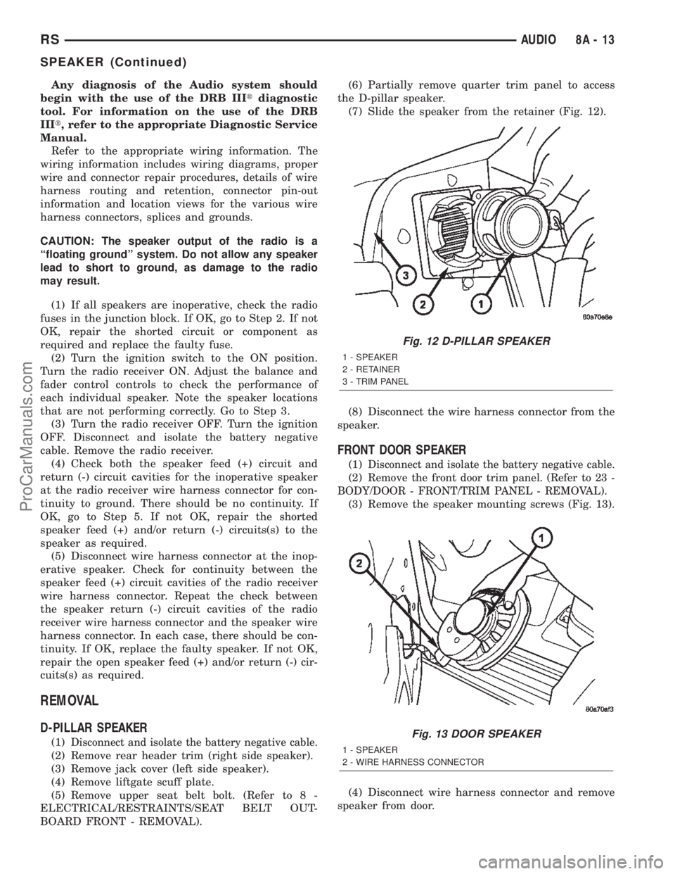
(7) Slide the speaker from the retainer (Fig. 12).
(8) Disconnect the wire harness connector from the
speaker.
FRONT DOOR SPEAKER
(1)Disconnect and isolate the battery negative cable.
(2)Remove the front door trim panel. (Refer to 23 -
BODY/DOOR - FRONT/TRIM PANEL - REMOVAL).
(3) Remove the speaker mounting screws (Fig. 13).
(4) Disconnect wire harness connector and remove
speaker from door.
Fig. 12 D-PILLAR SPEAKER
1 - SPEAKER
2 - RETAINER
3 - TRIM PANEL
Fig. 13 DOOR SPEAKER
1 - SPEAKER
2 - WIRE HARNESS CONNECTOR
RSAUDIO8A-13
SPEAKER (Continued)
ProCarManuals.com
Page 333 of 2399

INSTRUMENT PANEL SPEAKER
(1)Disconnect and isolate the battery negative cable.
(2) Remove the A-pillar trim. (Refer to 23 - BODY/
INTERIOR/A-PILLAR TRIM - REMOVAL).
(3) Remove instrument panel top pad (Refer to 23 -
BODY/INSTRUMENT PANEL/INSTRUMENT
PANEL TOP PAD - REMOVAL).
(4) Remove speaker screws (Fig. 14).
(5) Disconnect wire harness connector and remove
speaker.
QUARTER PANEL SPEAKER
(1)Disconnect and isolate the battery negative cable.
(2) Using a trim stick, gently pry speaker grill
from trim panel.
(3) Remove speaker retaining screws (Fig. 15).
(4) Disconnect wire harness connector and remove
speaker.
INSTALLATION
D-PILLAR SPEAKER
(1) Connect the wire harness connector to the
speaker.
(2) Slide the speaker into the retainer.
(3) Install quarter panel trim.
(4) Install upper seat belt bolt (right side).
(5) Install liftgate scuff plate.
(6) Install rear header trim (right side).(7) Install jack cover (left side).
(8) Connect battery negative cable.
FRONT DOOR SPEAKER
(1) Connect the wire harness connector and install
speaker to door.
(2) Install the speaker mounting screws.
(3) Install the front door trim panel (Refer to 23 -
BODY/DOOR - FRONT/TRIM PANEL - INSTALLA-
TION).
(4) Connect battery negative cable.
INSTRUMENT PANEL SPEAKER
(1) Connect the wire harness connector and install
speaker to instrument panel.
(2) Install the speaker mounting screws.
(3) Install instrument panel top pad (Refer to 23 -
BODY/INSTRUMENT PANEL/INSTRUMENT
PANEL TOP PAD - INSTALLATION).
(4) Install A-pillar trim (Refer to 23 - BODY/INTE-
RIOR/A-PILLAR TRIM - INSTALLATION).
(5) Connect battery negative cable.
QUARTER PANEL SPEAKER
(1) Connect the wire harness connector and install
speaker to trim panel.
(2) Install the speaker mounting screws.
(3) Install speaker grill by pressing into the trim
panel.
(4) Connect battery negative cable.
Fig. 14 INSTRUMENT PANEL SPEAKER
1 - SPEAKER
2 - WIRE HARNESS CONNECTOR
Fig. 15 QUARTER PANEL SPEAKER
1 - SPEAKER
2 - TRIM PANEL
8A - 14 AUDIORS
SPEAKER (Continued)
ProCarManuals.com
Page 340 of 2399
(5) Obtain ignition keys to be programmed from
customer (8 keys maximum).
(6) Using the DRB III, erase all ignition keys by
selecting MISCELLANEOUS and ERASE ALL CUR-
RENT IGN. KEYS.
(7) Program all ignition keys.
Learned Key In Ignition - Ignition key transponder
ID is currently programmed in SKIM memory.
ADJUSTABLE PEDAL MODULE
DIAGNOSIS AND TESTING - ADJUSTABLE
PEDAL MODULE
Refer to Appropriate Diagnostic Information.
REMOVAL
(1) Remove adjustable pedal assembly from vehi-
cle. (Refer to 5 - BRAKES/HYDRAULIC/MECHANI-
CAL/PEDAL - REMOVAL)
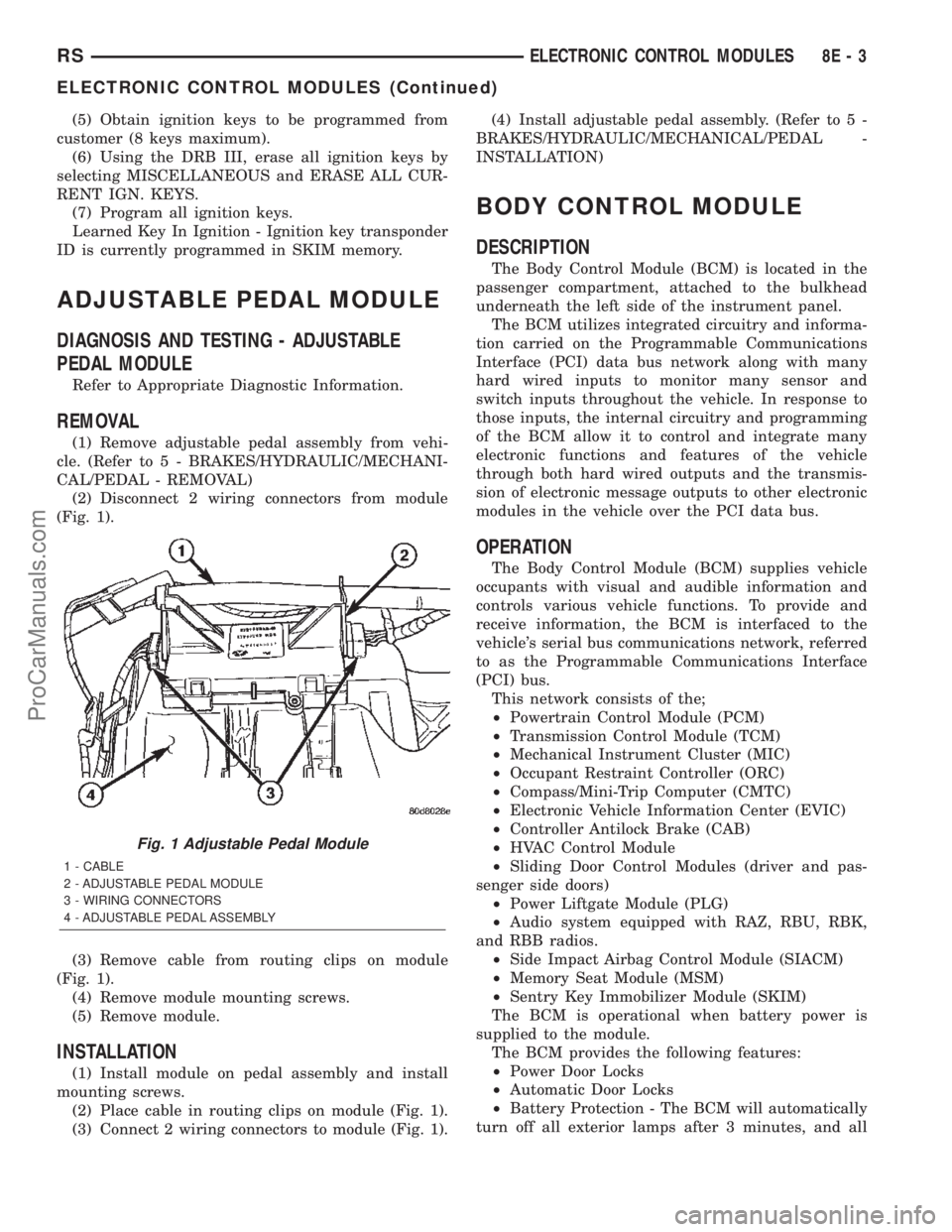
(2) Disconnect 2 wiring connectors from module
(Fig. 1).
(3) Remove cable from routing clips on module
(Fig. 1).
(4) Remove module mounting screws.
(5) Remove module.
INSTALLATION
(1) Install module on pedal assembly and install
mounting screws.
(2) Place cable in routing clips on module (Fig. 1).
(3) Connect 2 wiring connectors to module (Fig. 1).(4) Install adjustable pedal assembly. (Refer to 5 -
BRAKES/HYDRAULIC/MECHANICAL/PEDAL -
INSTALLATION)
BODY CONTROL MODULE
DESCRIPTION
The Body Control Module (BCM) is located in the
passenger compartment, attached to the bulkhead
underneath the left side of the instrument panel.
The BCM utilizes integrated circuitry and informa-
tion carried on the Programmable Communications
Interface (PCI) data bus network along with many
hard wired inputs to monitor many sensor and
switch inputs throughout the vehicle. In response to
those inputs, the internal circuitry and programming
of the BCM allow it to control and integrate many
electronic functions and features of the vehicle
through both hard wired outputs and the transmis-
sion of electronic message outputs to other electronic
modules in the vehicle over the PCI data bus.
OPERATION
The Body Control Module (BCM) supplies vehicle
occupants with visual and audible information and
controls various vehicle functions. To provide and
receive information, the BCM is interfaced to the
vehicle's serial bus communications network, referred
to as the Programmable Communications Interface
(PCI) bus.
This network consists of the;
²Powertrain Control Module (PCM)
²Transmission Control Module (TCM)
²Mechanical Instrument Cluster (MIC)
²Occupant Restraint Controller (ORC)
²Compass/Mini-Trip Computer (CMTC)
²Electronic Vehicle Information Center (EVIC)
²Controller Antilock Brake (CAB)
²HVAC Control Module
²Sliding Door Control Modules (driver and pas-
senger side doors)
²Power Liftgate Module (PLG)
²Audio system equipped with RAZ, RBU, RBK,
and RBB radios.
²Side Impact Airbag Control Module (SIACM)
²Memory Seat Module (MSM)
²Sentry Key Immobilizer Module (SKIM)
The BCM is operational when battery power is
supplied to the module.
The BCM provides the following features:
²Power Door Locks
²Automatic Door Locks
²Battery Protection - The BCM will automatically
turn off all exterior lamps after 3 minutes, and all
Fig. 1 Adjustable Pedal Module
1 - CABLE
2 - ADJUSTABLE PEDAL MODULE
3 - WIRING CONNECTORS
4 - ADJUSTABLE PEDAL ASSEMBLY
RSELECTRONIC CONTROL MODULES8E-3
ELECTRONIC CONTROL MODULES (Continued)
ProCarManuals.com
Page 341 of 2399
interior lamps after 15 minutes after the ignition is
turned off, if they are not turned off by the driver.
²Chime Driver
²Compass/Mini-Trip support.
²Interior Lighting (Courtesy/Reading Lamps)
²BCM Diagnostic Reporting
²Electronic Liftgate Release (with Power Door
Locks)
²Exterior Lighting
²Headlamp Time Delay (with/without Automatic
Headlamps)
²Illuminated Entry
²Fade to Off Interior Lamps - This feature dims
the interior lighting (courtesy lamps) gradually if theBCM does not receive any new inputs that would
cause the interior lamps to remain on.
²Pulse Width Modulated Instrument Panel Dim-
ming
²Door Lock Inhibit - This feature disables the
door lock functions if the key is in the ignition and
either front door is ajar. Pressing the Remote Keyless
Entry (RKE) lock/unlock button under these condi-
tions result in normal lock/unlock activation.
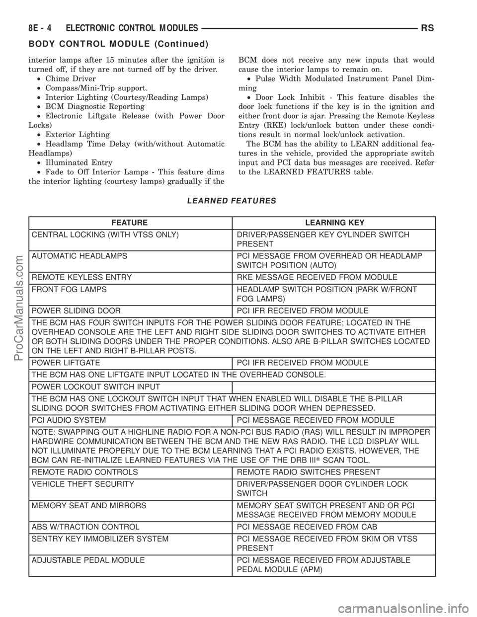
The BCM has the ability to LEARN additional fea-
tures in the vehicle, provided the appropriate switch
input and PCI data bus messages are received. Refer
to the LEARNED FEATURES table.
LEARNED FEATURES
FEATURE LEARNING KEY
CENTRAL LOCKING (WITH VTSS ONLY) DRIVER/PASSENGER KEY CYLINDER SWITCH
PRESENT
AUTOMATIC HEADLAMPS PCI MESSAGE FROM OVERHEAD OR HEADLAMP
SWITCH POSITION (AUTO)
REMOTE KEYLESS ENTRY RKE MESSAGE RECEIVED FROM MODULE
FRONT FOG LAMPS HEADLAMP SWITCH POSITION (PARK W/FRONT
FOG LAMPS)
POWER SLIDING DOOR PCI IFR RECEIVED FROM MODULE
THE BCM HAS FOUR SWITCH INPUTS FOR THE POWER SLIDING DOOR FEATURE; LOCATED IN THE
OVERHEAD CONSOLE ARE THE LEFT AND RIGHT SIDE SLIDING DOOR SWITCHES TO ACTIVATE EITHER
OR BOTH SLIDING DOORS UNDER THE PROPER CONDITIONS. ALSO ARE B-PILLAR SWITCHES LOCATED
ON THE LEFT AND RIGHT B-PILLAR POSTS.
POWER LIFTGATE PCI IFR RECEIVED FROM MODULE
THE BCM HAS ONE LIFTGATE INPUT LOCATED IN THE OVERHEAD CONSOLE.
POWER LOCKOUT SWITCH INPUT
THE BCM HAS ONE LOCKOUT SWITCH INPUT THAT WHEN ENABLED WILL DISABLE THE B-PILLAR
SLIDING DOOR SWITCHES FROM ACTIVATING EITHER SLIDING DOOR WHEN DEPRESSED.
PCI AUDIO SYSTEM PCI MESSAGE RECEIVED FROM MODULE
NOTE: SWAPPING OUT A HIGHLINE RADIO FOR A NON-PCI BUS RADIO (RAS) WILL RESULT IN IMPROPER
HARDWIRE COMMUNICATION BETWEEN THE BCM AND THE NEW RAS RADIO. THE LCD DISPLAY WILL
NOT ILLUMINATE PROPERLY DUE TO THE BCM LEARNING THAT A PCI RADIO EXISTS. HOWEVER, THE
BCM CAN RE-INITIALIZE LEARNED FEATURES VIA THE USE OF THE DRB IIITSCAN TOOL.
REMOTE RADIO CONTROLS REMOTE RADIO SWITCHES PRESENT
VEHICLE THEFT SECURITY DRIVER/PASSENGER DOOR CYLINDER LOCK
SWITCH
MEMORY SEAT AND MIRRORS MEMORY SEAT SWITCH PRESENT AND OR PCI
MESSAGE RECEIVED FROM MEMORY MODULE
ABS W/TRACTION CONTROL PCI MESSAGE RECEIVED FROM CAB
SENTRY KEY IMMOBILIZER SYSTEM PCI MESSAGE RECEIVED FROM SKIM OR VTSS
PRESENT
ADJUSTABLE PEDAL MODULE PCI MESSAGE RECEIVED FROM ADJUSTABLE
PEDAL MODULE (APM)
8E - 4 ELECTRONIC CONTROL MODULESRS
BODY CONTROL MODULE (Continued)
ProCarManuals.com
Page 345 of 2399
²Back-Up switch
²Brake Fluid Level
²B+ Connection Detection
²Engine Crank Signal (Diesel Engine Vehicles)
²Horn Input
²Ignition Switch Start Only
²Ignition Switch Run and Start Only
²Stop Lamp Sense
²Washer Fluid Level
²Windshield Wiper Park
DIAGNOSIS AND TESTING - FRONT CONTROL
MODULE
The Front Control Module (FCM) is a printed cir-
cuit board based module with a on-board micro-pro-
cessor. The FCM interfaces with other electronic
modules in the vehicle via the Programmable Com-
munications Interface (PCI) data bus. In order to
obtain conclusive testing the PCI data bus and all of
the electronic modules that provide inputs to, or
receive outputs from the FCM must be checked. All
PCI communication faults must be resolved prior to
further diagnosing any front control module related
issues.
The FCM was designed to be diagnosed with an
appropriate diagnostic scan tool, such as the DRB
IIIt. The most reliable, efficient, and accurate means
to diagnose the front control module requires the use
of a DRB IIItscan tool and the proper Body Diag-
nostic Procedures manual.
Before any testing of the FCM is attempted, the
battery should be fully charged and all wire harness
and ground connections inspected around the affected
areas on the vehicle.
REMOVAL
(1) Disconnect the positive and negative battery
cables from the battery.
(2) Remove the battery from the vehicle. Refer to
the procedure in Battery Systems.
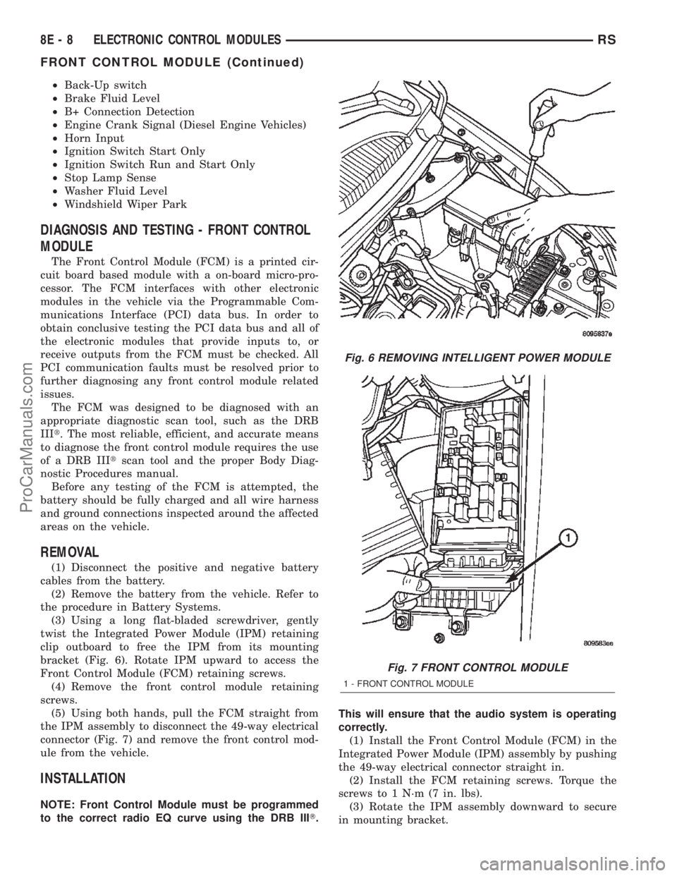
(3) Using a long flat-bladed screwdriver, gently
twist the Integrated Power Module (IPM) retaining
clip outboard to free the IPM from its mounting
bracket (Fig. 6). Rotate IPM upward to access the
Front Control Module (FCM) retaining screws.
(4) Remove the front control module retaining
screws.
(5) Using both hands, pull the FCM straight from
the IPM assembly to disconnect the 49-way electrical
connector (Fig. 7) and remove the front control mod-
ule from the vehicle.
INSTALLATION
NOTE: Front Control Module must be programmed
to the correct radio EQ curve using the DRB IIIT.This will ensure that the audio system is operating
correctly.
(1) Install the Front Control Module (FCM) in the
Integrated Power Module (IPM) assembly by pushing
the 49-way electrical connector straight in.
(2) Install the FCM retaining screws. Torque the
screws to 1 N´m (7 in. lbs).
(3) Rotate the IPM assembly downward to secure
in mounting bracket.
Fig. 6 REMOVING INTELLIGENT POWER MODULE
Fig. 7 FRONT CONTROL MODULE
1 - FRONT CONTROL MODULE
8E - 8 ELECTRONIC CONTROL MODULESRS
FRONT CONTROL MODULE (Continued)
ProCarManuals.com
Page 658 of 2399
WIRING
TABLE OF CONTENTS
page page
WIRING DIAGRAM INFORMATION....... 8W-01-1
COMPONENT INDEX.................. 8W-02-1
POWER DISTRIBUTION............... 8W-10-1
GROUND DISTRIBUTION.............. 8W-15-1
BUS COMMUNICATIONS.............. 8W-18-1
CHARGING SYSTEM.................. 8W-20-1
STARTING SYSTEM.................. 8W-21-1
FUEL/IGNITION SYSTEM.............. 8W-30-1
TRANSMISSION CONTROL SYSTEM..... 8W-31-1
VEHICLE SPEED CONTROL............ 8W-33-1
ANTILOCK BRAKES................... 8W-35-1
VEHICLE THEFT SECURITY SYSTEM..... 8W-39-1
INSTRUMENT CLUSTER............... 8W-40-1
HORN/CIGAR LIGHTER/POWER OUTLET . . 8W-41-1
AIR CONDITIONING-HEATER........... 8W-42-1
AIRBAG SYSTEM.................... 8W-43-1
INTERIOR LIGHTING.................. 8W-44-1
BODY CONTROL MODULE............. 8W-45-1MESSAGE CENTER................... 8W-46-1
AUDIO SYSTEM..................... 8W-47-1
REAR WINDOW DEFOGGER............ 8W-48-1
OVERHEAD CONSOLE................. 8W-49-1
FRONT LIGHTING.................... 8W-50-1
REAR LIGHTING..................... 8W-51-1
TURN SIGNALS...................... 8W-52-1
WIPERS............................ 8W-53-1
TRAILER TOW....................... 8W-54-1
POWER WINDOWS................... 8W-60-1
POWER DOOR LOCKS................ 8W-61-1
POWER MIRRORS................... 8W-62-1
POWER SEATS...................... 8W-63-1
SPLICE INFORMATION................ 8W-70-1
CONNECTOR PIN-OUTS............... 8W-80-1
CONNECTOR/GROUND/SPLICE
LOCATION........................ 8W-91-1
POWER DISTRIBUTION SYSTEM........ 8W-97-1 RSWIRING
8W-1
ProCarManuals.com
Page 665 of 2399
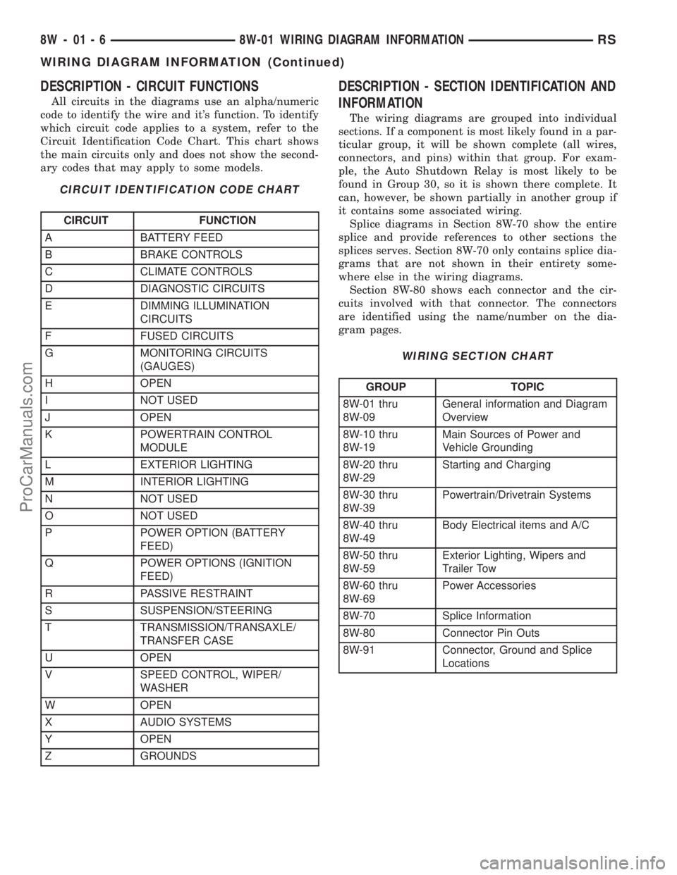
DESCRIPTION - CIRCUIT FUNCTIONS
All circuits in the diagrams use an alpha/numeric
code to identify the wire and it's function. To identify
which circuit code applies to a system, refer to the
Circuit Identification Code Chart. This chart shows
the main circuits only and does not show the second-
ary codes that may apply to some models.
CIRCUIT IDENTIFICATION CODE CHART
CIRCUIT FUNCTION
A BATTERY FEED
B BRAKE CONTROLS
C CLIMATE CONTROLS
D DIAGNOSTIC CIRCUITS
E DIMMING ILLUMINATION
CIRCUITS
F FUSED CIRCUITS
G MONITORING CIRCUITS
(GAUGES)
H OPEN
I NOT USED
J OPEN
K POWERTRAIN CONTROL
MODULE
L EXTERIOR LIGHTING
M INTERIOR LIGHTING
N NOT USED
O NOT USED
P POWER OPTION (BATTERY
FEED)
Q POWER OPTIONS (IGNITION
FEED)
R PASSIVE RESTRAINT
S SUSPENSION/STEERING
T TRANSMISSION/TRANSAXLE/
TRANSFER CASE
U OPEN
V SPEED CONTROL, WIPER/
WASHER
W OPEN
X AUDIO SYSTEMS
Y OPEN
Z GROUNDS
DESCRIPTION - SECTION IDENTIFICATION AND
INFORMATION
The wiring diagrams are grouped into individual
sections. If a component is most likely found in a par-
ticular group, it will be shown complete (all wires,
connectors, and pins) within that group. For exam-
ple, the Auto Shutdown Relay is most likely to be
found in Group 30, so it is shown there complete. It
can, however, be shown partially in another group if
it contains some associated wiring.
Splice diagrams in Section 8W-70 show the entire
splice and provide references to other sections the
splices serves. Section 8W-70 only contains splice dia-
grams that are not shown in their entirety some-
where else in the wiring diagrams.
Section 8W-80 shows each connector and the cir-
cuits involved with that connector. The connectors
are identified using the name/number on the dia-
gram pages.
WIRING SECTION CHART
GROUP TOPIC
8W-01 thru
8W-09General information and Diagram
Overview
8W-10 thru
8W-19Main Sources of Power and
Vehicle Grounding
8W-20 thru
8W-29Starting and Charging
8W-30 thru
8W-39Powertrain/Drivetrain Systems
8W-40 thru
8W-49Body Electrical items and A/C
8W-50 thru
8W-59Exterior Lighting, Wipers and
Trailer Tow
8W-60 thru
8W-69Power Accessories
8W-70 Splice Information
8W-80 Connector Pin Outs
8W-91 Connector, Ground and Splice
Locations
8W - 01 - 6 8W-01 WIRING DIAGRAM INFORMATIONRS
WIRING DIAGRAM INFORMATION (Continued)
ProCarManuals.com