engine warning lamp CHRYSLER VOYAGER 2002 User Guide
[x] Cancel search | Manufacturer: CHRYSLER, Model Year: 2002, Model line: VOYAGER, Model: CHRYSLER VOYAGER 2002Pages: 2399, PDF Size: 57.96 MB
Page 504 of 2399

sage transmitted by the BCM to the FCM to turn off
the headlamps.
OPERATION
AUTOMATIC HEADLAMP SYSTEM
Automatic headlamps are controlled by the Body Con-
trol Module (BCM). With the headlamp switch in the
AUTO position, the BCM will control the headlamp, park-
ing, side marker, tail and instrumentation lamps based on
ambient light levels. Ambient light levels are monitored
by the BCM using the Day/Night signal and Electrochro-
matic Mirror (ECM) present from the Compass Mini Trip
(CMTC) located on the front windshield in front of the
rear view mirror ECM. Ambient light readings are aver-
aged to limit cycling the lamps ON and OFF when pass-
ing through areas with varying light levels. The
automatic headlamps will only function when the engine
is running with RPM > 450. When the headlamp switch is
in the AUTO position (Automatic mode), the Headlamp
Time Delay system will function when the ignition switch
is placed in any position other than run/start.
DAYTIME RUNNING LAMPS
Power is reduced using pulse-width modulation to
the high beams, where by the power is switched on
and off rapidly instead of remaining on continuously.
The duration and interval of the power pulses is pro-
grammed into the FCM.
HEADLAMP SYSTEM
The headlamp system will default to headlamps
ON position when ignition switch is ON and when an
open or short circuit failure occurs on the headlamp
switch input. The system will return to normal oper-
ation when the open or short is repaired. A fault will
be reported by the BCM when a failure occurs on the
dimmer or headlamp switch input.
If the exterior lamps are ON and the headlamp
switch is in any position other than OFF or AUTO
and with the ignition switch OFF (LOCK) after 3
minutes the BCM sends a message via PCI bus to
the FCM informing the FCM to turn off the head-
lamps, park lamps and fog lamps. This feature pre-
vents the vehicle battery from being discharged when
the vehicle lights have been left ON.
HEADLAMP TIME DELAY SYSTEM
The headlamp time delay system is activated by
turning the headlamps ON (high or low beam) while
the engine is running, turning the ignition switch
OFF, and then turning the headlamp switch OFF
within 45 seconds. The system will not activate if
more than 45 seconds elapse between ignition switch
OFF and headlamp switch OFF. The BCM will allow
the headlamps to remain ON for 90 seconds (config-urable) before they automatically turn off (If the key
is in the ignition during the headlamp time delay
mode, then both the headlamps and park lamps
(including panel dimming) will be ON). Refer to the
Owner's Manual for more information.
If the headlamp switch is in the Auto Headlamp
Position, the headlamps are ON due to the night sig-
nal from the CMTC and the ignition switch is in any
position other than run/start, the BCM shall enter a
90 second (configurable) Auto Headlamps time delay
mode. If the key is in the ignition during the head-
lamp time delay mode, then both the headlamps and
park lamps (including panel dimming) will be ON. If
the key is not in the ignition, then only the head-
lamps will be ON. The BCM will allow the head-
lamps to remain ON for 90 seconds before they
automatically turn OFF. Refer to the Owner's Man-
ual for more information.
OPTICAL HORN/HIGH BEAMS
When the multi-function switch is pulled to the
first detent (optical horn) signal, the headlamps are
ON, key-in the ignition the BCM shall send a mes-
sage via PCI bus to the FCM to turn on the head-
lamps drivers to illuminate all four filaments (Low
and High beams). When the multi-function switch is
pulled to the second detent (high beam) signal and
the headlamps are ON, the BCM shall send a mes-
sage via PCI bus to the FCM to turn on the head-
lamps drivers. The High Beams are illuminated and
the Low Beams and Fog Lamps (if ON) are extin-
guished. If the headlamps were in the high beam
configuration when power was removed from the
headlamps, the headlamps will be configured as low
beam the next time they are activated.
WARNING
WARNING: EYE PROTECTION SHOULD BE USED
WHEN SERVICING GLASS COMPONENTS. PER-
SONAL INJURY CAN RESULT.
CAUTION: Do not touch the glass of halogen bulbs
with fingers or other possibly oily surface, reduced
bulb life will result. Do not use bulbs other than
those indicated in the Bulb Application table. Dam-
age to lamp and/or Daytime Running Lamp Module
can result. Do not use fuses, circuit breakers or
relays having greater amperage value than indi-
cated on the fuse panel or in the Owners Manual.
CAUTION: Do not use bulbs other than those listed
in the Bulb Application Table. Damage to lamp can
result. Do not touch halogen bulbs with fingers or
other oily surfaces. Bulb life will be reduced.
RSLAMPS/LIGHTING - EXTERIOR8L-3
LAMPS/LIGHTING - EXTERIOR (Continued)
ProCarManuals.com
Page 650 of 2399
REMOVAL
(1) Disconnect and isolate the battery negative
cable.
(2) Hoist vehicle or support on jack stands.
(3) Disconnect the hose from the nozzle inlet. To
disconnect the headlamp washer hose, push down on
the latch with slight force and pull apart.
(4) Apply a regulated 20 psi of compressed air to
the inlet, so as to fully extend the telescopic unit.
WARNING: IF MORE THAN 20 PSI IS APPLIED TO
THE WASHER INLET, WASHER FLUID MAY SPRAY
OUT OF THE HEADLAMP WASHER. WEAR SAFETY
GLASSES AND DO NOT HAVE AIMING DIRECTLY
TOWARD FACE.
(5) Unsnap cover from telescopic assembly.
(6) Disconnect air supply from washer inlet to fully
retract the telescopic unit.
(7) Remove two screws holding the nozzle assem-
bly to the front fascia.
(8) Remove the nozzle assembly from behind fas-
cia.
INSTALLATION
(1) Place the nozzle assembly in behind the fascia.
(2) Install the two screws holding the nozzle
assembly to the front fascia.
(3) Snap cover onto telescopic assembly.
WARNING: IF MORE THAN 20 PSI IS APPLIED TO
THE WASHER INLET, WASHER FLUID MAY SPRAY
OUT OF THE HEADLAMP WASHER. WEAR SAFETY
GLASSES AND DO NOT HAVE AIMING DIRECTLY
TOWARD FACE.
On the new washer unit, there is a white tab with
pull ring holding the telescopic unit up approxi-
mately an inch. This is to ease the installation pro-
cess. Once cover is snapped on, you may either pull
up on the unit to remove the tab, or apply regulated
compressed air.
(4) Apply a regulated 20 psi of compressed air the
inlet, so as to fully extend the telescopic unit.
(5) With unit extended, pull white tab out from the
bottom of the telescopic unit and discard.
(6) Remove the air supply from the washer unit.
(7) Connect the washer hose to the telescopic unit.
Press firmly until snap is heard.
(8) Remove vehicle from hoist or jack stands.
(9) Connect the battery negative cable.
(10) Verify vehicle and system operation.
HEADLAMP WASHER HOSE -
EXPORT
REMOVAL
The headlamp washer hose is a special high pres-
sure hose with specific fittings, and must be replaced
as a unit.
(1) Disconnect and isolate the battery negative
cable.
(2) Hoist vehicle or support on jack stands.
(3) Remove parts as necessary to replace high
pressure headlamp washer hose. When disconnecting
hose, press down firmly on latch at headlamp washer
pump motor and telescopic washer assembly and pull
apart.
INSTALLATION
The headlamp washer hose is a special high pres-
sure hose with specific fittings, and must be replaced
as a unit.
(1) Install the new high pressure headlamp
washer hose assembly. Push fitting on until a snap is
heard.
(2) Install the parts that were removed to replace
high pressure headlamp washer hose.
(3) Remove vehicle from hoist or jack stands.
(4) Connect the battery negative cable.
(5) Verify vehicle and system operation.
HEADLAMP WASHER PUMP
MOTOR - EXPORT
REMOVAL
(1) Disconnect and isolate the battery negative
cable.
(2) Remove the engine fresh air housing inside the
engine compartment (Refer to 9 - ENGINE/AIR
INTAKE SYSTEM/AIR CLEANER HOUSING -
REMOVAL).
(3) Disconnect the washer hose at the in-line con-
nector forward of the cowl grille so that the in-line
connector remains with the washer hose from the
fresh air plenum.
(4) Disconnect the washer hose from the hose clip
located on the front fender side shield.
(5) Remove the filler tube screw.
(6) Hoist and support vehicle on hoist or jack
stands.
(7) Remove the right front wheel and tire assembly
(Refer to 22 - TIRES/WHEELS - REMOVAL).
(8) Disconnect the left right front wheelhouse
splash shield and move aside (Refer to 23 - BODY/
EXTERIOR/WHEELHOUSE SPLASH SHIELD -
REMOVAL).
RSWIPERS/WASHERS8R-13
HEADLAMP WASHERS - EXPORT (Continued)
ProCarManuals.com
Page 1425 of 2399
OPERATION
The exhaust system contains, quiets, and cleans
the exhaust gases generated by the engine.
DIAGNOSIS AND TESTING
DIAGNOSIS AND TESTING - EXCESSIVE
EXHAUST SYSTEM NOISE
CONDITION POSSIBLE CAUSES CORRECTION
EXCESSIVE EXHAUST NOISE
(UNDER HOOD)1. Exhaust manifold cracked or
broken.1. Replace manifold.
2. Manifold to cylinder head leak. 2. Tighten manifold and/or replace
gasket.
3. EGR Valve to manifold gasket
leakage.3. Tighten fasteners or replace
gasket.
4. EGR Valve to EGR tube gasket
leakage.4. Tighten fasteners or replace
gasket.
5. EGR tube to manifold tube
leakage.5. Tighten tube nut.
6. Exhaust flex-joint to manifold
leak.6. Tighten joint fasteners and/or
replace gasket.
7. Exhaust flex-joint. 7. Replace catalytic converter
assembly.
8. Pipe and shell noise from front
exhaust pipe.8. Characteristic of single wall pipe.
EXCESSIVE EXHAUST NOISE 1. Leak at exhaust pipe joints. 1. Tighten clamps at leaking joints.
2. Burned or rusted out muffler
assembly or exhaust pipe.2. Replace muffler resonator tailpipe
assembly or exhaust pipe with
catalytic converter assembly.
3. Burned or rusted out resonator. 3. Replace muffler resonator tailpipe
assembly.
4. Restriction in exhaust system. 4. Perform Exhaust System
Restriction Check. Replace
component as necessary.
5. Converter material in muffler. 5. Replace muffler and converter
assemblies. Check fuel injection and
ignition systems for proper
operation.
DIAGNOSIS AND TESTING - EXHAUST SYSTEM
RESTRICTION CHECK
Exhaust system restriction can be checked by mea-
suring back pressure using the DRB IIItand PEP
module pressure tester.WARNING: THE NORMAL OPERATING TEMPERA-
TURE OF THE EXHAUST SYSTEM IS VERY HIGH.
THEREFORE, NEVER WORK AROUND OR ATTEMPT
TO SERVICE ANY PART OF THE EXHAUST SYSTEM
UNTIL IT IS COOLED. SPECIAL CARE SHOULD BE
TAKEN WHEN WORKING NEAR THE CATALYTIC
CONVERTER. THE TEMPERATURE OF THE CON-
VERTER RISES TO A HIGH LEVEL AFTER A SHORT
PERIOD OF ENGINE OPERATION TIME.
11 - 2 EXHAUST SYSTEMRS
EXHAUST SYSTEM (Continued)
ProCarManuals.com
Page 1457 of 2399

INSTALLATION
(1) Insert level sensor wires into bottom of opening
in module.
(2) Wrap wires into groove in back of level sensor
(Fig. 7) .
(3) While feeding wires into guide grooves, slide
level sensor up into channel until it snaps into place
(Fig. 8) . Ensure tab at bottom of sensor locks in
place.
(4) Install level sensor wires in connector. Push
the wires up through the connector and then pull
them down until they lock in place. Ensure signal
and ground wires are installed in the correct posi-
tion.
(5) Install locking wedge on connector.
(6) Push connector up into bottom of fuel pump
module electrical connector.(7) Install fuel pump module. Refer to Fuel Pump
Module in this section.
FUEL LINES
DESCRIPTION - FUEL LINES/HOSES AND
CLAMPS
Also refer to Quick-Connect Fittings.
WARNING: THE FUEL SYSTEM IS UNDER A CON-
STANT PRESSURE (EVEN WITH THE ENGINE OFF).
BEFORE SERVICING ANY FUEL SYSTEM HOSES,
FITTINGS OR LINES, THE FUEL SYSTEM PRES-
SURE MUST BE RELEASED. REFER TO THE FUEL
SYSTEM PRESSURE RELEASE PROCEDURE IN
THIS GROUP.
The lines/tubes/hoses used on fuel injected vehicles
are of a special construction. This is due to the
higher fuel pressures and the possibility of contami-
nated fuel in this system. If it is necessary to replace
these lines/tubes/hoses, only those marked EFM/EFI
may be used.
If equipped:The hose clamps used to secure rub-
ber hoses on fuel injected vehicles are of a special
rolled edge construction. This construction is used to
prevent the edge of the clamp from cutting into the
hose. Only these rolled edge type clamps may be
used in this system. All other types of clamps may
cut into the hoses and cause high-pressure fuel leaks.
Use new original equipment type hose clamps.
STANDARD PROCEDURE - HOSES AND CLAMP
Inspect all hose connections (clamps and quick con-
nect fittings) for completeness and leaks. Replace
cracked, scuffed, or swelled hoses. Replace hoses that
rub against other vehicle components or show sign of
wear.
Fuel injected vehicles use specially constructed
hoses. When replacing hoses, only use hoses marked
EFM/EFI.
When installing hoses, ensure that they are routed
away from contact with other vehicle components
that could rub against them and cause failure. Avoid
contact with clamps or other components that cause
abrasions or scuffing. Ensure that rubber hoses are
properly routed and avoid heat sources.
The hose clamps have rolled edges to prevent the
clamp from cutting into the hose. Only use clamps
that are original equipment or equivalent. Other
types of clamps may cut into the hoses and cause
high pressure fuel leaks. Tighten hose clamps to 1
N´m (10 in. lbs.) torque.
Inspect all hose connections such as clamps, cou-
plings and fittings to make sure they are secure and
Fig. 7 Groove in Back Side of Level Sensor
1 - WRAP WIRES IN GROOVE
2 - REAR VIEW OF LEVEL SENSOR
Fig. 8 Installation Channel
1 - CHANNEL FOR LEVEL SENSOR
2 - PUMP MODULE
14 - 6 FUEL DELIVERYRS
FUEL LEVEL SENDING UNIT / SENSOR (Continued)
ProCarManuals.com
Page 1460 of 2399
WARNING: THE FUEL RESERVOIR OF THE FUEL
PUMP MODULE DOES NOT EMPTY OUT WHEN THE
TANK IS DRAINED. THE FUEL IN THE RESERVOIR
MAY SPILL OUT WHEN THE MODULE IS REMOVED.
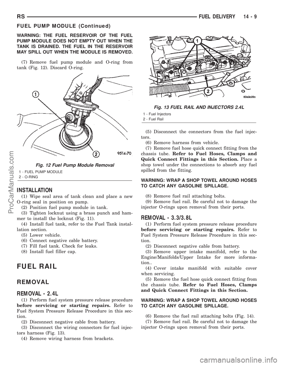
(7) Remove fuel pump module and O-ring from
tank (Fig. 12). Discard O-ring.
INSTALLATION
(1) Wipe seal area of tank clean and place a new
O-ring seal in position on pump.
(2) Position fuel pump module in tank.
(3) Tighten locknut using a brass punch and ham-
mer to install the locknut (Fig. 11).
(4) Install fuel tank, refer to the Fuel Tank instal-
lation section.
(5) Lower vehicle.
(6) Connect negative cable battery.
(7) Fill fuel tank. Check for leaks.
(8) Install fuel filler cap.
FUEL RAIL
REMOVAL
REMOVAL - 2.4L
(1) Perform fuel system pressure release procedure
before servicing or starting repairs.Refer to
Fuel System Pressure Release Procedure in this sec-
tion.
(2) Disconnect negative cable from battery.
(3) Disconnect the wiring connectors for fuel injec-
tors harness (Fig. 13).
(4) Remove wiring harness from brackets.(5) Disconnect the connectors from the fuel injec-
tors.
(6) Remove harness from vehicle.
(7) Remove fuel hose quick connect fitting from the
chassis tube.Refer to Fuel Hoses, Clamps and
Quick Connect Fittings in this Section.Place a
shop towel under the connections to absorb any fuel
spilled from the fitting.
WARNING: WRAP A SHOP TOWEL AROUND HOSES
TO CATCH ANY GASOLINE SPILLAGE.
(8) Remove fuel rail attaching bolts.
(9) Remove fuel rail. Be careful not to damage the
injector O-rings upon removal from their ports.
REMOVAL - 3.3/3.8L
(1) Perform fuel system pressure release procedure
before servicing or starting repairs.Refer to
Fuel System Pressure Release Procedure in this sec-
tion.
(2) Disconnect negative cable from battery.
(3) Remove upper intake manifold, refer to the
Engine/Manifolds/Upper Intake for more informa-
tion..
(4) Cover intake manifold with suitable cover
when servicing.
(5) Remove the fuel hose quick connect fitting from
the chassis tube.Refer to Fuel Hoses, Clamps
and Quick Connect Fittings in this Section.
WARNING: WRAP A SHOP TOWEL AROUND HOSES
TO CATCH ANY GASOLINE SPILLAGE.
(6) Remove the fuel rail attaching bolts (Fig. 14).
(7) Remove fuel rail. Be careful not to damage the
injector O-rings upon removal from their ports.
Fig. 12 Fuel Pump Module Removal
1 - FUEL PUMP MODULE
2 - O-RING
Fig. 13 FUEL RAIL AND INJECTORS 2.4L
1 - Fuel Injectors
2 - Fuel Rail
RSFUEL DELIVERY14-9
FUEL PUMP MODULE (Continued)
ProCarManuals.com
Page 1497 of 2399
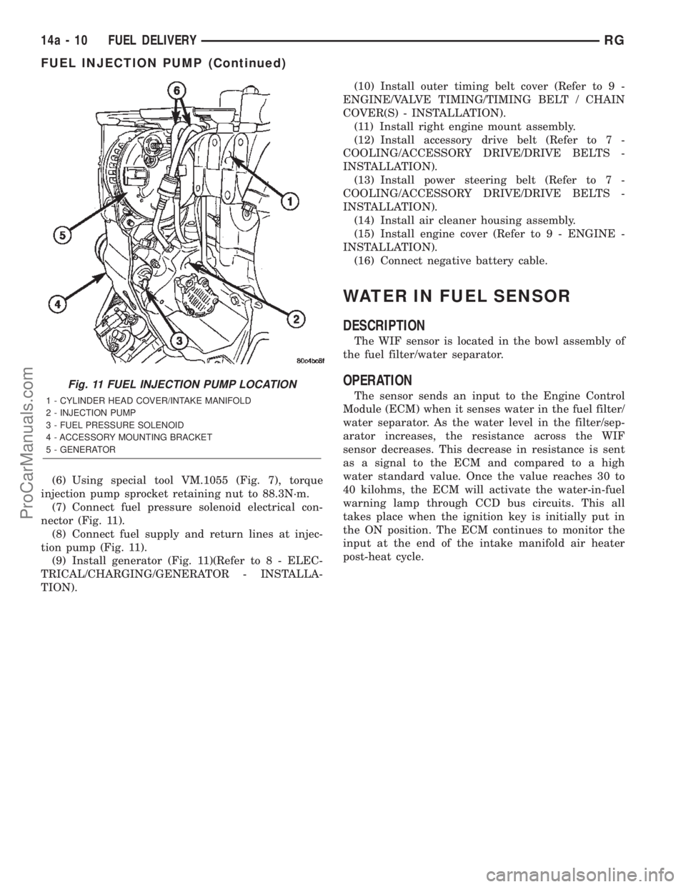
(6) Using special tool VM.1055 (Fig. 7), torque
injection pump sprocket retaining nut to 88.3N´m.
(7) Connect fuel pressure solenoid electrical con-
nector (Fig. 11).
(8) Connect fuel supply and return lines at injec-
tion pump (Fig. 11).
(9) Install generator (Fig. 11)(Refer to 8 - ELEC-
TRICAL/CHARGING/GENERATOR - INSTALLA-
TION).(10) Install outer timing belt cover (Refer to 9 -
ENGINE/VALVE TIMING/TIMING BELT / CHAIN
COVER(S) - INSTALLATION).
(11) Install right engine mount assembly.
(12) Install accessory drive belt (Refer to 7 -
COOLING/ACCESSORY DRIVE/DRIVE BELTS -
INSTALLATION).
(13) Install power steering belt (Refer to 7 -
COOLING/ACCESSORY DRIVE/DRIVE BELTS -
INSTALLATION).
(14) Install air cleaner housing assembly.
(15) Install engine cover (Refer to 9 - ENGINE -
INSTALLATION).
(16) Connect negative battery cable.
WATER IN FUEL SENSOR
DESCRIPTION
The WIF sensor is located in the bowl assembly of
the fuel filter/water separator.
OPERATION
The sensor sends an input to the Engine Control
Module (ECM) when it senses water in the fuel filter/
water separator. As the water level in the filter/sep-
arator increases, the resistance across the WIF
sensor decreases. This decrease in resistance is sent
as a signal to the ECM and compared to a high
water standard value. Once the value reaches 30 to
40 kilohms, the ECM will activate the water-in-fuel
warning lamp through CCD bus circuits. This all
takes place when the ignition key is initially put in
the ON position. The ECM continues to monitor the
input at the end of the intake manifold air heater
post-heat cycle.
Fig. 11 FUEL INJECTION PUMP LOCATION
1 - CYLINDER HEAD COVER/INTAKE MANIFOLD
2 - INJECTION PUMP
3 - FUEL PRESSURE SOLENOID
4 - ACCESSORY MOUNTING BRACKET
5 - GENERATOR
14a - 10 FUEL DELIVERYRG
FUEL INJECTION PUMP (Continued)
ProCarManuals.com
Page 1547 of 2399
NOTE: Before installing power steering pressure
hose on power steering pump, inspect the O-ring
on the power steering pressure hose for damage
and replace if required.
(4) Install the power steering fluid pressure hose
fitting into the pressure port of the power steering
pump (Fig. 12). Tighten the pressure line to pump
fitting tube nut to a torque of 31 N´m (275 in. lbs.).
(5) Install the power steering fluid supply hose on
the power steering pump supply fitting (Fig. 12).Be
sure hose clamp is properly reinstalled.
(6) Install the accessary drive belt (Refer to 7 -
COOLING/ACCESSORY DRIVE/DRIVE BELTS -
INSTALLATION).
(7) Install the splash shields below the engine
compartment.
(8) Lower the vehicle.
(9) Connect the negative (-) battery cable on the
negative battery post.
(10) Fill and bleed the power steering system
using the Power Steering Pump Initial Operation
Procedure (Refer to 19 - STEERING/PUMP - STAN-
DARD PROCEDURE).
(11) Inspect for leaks.
SPECIAL TOOLS
POWER STEERING PUMP
FLUID
STANDARD PROCEDURE - POWER STEERING
FLUID LEVEL CHECKING
WARNING: FLUID LEVEL SHOULD BE CHECKED
WITH THE ENGINE OFF TO PREVENT INJURY
FROM MOVING PARTS AND TO ENSURE ACCU-
RATE FLUID LEVEL READING.
The fluid level can be read on the exterior of the
power steering fluid reservoir. The fluid level should
be within the ªFILL RANGEº when the fluid is at
normal ambient temperature, approximately 21ÉC to
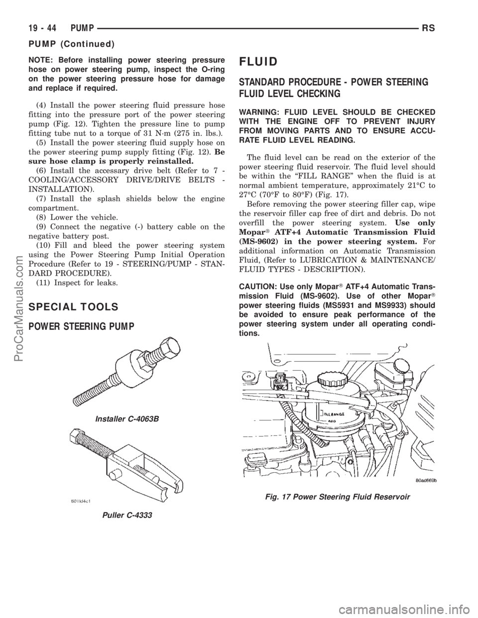
27ÉC (70ÉF to 80ÉF) (Fig. 17).
Before removing the power steering filler cap, wipe
the reservoir filler cap free of dirt and debris. Do not
overfill the power steering system.Use only
MopartATF+4 Automatic Transmission Fluid
(MS-9602) in the power steering system.For
additional information on Automatic Transmission
Fluid, (Refer to LUBRICATION & MAINTENANCE/
FLUID TYPES - DESCRIPTION).
CAUTION: Use only MoparTATF+4 Automatic Trans-
mission Fluid (MS-9602). Use of other MoparT
power steering fluids (MS5931 and MS9933) should
be avoided to ensure peak performance of the
power steering system under all operating condi-
tions.
Installer C-4063B
Puller C-4333
Fig. 17 Power Steering Fluid Reservoir
19 - 44 PUMPRS
PUMP (Continued)
ProCarManuals.com
Page 1548 of 2399
FLUID COOLER
DESCRIPTION
All models (except 2.5L Diesel) are equipped with a
cooler for the power steering system fluid. The power
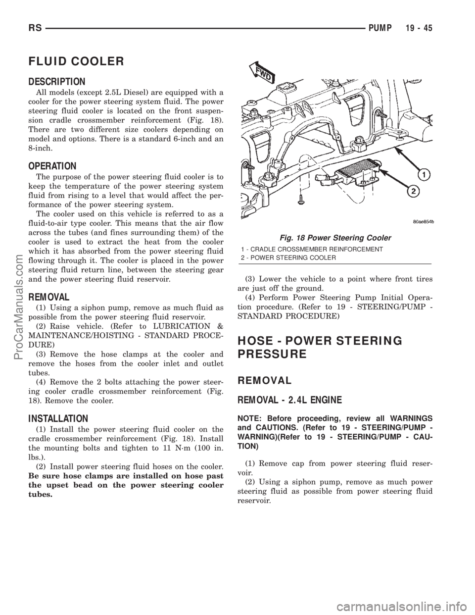
steering fluid cooler is located on the front suspen-
sion cradle crossmember reinforcement (Fig. 18).
There are two different size coolers depending on
model and options. There is a standard 6-inch and an
8-inch.
OPERATION
The purpose of the power steering fluid cooler is to
keep the temperature of the power steering system
fluid from rising to a level that would affect the per-
formance of the power steering system.
The cooler used on this vehicle is referred to as a
fluid-to-air type cooler. This means that the air flow
across the tubes (and fines surrounding them) of the
cooler is used to extract the heat from the cooler
which it has absorbed from the power steering fluid
flowing through it. The cooler is placed in the power
steering fluid return line, between the steering gear
and the power steering fluid reservoir.
REMOVAL
(1) Using a siphon pump, remove as much fluid as
possible from the power steering fluid reservoir.
(2) Raise vehicle. (Refer to LUBRICATION &
MAINTENANCE/HOISTING - STANDARD PROCE-
DURE)
(3) Remove the hose clamps at the cooler and
remove the hoses from the cooler inlet and outlet
tubes.
(4) Remove the 2 bolts attaching the power steer-
ing cooler cradle crossmember reinforcement (Fig.
18). Remove the cooler.
INSTALLATION
(1) Install the power steering fluid cooler on the
cradle crossmember reinforcement (Fig. 18). Install
the mounting bolts and tighten to 11 N´m (100 in.
lbs.).
(2) Install power steering fluid hoses on the cooler.
Be sure hose clamps are installed on hose past
the upset bead on the power steering cooler
tubes.(3) Lower the vehicle to a point where front tires
are just off the ground.
(4) Perform Power Steering Pump Initial Opera-
tion procedure. (Refer to 19 - STEERING/PUMP -
STANDARD PROCEDURE)
HOSE - POWER STEERING
PRESSURE
REMOVAL
REMOVAL - 2.4L ENGINE
NOTE: Before proceeding, review all WARNINGS
and CAUTIONS. (Refer to 19 - STEERING/PUMP -
WARNING)(Refer to 19 - STEERING/PUMP - CAU-
TION)
(1) Remove cap from power steering fluid reser-
voir.
(2) Using a siphon pump, remove as much power
steering fluid as possible from power steering fluid
reservoir.
Fig. 18 Power Steering Cooler
1 - CRADLE CROSSMEMBER REINFORCEMENT
2 - POWER STEERING COOLER
RSPUMP19-45
ProCarManuals.com
Page 1549 of 2399
(3) Raise vehicle. (Refer to LUBRICATION &
MAINTENANCE/HOISTING - STANDARD PROCE-
DURE)
(4) Remove front emissions vapor canister. (Refer
to 25 - EMISSIONS CONTROL/EVAPORATIVE
EMISSIONS/VAPOR CANISTER - REMOVAL)
(5) Place an oil drain pan under vehicle to catch
power steering fluid.
(6) Back out pressure hose tube nut at power
steering pump pressure fitting and remove hose from
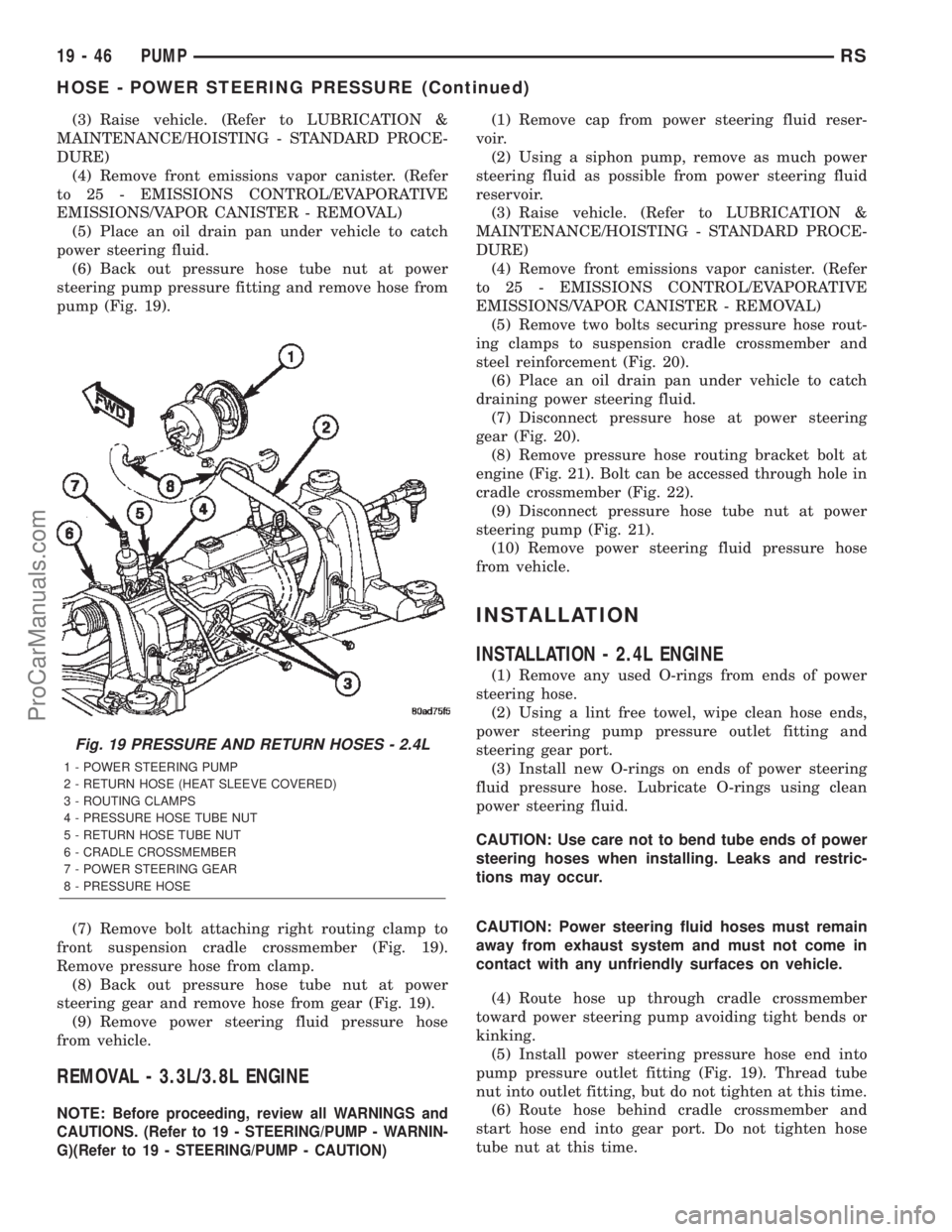
pump (Fig. 19).
(7) Remove bolt attaching right routing clamp to
front suspension cradle crossmember (Fig. 19).
Remove pressure hose from clamp.
(8) Back out pressure hose tube nut at power
steering gear and remove hose from gear (Fig. 19).
(9) Remove power steering fluid pressure hose
from vehicle.
REMOVAL - 3.3L/3.8L ENGINE
NOTE:Before proceeding, review all WARNINGS and
CAUTIONS. (Refer to 19 - STEERING/PUMP - WARNIN-
G)(Refer to 19 - STEERING/PUMP - CAUTION)
(1) Remove cap from power steering fluid reser-
voir.
(2) Using a siphon pump, remove as much power
steering fluid as possible from power steering fluid
reservoir.
(3) Raise vehicle. (Refer to LUBRICATION &
MAINTENANCE/HOISTING - STANDARD PROCE-
DURE)
(4) Remove front emissions vapor canister. (Refer
to 25 - EMISSIONS CONTROL/EVAPORATIVE
EMISSIONS/VAPOR CANISTER - REMOVAL)
(5) Remove two bolts securing pressure hose rout-
ing clamps to suspension cradle crossmember and
steel reinforcement (Fig. 20).
(6) Place an oil drain pan under vehicle to catch
draining power steering fluid.
(7) Disconnect pressure hose at power steering
gear (Fig. 20).
(8) Remove pressure hose routing bracket bolt at
engine (Fig. 21). Bolt can be accessed through hole in
cradle crossmember (Fig. 22).
(9) Disconnect pressure hose tube nut at power
steering pump (Fig. 21).
(10) Remove power steering fluid pressure hose
from vehicle.
INSTALLATION
INSTALLATION - 2.4L ENGINE
(1) Remove any used O-rings from ends of power
steering hose.
(2) Using a lint free towel, wipe clean hose ends,
power steering pump pressure outlet fitting and
steering gear port.
(3) Install new O-rings on ends of power steering
fluid pressure hose. Lubricate O-rings using clean
power steering fluid.
CAUTION: Use care not to bend tube ends of power
steering hoses when installing. Leaks and restric-
tions may occur.
CAUTION: Power steering fluid hoses must remain
away from exhaust system and must not come in
contact with any unfriendly surfaces on vehicle.
(4) Route hose up through cradle crossmember
toward power steering pump avoiding tight bends or
kinking.
(5) Install power steering pressure hose end into
pump pressure outlet fitting (Fig. 19). Thread tube
nut into outlet fitting, but do not tighten at this time.
(6) Route hose behind cradle crossmember and
start hose end into gear port. Do not tighten hose
tube nut at this time.
Fig. 19 PRESSURE AND RETURN HOSES - 2.4L
1 - POWER STEERING PUMP
2 - RETURN HOSE (HEAT SLEEVE COVERED)
3 - ROUTING CLAMPS
4 - PRESSURE HOSE TUBE NUT
5 - RETURN HOSE TUBE NUT
6 - CRADLE CROSSMEMBER
7 - POWER STEERING GEAR
8 - PRESSURE HOSE
19 - 46 PUMPRS
HOSE - POWER STEERING PRESSURE (Continued)
ProCarManuals.com
Page 1552 of 2399
(10) Tighten hose tube nut at power steering gear
port to 31 N´m (275 in. lbs.) torque.
(11) Install front emissions vapor canister. (Refer
to 25 - EMISSIONS CONTROL/EVAPORATIVE
EMISSIONS/VAPOR CANISTER - INSTALLATION)
(12) Lower vehicle.
(13) Fill and bleed the power steering system
using the Power Steering Pump Initial Operation
Procedure. (Refer to 19 - STEERING/PUMP - STAN-
DARD PROCEDURE)
(14) Inspect system for leaks.
HOSE - POWER STEERING
RETURN
REMOVAL
REMOVAL - 2.4L ENGINE
NOTE: Before proceeding, review all WARNINGS
and CAUTIONS. (Refer to 19 - STEERING/PUMP -
WARNING)(Refer to 19 - STEERING/PUMP - CAU-
TION)
(1) Remove cap from power steering fluid reser-
voir.
(2) Using a siphon pump, remove as much power
steering fluid as possible from power steering fluid
reservoir.
(3) Raise vehicle. (Refer to LUBRICATION &
MAINTENANCE/HOISTING - STANDARD PROCE-
DURE)
(4) Remove front emissions vapor canister. (Refer
to 25 - EMISSIONS CONTROL/EVAPORATIVE
EMISSIONS/VAPOR CANISTER - REMOVAL)
(5) Place an oil drain pan under vehicle to catch
power steering fluid.
(6) Cut tie-strap securing insulating heat sleeve to
power steering fluid return hose near power steering
pump. Pull back heat sleeve to expose hose clamp.
(7) Remove clamp, then return hose from power
steering pump (Fig. 19).
(8) Remove 2 bolts attaching power steering cooler
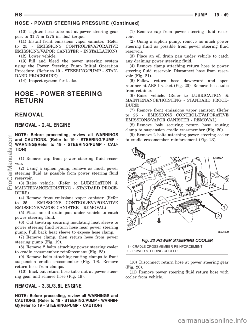
to cradle crossmember reinforcement (Fig. 23).
(9) Remove bolts attaching routing clamps to front
suspension cradle crossmember (Fig. 19). Remove
return hose from clamps.
(10) Back out return hose tube nut at power steer-
ing gear and remove hose (Fig. 19).
REMOVAL - 3.3L/3.8L ENGINE
NOTE:Before proceeding, review all WARNINGS and
CAUTIONS. (Refer to 19 - STEERING/PUMP - WARNIN-
G)(Refer to 19 - STEERING/PUMP - CAUTION)
(1) Remove cap from power steering fluid reser-
voir.
(2) Using a siphon pump, remove as much power
steering fluid as possible from power steering fluid
reservoir.
(3) Place an oil drain pan under vehicle to catch
any draining power steering fluid.
(4) Remove clamp attaching return hose to power
steering fluid reservoir. Disconnect hose from reser-
voir (Fig. 21).
(5) Follow return hose downward and open
retainer at ABS bracket (Fig. 20). Remove hose tube
from retainer.
(6) Raise vehicle. (Refer to LUBRICATION &
MAINTENANCE/HOISTING - STANDARD PROCE-
DURE)
(7) Remove front emissions vapor canister. (Refer
to 25 - EMISSIONS CONTROL/EVAPORATIVE
EMISSIONS/VAPOR CANISTER - REMOVAL)
(8) Remove bolt securing return hose routing
clamp to suspension cradle crossmember (Fig. 20).
(9) Remove 2 bolts attaching power steering cooler
to cradle crossmember reinforcement (Fig. 23).
(10) Disconnect return hose at power steering gear
(Fig. 20).
(11) Remove power steering fluid return hose with
cooler from vehicle.
Fig. 23 POWER STEERING COOLER
1 - CRADLE CROSSMEMBER REINFORCEMENT
2 - POWER STEERING COOLER
RSPUMP19-49
HOSE - POWER STEERING PRESSURE (Continued)
ProCarManuals.com