engine warning lamp CHRYSLER VOYAGER 2002 Service Manual
[x] Cancel search | Manufacturer: CHRYSLER, Model Year: 2002, Model line: VOYAGER, Model: CHRYSLER VOYAGER 2002Pages: 2399, PDF Size: 57.96 MB
Page 6 of 2399
FASTENER USAGE
DESCRIPTION
DESCRIPTION - FASTENER USAGE
WARNING: USE OF AN INCORRECT FASTENER
MAY RESULT IN COMPONENT DAMAGE OR PER-
SONAL INJURY.
Fasteners and torque specifications references in
this Service Manual are identified in metric and SAE
format.
During any maintenance or repair procedures, it is
important to salvage all fasteners (nuts, bolts, etc.)
for reassembly. If the fastener is not salvageable, a
fastener of equivalent specification must be used.
DESCRIPTION - THREADED HOLE REPAIR
Most stripped threaded holes can be repaired using
a Helicoilt. Follow the vehicle or Helicoiltrecommen-
dations for application and repair procedures.
INTERNATIONAL SYMBOLS
DESCRIPTION
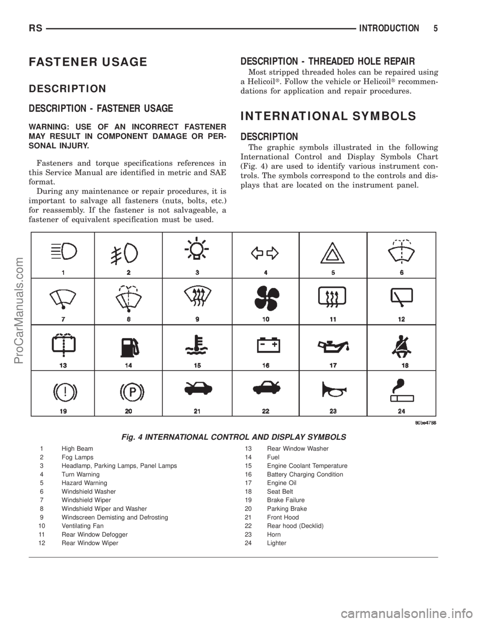
The graphic symbols illustrated in the following
International Control and Display Symbols Chart
(Fig. 4) are used to identify various instrument con-
trols. The symbols correspond to the controls and dis-
plays that are located on the instrument panel.
Fig. 4 INTERNATIONAL CONTROL AND DISPLAY SYMBOLS
1 High Beam 13 Rear Window Washer
2 Fog Lamps 14 Fuel
3 Headlamp, Parking Lamps, Panel Lamps 15 Engine Coolant Temperature
4 Turn Warning 16 Battery Charging Condition
5 Hazard Warning 17 Engine Oil
6 Windshield Washer 18 Seat Belt
7 Windshield Wiper 19 Brake Failure
8 Windshield Wiper and Washer 20 Parking Brake
9 Windscreen Demisting and Defrosting 21 Front Hood
10 Ventilating Fan 22 Rear hood (Decklid)
11 Rear Window Defogger 23 Horn
12 Rear Window Wiper 24 Lighter
RSINTRODUCTION5
ProCarManuals.com
Page 20 of 2399
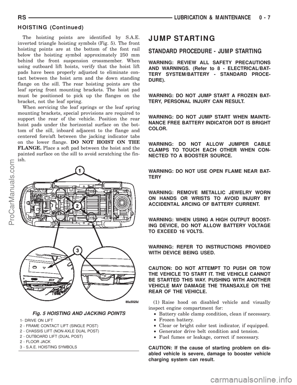
The hoisting points are identified by S.A.E.
inverted triangle hoisting symbols (Fig. 5). The front
hoisting points are at the bottom of the font rail
below the hoisting symbol approximately 250 mm
behind the front suspension crossmember. When
using outboard lift hoists, verify that the hoist lift
pads have been properly adjusted to eliminate con-
tact between the hoist arm and the down standing
flange on the sill. The rear hoisting points are the
leaf spring front mounting brackets. The hoist pad
must be positioned to pick up the flanges on the
bracket, not the leaf spring.
When servicing the leaf springs or the leaf spring
mounting brackets, special provisions are required to
support the rear of the vehicle. Position the rear
hoist pads under the horizontal surface on the bot-
tom of the sill, inboard adjacent to the flange and
centered fore/aft between the jacking indicator tabs
on the lower flange.DO NOT HOIST ON THE
FLANGE.Place a soft pad between the hoist and the
painted surface on the sill to avoid scratching the fin-
ish.JUMP STARTING
STANDARD PROCEDURE - JUMP STARTING
WARNING: REVIEW ALL SAFETY PRECAUTIONS
AND WARNINGS. (Refer to 8 - ELECTRICAL/BAT-
TERY SYSTEM/BATTERY - STANDARD PROCE-
DURE).
WARNING: DO NOT JUMP START A FROZEN BAT-
TERY, PERSONAL INJURY CAN RESULT.
WARNING: DO NOT JUMP START WHEN MAINTE-
NANCE FREE BATTERY INDICATOR DOT IS BRIGHT
COLOR.
WARNING: DO NOT ALLOW JUMPER CABLE
CLAMPS TO TOUCH EACH OTHER WHEN CON-
NECTED TO A BOOSTER SOURCE.
WARNING: DO NOT USE OPEN FLAME NEAR BAT-
TERY
WARNING: REMOVE METALLIC JEWELRY WORN
ON HANDS OR WRISTS TO AVOID INJURY BY
ACCIDENTAL ARCING OF BATTERY CURRENT.
WARNING: WHEN USING A HIGH OUTPUT BOOST-
ING DEVICE, DO NOT ALLOW BATTERY VOLTAGE
TO EXCEED 16 VOLTS.
WARNING: REFER TO INSTRUCTIONS PROVIDED
WITH DEVICE BEING USED.
CAUTION: DO NOT ATTEMPT TO PUSH OR TOW
THE VEHICLE TO START IT. THE VEHICLE CANNOT
BE STARTED THIS WAY. PUSHING WITH ANOTHER
VEHICLE MAY DAMAGE THE TRANSAXLE OR THE
REAR OF THE VEHICLE.
(1) Raise hood on disabled vehicle and visually
inspect engine compartment for:
²Battery cable clamp condition, clean if necessary.
²Frozen battery.
²Clear or bright color test indicator, if equipped.
²Generator drive belt condition and tension.
²Fuel fumes or leakage, correct if necessary.
CAUTION: If the cause of starting problem on dis-
abled vehicle is severe, damage to booster vehicle
charging system can result.
Fig. 5 HOISTING AND JACKING POINTS
1- DRIVE ON LIFT
2 - FRAME CONTACT LIFT (SINGLE POST)
2 - CHASSIS LIFT (NON-AXLE DUAL POST)
2 - OUTBOARD LIFT (DUAL POST)
2 - FLOOR JACK
3 - S.A.E. HOISTING SYMBOLS
RSLUBRICATION & MAINTENANCE0-7
HOISTING (Continued)
ProCarManuals.com
Page 21 of 2399
(2) When using another vehicle as a booster
source, park the booster vehicle within cable reach.
Turn off all accessories, set the parking brake, place
the automatic transmission in PARK or the manual
transmission in NEUTRAL and turn the ignition
OFF.
(3) On disabled vehicle, place gear selector in park
or neutral and set park brake. Turn off all accesso-
ries.
(4) Connect jumper cables to booster battery. RED
clamp to positive terminal (+). BLACK clamp to neg-
ative terminal (-). DO NOT allow clamps at opposite
end of cables to touch, electrical arc will result.
Review all warnings in this procedure.
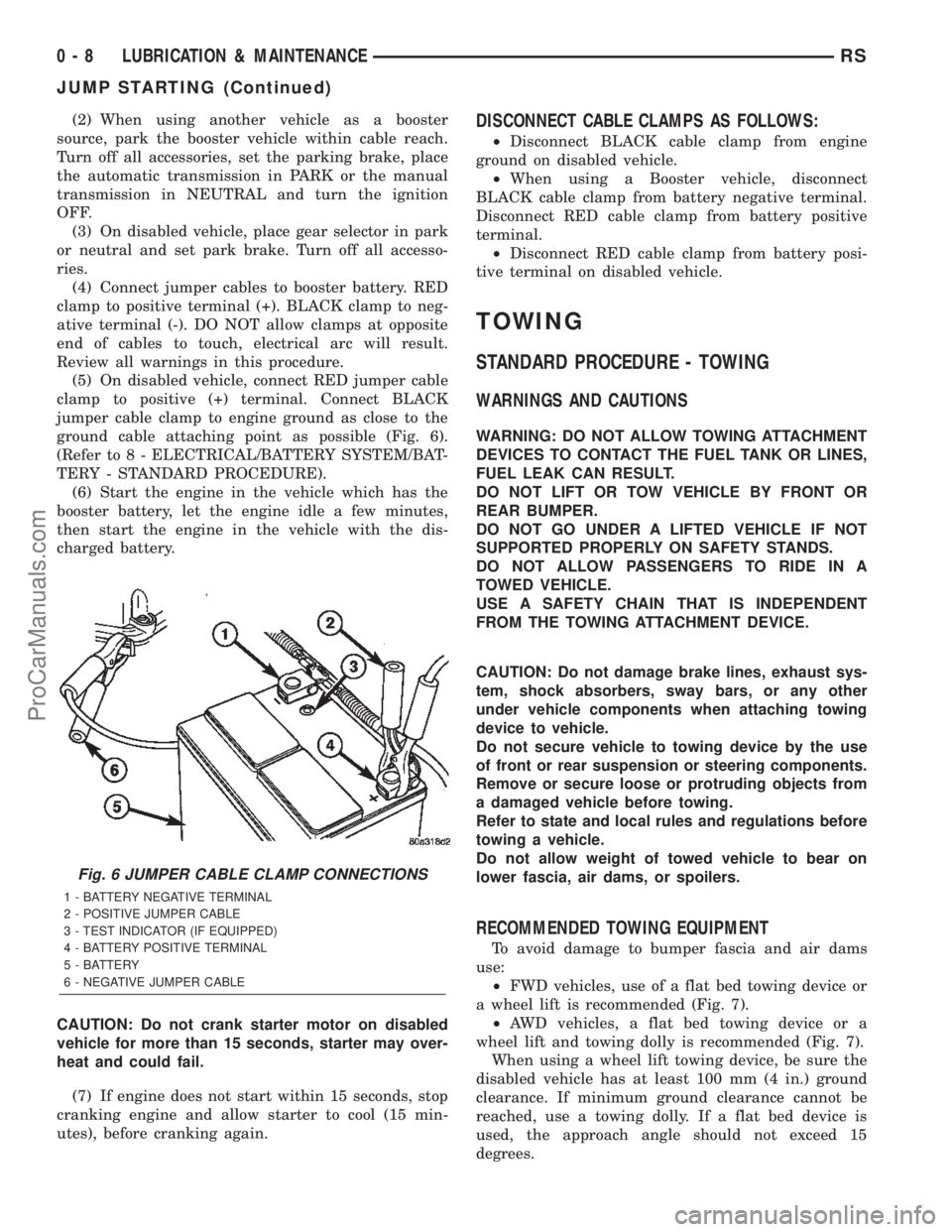
(5) On disabled vehicle, connect RED jumper cable
clamp to positive (+) terminal. Connect BLACK
jumper cable clamp to engine ground as close to the
ground cable attaching point as possible (Fig. 6).
(Refer to 8 - ELECTRICAL/BATTERY SYSTEM/BAT-
TERY - STANDARD PROCEDURE).
(6) Start the engine in the vehicle which has the
booster battery, let the engine idle a few minutes,
then start the engine in the vehicle with the dis-
charged battery.
CAUTION: Do not crank starter motor on disabled
vehicle for more than 15 seconds, starter may over-
heat and could fail.
(7) If engine does not start within 15 seconds, stop
cranking engine and allow starter to cool (15 min-
utes), before cranking again.DISCONNECT CABLE CLAMPS AS FOLLOWS:
²Disconnect BLACK cable clamp from engine
ground on disabled vehicle.
²When using a Booster vehicle, disconnect
BLACK cable clamp from battery negative terminal.
Disconnect RED cable clamp from battery positive
terminal.
²Disconnect RED cable clamp from battery posi-
tive terminal on disabled vehicle.
TOWING
STANDARD PROCEDURE - TOWING
WARNINGS AND CAUTIONS
WARNING: DO NOT ALLOW TOWING ATTACHMENT
DEVICES TO CONTACT THE FUEL TANK OR LINES,
FUEL LEAK CAN RESULT.
DO NOT LIFT OR TOW VEHICLE BY FRONT OR
REAR BUMPER.
DO NOT GO UNDER A LIFTED VEHICLE IF NOT
SUPPORTED PROPERLY ON SAFETY STANDS.
DO NOT ALLOW PASSENGERS TO RIDE IN A
TOWED VEHICLE.
USE A SAFETY CHAIN THAT IS INDEPENDENT
FROM THE TOWING ATTACHMENT DEVICE.
CAUTION: Do not damage brake lines, exhaust sys-
tem, shock absorbers, sway bars, or any other
under vehicle components when attaching towing
device to vehicle.
Do not secure vehicle to towing device by the use
of front or rear suspension or steering components.
Remove or secure loose or protruding objects from
a damaged vehicle before towing.
Refer to state and local rules and regulations before
towing a vehicle.
Do not allow weight of towed vehicle to bear on
lower fascia, air dams, or spoilers.
RECOMMENDED TOWING EQUIPMENT
To avoid damage to bumper fascia and air dams
use:
²FWD vehicles, use of a flat bed towing device or
a wheel lift is recommended (Fig. 7).
²AWD vehicles, a flat bed towing device or a
wheel lift and towing dolly is recommended (Fig. 7).
When using a wheel lift towing device, be sure the
disabled vehicle has at least 100 mm (4 in.) ground
clearance. If minimum ground clearance cannot be
reached, use a towing dolly. If a flat bed device is
used, the approach angle should not exceed 15
degrees.
Fig. 6 JUMPER CABLE CLAMP CONNECTIONS
1 - BATTERY NEGATIVE TERMINAL
2 - POSITIVE JUMPER CABLE
3 - TEST INDICATOR (IF EQUIPPED)
4 - BATTERY POSITIVE TERMINAL
5 - BATTERY
6 - NEGATIVE JUMPER CABLE
0 - 8 LUBRICATION & MAINTENANCERS
JUMP STARTING (Continued)
ProCarManuals.com
Page 251 of 2399
OPERATION
OPERATION - COOLING SYSTEM
The engine cooling systems primary purpose is to
maintain engine temperature in a range that will
provide satisfactory engine performance and emission
levels under all expected driving conditions. It also
provides hot water (coolant) for heater performance
and cooling for automatic transmission oil. It does
this by transferring heat from engine metal to cool-
ant, moving this heated coolant to the radiator, and
then transferring this heat to the ambient air.
²When engine is cold: thermostat is closed, cool-
ing system has no flow through the radiator. The
coolant bypass flows through the engine only.
²When engine is warm: thermostat is open, cool-
ing system has bypass flow and coolant flow through
radiator.
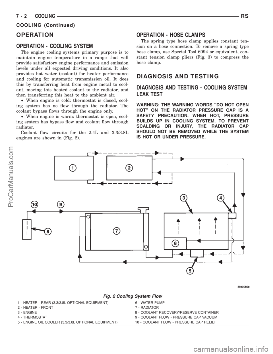
Coolant flow circuits for the 2.4L and 3.3/3.8L
engines are shown in (Fig. 2).
OPERATION - HOSE CLAMPS
The spring type hose clamp applies constant ten-
sion on a hose connection. To remove a spring type
hose clamp, use Special Tool 6094 or equivalent, con-
stant tension clamp pliers (Fig. 3) to compress the
hose clamp.
DIAGNOSIS AND TESTING
DIAGNOSIS AND TESTING - COOLING SYSTEM
LEAK TEST
WARNING: THE WARNING WORDS ªDO NOT OPEN
HOTº ON THE RADIATOR PRESSURE CAP IS A
SAFETY PRECAUTION. WHEN HOT, PRESSURE
BUILDS UP IN COOLING SYSTEM. TO PREVENT
SCALDING OR INJURY, THE RADIATOR CAP
SHOULD NOT BE REMOVED WHILE THE SYSTEM
IS HOT OR UNDER PRESSURE.
Fig. 2 Cooling System Flow
1 - HEATER - REAR (3.3/3.8L OPTIONAL EQUIPMENT) 6 - WATER PUMP
2 - HEATER - FRONT 7 - RADIATOR
3 - ENGINE 8 - COOLANT RECOVERY/RESERVE CONTAINER
4 - THERMOSTAT 9 - COOLANT FLOW - PRESSURE CAP VACUUM
5 - ENGINE OIL COOLER (3.3/3.8L OPTIONAL EQUIPMENT) 10 - COOLANT FLOW - PRESSURE CAP RELIEF
7 - 2 COOLINGRS
COOLING (Continued)
ProCarManuals.com
Page 252 of 2399
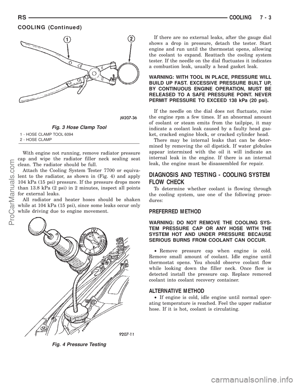
With engine not running, remove radiator pressure
cap and wipe the radiator filler neck sealing seat
clean. The radiator should be full.
Attach the Cooling System Tester 7700 or equiva-
lent to the radiator, as shown in (Fig. 4) and apply
104 kPa (15 psi) pressure. If the pressure drops more
than 13.8 kPa (2 psi) in 2 minutes, inspect all points
for external leaks.
All radiator and heater hoses should be shaken
while at 104 kPa (15 psi), since some leaks occur only
while driving due to engine movement.If there are no external leaks, after the gauge dial
shows a drop in pressure, detach the tester. Start
engine and run until the thermostat opens, allowing
the coolant to expand. Reattach the cooling system
tester. If the needle on the dial fluctuates it indicates
a combustion leak, usually a head gasket leak.
WARNING: WITH TOOL IN PLACE, PRESSURE WILL
BUILD UP FAST. EXCESSIVE PRESSURE BUILT UP,
BY CONTINUOUS ENGINE OPERATION, MUST BE
RELEASED TO A SAFE PRESSURE POINT. NEVER
PERMIT PRESSURE TO EXCEED 138 kPa (20 psi).
If the needle on the dial does not fluctuate, raise
the engine rpm a few times. If an abnormal amount
of coolant or steam emits from the tailpipe, it may
indicate a coolant leak caused by a faulty head gas-
ket, cracked engine block, or cracked cylinder head.
There may be internal leaks that can be deter-
mined by removing the oil dipstick. If water globules
appear intermixed with the oil it will indicate an
internal leak in the engine. If there is an internal
leak, the engine must be disassembled for repair.
DIAGNOSIS AND TESTING - COOLING SYSTEM
FLOW CHECK
To determine whether coolant is flowing through
the cooling system, use one of the following proce-
dures:
PREFERRED METHOD
WARNING: DO NOT REMOVE THE COOLING SYS-
TEM PRESSURE CAP OR ANY HOSE WITH THE
SYSTEM HOT AND UNDER PRESSURE BECAUSE
SERIOUS BURNS FROM COOLANT CAN OCCUR.
²Remove pressure cap when engine is cold.
Remove small amount of coolant. Idle engine until
thermostat opens. You should observe coolant flow
while looking down the filler neck. Once flow is
detected install the pressure cap. Replace removed
coolant into coolant recovery container.
ALTERNATIVE METHOD
²If engine is cold, idle engine until normal oper-
ating temperature is reached. Feel the upper radiator
hose. If it is hot, coolant is circulating.
Fig. 3 Hose Clamp Tool
1 - HOSE CLAMP TOOL 6094
2 - HOSE CLAMP
Fig. 4 Pressure Testing
RSCOOLING7-3
COOLING (Continued)
ProCarManuals.com
Page 290 of 2399
COOLING 2.5L TURBO DIESEL
TABLE OF CONTENTS
page page
COOLING 2.5L TURBO DIESEL
DESCRIPTION - COOLING SYSTEM.........1
DIAGNOSIS AND TESTING
DIAGNOSIS AND TESTING - COOLING
SYSTEM.............................1
DIAGNOSIS AND TESTING - COOLING
SYSTEM LEAK TEST....................6
DIAGNOSIS AND TESTING - COOLING
SYSTEM FLOW CHECK.................7
DIAGNOSIS AND TESTING - COOLING
SYSTEM AERATION....................7CLEANING.............................7
INSPECTION...........................7
SPECIFICATIONS
SPECIFICATIONS - TORQUE.............8
SPECIFICATIONS - COOLING SYSTEM
CAPACITY............................8
ACCESSORY DRIVE.......................9
ENGINE...............................14
COOLING 2.5L TURBO DIESEL
DESCRIPTION - COOLING SYSTEM
The cooling system regulates engine operating tem-
perature. It allows the engine to reach normal oper-
ating temperature as quickly as possible, maintains
normal operating temperature and prevents over-
heating.
The cooling system also provides a means of heat-
ing the passenger compartment. The cooling system
is pressurized and uses a centrifugal water pump to
circulate coolant throughout the system. A separate
and remotely mounted, pressurized coolant tank
using a pressure/vent cap is used.
COOLING SYSTEM COMPONENTS
The cooling system consists of:
²Charge Air Cooler
²Electric Cooling Fans
²A aluminum-core radiator with plastic side
tanks
²A separate pressurized coolant tank
²A pressure/vent cap on the coolant tank
²Fan shroud
²Thermostat
²Coolant
²Low coolant warning lamp
²Coolant temperature gauge
²Water pump
²Hoses and hose clamps
DIAGNOSIS AND TESTING
DIAGNOSIS AND TESTING - COOLING SYSTEM
Establish what driving conditions caused the com-
plaint. Abnormal loads on the cooling system such as
the following may be the cause:
(1) PROLONGED IDLE, VERY HIGH AMBIENT
TEMPERATURE, SLIGHT TAIL WIND AT IDLE,
SLOW TRAFFIC, TRAFFIC JAMS, HIGH SPEED
OR STEEP GRADES.
Driving techniques that avoid overheating are:
²Idle with A/C off when temperature gauge is at
end of normal range.
²Increasing engine speed for more air flow is rec-
ommended.
(2) TRAILER TOWING:
Consult Trailer Towing section of owners manual.
Do not exceed limits.
(3) RECENT SERVICE OR ACCIDENT REPAIR:
Determine if any recent service has been per-
formed on vehicle that may effect cooling system.
This may be:
²Engine adjustments (incorrect timing)
²Slipping engine accessory drive belt
²Brakes (possibly dragging)
²Changed parts (incorrect water pump)
²Reconditioned radiator or cooling system refill-
ing (possibly under filled or air trapped in system).
NOTE: If investigation reveals none of the previous
items as a cause for an engine overheating com-
plaint, refer to following Cooling System Diagnosis
charts.
These charts are to be used as a quick-reference
only.
RGCOOLING 2.5L TURBO DIESEL7a-1
ProCarManuals.com
Page 296 of 2399
DIAGNOSIS AND TESTING - COOLING SYSTEM
FLOW CHECK
To determine whether coolant is flowing through
the cooling system, use the following procedures:
(1) If engine is cold, idle engine until normal oper-
ating temperature is reached. Then feel the upper
radiator hose. If it is hot, coolant is circulating.
WARNING: DO NOT REMOVE THE COOLING SYS-
TEM PRESSURE CAP WITH THE SYSTEM HOT AND
UNDER PRESSURE BECAUSE SERIOUS BURNS
FROM COOLANT CAN OCCUR.(2) Remove pressure/vent cap when engine is cold,
idle engine until thermostat opens, you should
observe coolant flow while looking down in the cool-
ant recovery pressure container. Once flow is
detected install the pressure/vent cap.
DIAGNOSIS AND TESTING - COOLING SYSTEM
AERATION
Low coolant level in a cross flow radiator will
equalize in both tanks with engine off. With engine
at running and at operating temperature, the high
pressure inlet tank runs full and the low pressure
outlet tank drops, resulting in cooling system aera-
tion. Aeration will draw air into the water pump
resulting in the following:
²High reading shown on the temperature gauge.
²Loss of coolant flow through the heater core.
²Corrosion in the cooling system.
²Water pump seal may run dry, increasing the
risk of premature seal failure.
²Combustion gas leaks into the coolant can also
cause the above problems.
CLEANING
Drain cooling system and refill with clean water.
Refer to procedures in this section. Run engine with
pressure/vent cap installed until upper radiator hose
is hot. Stop engine and drain water from system. If
water is dirty; fill, run, and drain system again, until
water runs clear.
INSPECTION
After performing a cleaning/flush procedure,
inspect all hoses, clamps and connections for deterio-
ration and leaks. Inspect radiator and heater core for
leaks.
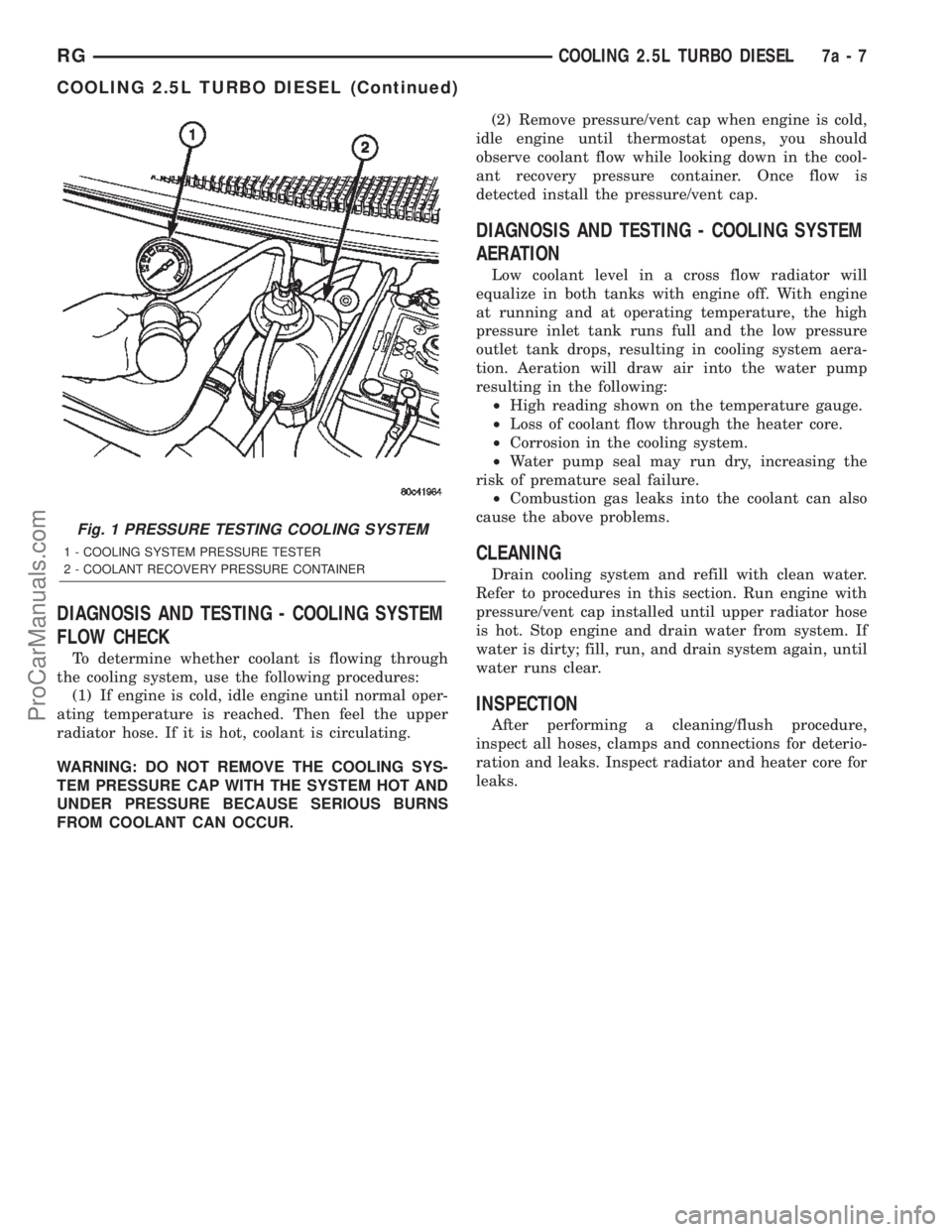
Fig. 1 PRESSURE TESTING COOLING SYSTEM
1 - COOLING SYSTEM PRESSURE TESTER
2 - COOLANT RECOVERY PRESSURE CONTAINER
RGCOOLING 2.5L TURBO DIESEL7a-7
COOLING 2.5L TURBO DIESEL (Continued)
ProCarManuals.com
Page 334 of 2399
CHIME/BUZZER
TABLE OF CONTENTS
page page
CHIME/BUZZER
DESCRIPTION..........................1
OPERATION............................1
WARNING.............................1
DIAGNOSIS AND TESTING
DIAGNOSIS AND TESTING - CHIME
SYSTEM.............................1
DIAGNOSIS AND TESTING - DOME LAMP
ON CHIME............................2
DIAGNOSIS AND TESTING - ENGINE
TEMPERATURE CRITICAL CHIME..........2
DIAGNOSIS AND TESTING - EXTERIOR
LAMPS ON CHIME.....................2
DIAGNOSIS AND TESTING - KEY-IN
IGNITION CHIME.......................2DIAGNOSIS AND TESTING - LOW OIL
PRESSURE CHIME.....................3
DIAGNOSIS AND TESTING - SEAT BELT
CHIME...............................3
DIAGNOSIS AND TESTING - SEAT BELT
LAMP...............................3
DIAGNOSIS AND TESTING - TIRE
PRESSURE MONITOR..................3
DIAGNOSIS AND TESTING - TURN SIGNAL
ON CHIME............................3
DIAGNOSIS AND TESTING - WARNING
LAMP ANNOUNCEMENT CHIME...........4
CHIME/BUZZER
DESCRIPTION
The chime/buzzer system provides the driver with
warning chimes for:
²Seat Belt
²Exterior Lamps ON
²Key-In Ignition
²Engine Temperature Critical
²Turn Signals ON
²Dome Lamp ON
²Low Oil Pressure
²High Speed Warning
²Warning Lamp Announcement
²Key-In Accessory
²Low/High Tire Pressure
²Service Tire Pressure Monitor (TPM)
HIGH SPEED WARNING - EXPORT
The chime will sound, acting as a warning to the
driver that the vehicle speed has exceeded 120 3
kph (75 2 mph).
OPERATION
The Chime/Buzzer Warning System is diagnosed
using a DRB llltscan tool. Refer to the proper Body
Diagnostic Procedures Manual.
HIGH SPEED WARNING - EXPORT
When the vehicle speed sensor sees 120 3kph
(75 2 mph), it sends a PCI data bus message to the
Body Control Module (BCM). The BCM then turns onthe chime to let the driver know that the vehicle has
reached a speed greater than 120 3kph(75 2
mph). This audible message will continue until the
vehicle is slowed below the predetermined speed.
WARNING
WARNING: ON VEHICLES EQUIPPED WITH AIR-
BAGS, DISABLE THE AIRBAG SYSTEM BEFORE
ATTEMPTING ANY STEERING WHEEL, STEERING
COLUMN, OR INSTRUMENT PANEL COMPONENT
DIAGNOSIS OR SERVICE. DISCONNECT AND ISO-
LATE THE BATTERY NEGATIVE (GROUND) CABLE,
THEN WAIT TWO MINUTES FOR THE AIRBAG SYS-
TEM CAPACITOR TO DISCHARGE BEFORE PER-
FORMING FURTHER DIAGNOSIS OR SERVICE. THIS
IS THE ONLY SURE WAY TO DISABLE THE AIRBAG
SYSTEM. FAILURE TO TAKE THE PROPER PRE-
CAUTIONS COULD RESULT IN ACCIDENTAL AIR-
BAG DEPLOYMENT AND POSSIBLE PERSONAL
INJURY.
DIAGNOSIS AND TESTING
DIAGNOSIS AND TESTING - CHIME SYSTEM
NO TONE WHEN IGNITION SWITCH IS TURNED ON
AND DRIVER'S SEAT BELT IS NOT BUCKLED.
(1) Using a DRB llltscan tool, actuate chime
(BCM actuates).
(2) Using a voltmeter, check for voltage:
RSCHIME/BUZZER8B-1
ProCarManuals.com
Page 335 of 2399
(a) BCM has two battery feeds at pin 1 and pin
5 of the 6±way connector.
(b) Pin 5 of the (BX2) 32 way connector of the
BCM for ignition feed.
(c) Check voltage (PX2) connector, pin 34 for 12v.
(d) If voltage OK, go to step Step 3
(e) If NO voltage repair as necessary. Refer to
the appropriate wiring information. The wiring
information includes wiring diagrams, proper wire
and connector repair procedures, further details on
wire harness routing and retention, as well as pin-
out and location views for the various wire harness
connectors, splices and grounds.
(3) Check driver's seat belt buckle switch input
(form ORC) for a closed circuit when not buckled. If
input not seen, look for open in wiring or switch. The
switch is grounded when belt is not buckled.
(4) Verify PCI data bus communication between
ORC and BCM.
NO FASTEN SEAT BELT LAMP WHEN IGNITION
SWITCH IS TURNED ON.
(1) Check for burned out lamp.
(2) Using a voltmeter check for voltage at the clus-
ter conncctor:
(a) Pin 2 of the mechanical instrument cluster
for battery feed.
(b) Pin 11 of the mechanical instrument cluster
for ignition voltage.
(3) Repair as necessary.
FASTEN SEAT BELT LAMP OR TONE CONTINUES
FOR MORE THAN 10 SECONDS AFTER SEAT
BELTS ARE FASTENED AND DRIVER'S DOOR IS
CLOSED.
Refer to the proper Body Diagnostic Procedures
manual.
NO TONE WHEN PARK OR HEADLAMPS ARE ON
AND DRIVER'S DOOR IS OPEN.
Make sure ignition is in lock position with the key
removed.
(1) Check the BCM DTC's and BCM sensors to
verify the door is open. Repair as necessary.
(2) Actuate Chime (BCM actuates).
(3) Inspect BCM connectors and wires for proper
connection.
(4) Measure with a voltmeter the voltage (12v) on
BCM connector (PX2) pin 34 with harness connected.
DIAGNOSIS AND TESTING - DOME LAMP ON
CHIME
The dome lamp on chime will warn the driver that
the dome lamps have been left on.When the ignition is OFF and the key is out of the
ignition:
²Driver's door OPEN (door ajar switch is closed to
ground) and
²Dome lamps are ON (dome lamp switch is closed
to ground),
The chime will sound continuously until the driv-
ers door is closed, dome lamps turned OFF or until
the battery protection time out of 15 minutes has
expired. Chime rate: 168 to 192 chimes per minute.
DIAGNOSIS AND TESTING - ENGINE
TEMPERATURE CRITICAL CHIME
The engine temperature critical chime will warn
the driver that the vehicle's engine is overheating.
While monitoring the coolant temperature, the Pow-
ertrain Control Module (PCM) will send on the PCI
data bus as engine temperature every 1.376 seconds
to the cluster. The MIC calculates engine tempera-
ture and determines if a warning should occur. This
feature is functional only with the Ignition Switch in
the Run/Start position.
When the engine temperature reaches 122ÉC
(252ÉF) the MIC requests a chime from the BCM and
the engine temperature lamp comes ON. The MIC
turns OFF the lamp when the engine temperature
reaches 117ÉC (242ÉF). The MIC will chime continu-
ously (request from the BCM). The chime will turn
OFF after four minutes or when the temperature
reaches 117ÉC (242ÉF), which ever occurs first.
DIAGNOSIS AND TESTING - EXTERIOR LAMPS
ON CHIME
The exterior lamp on chime will warn the driver
that the exterior lights have been left on.
With the ignition switch OFF/key out of ignition:
²Driver's door is open (door ajar switch is closed
to ground)
²Parking lamps or headlamps ON (parking lamp
switch is closed to ground)
The chime will sound until lights are turned OFF,
driver's door closed or until the battery protection
time out of 3 minutes has expired.
Chime rate: 168 to 192 chimes per minute.
To test the exterior lamps left on function:
²Turn ignition off
²Remove ignition key
²Turn exterior lamps on with driver's door open.
Chime should sound until lamps are turned off or
driver's door is closed.
DIAGNOSIS AND TESTING - KEY-IN IGNITION
CHIME
The key-in ignition chime will act as a warning to
the driver that the ignition key has been left in the
8B - 2 CHIME/BUZZERRS
CHIME/BUZZER (Continued)
ProCarManuals.com
Page 336 of 2399
ignition switch. This chime will operate for all igni-
tion positions except ON and START.
With the ignition switch in the OFF position
O N LY:
²Driver's door is open/ajar (door ajar switch is
closed to ground)
²Key is in the ignition switch (ignition is in the
LOCK position)
The chime will sound until one of the above condi-
tions is removed or until battery protection time out
(15 min.) has expired. Chime rate: 168 to 192 chimes
per minute.
To test the key-in ignition function, insert key into
the ignition and open drivers door. Do not turn igni-
tion ON. Chime should sound until key is removed
from ignition or drivers door is closed.
For diagnosis and testing of the Key-In chime for
other ignition positions, use the same testing proce-
dure as above but with the key in the accessory or
unlock position.
DIAGNOSIS AND TESTING - LOW OIL
PRESSURE CHIME
The low oil pressure chime will warn the driver
that the engine oil pressure is low. The oil pressure
switch will close to ground during a low oil pressure
condition. The oil pressure lamp will illuminate in
the message center. The PCM will monitor the oil
pressure switch and signal a low oil pressure condi-
tion. A continuous four minute warning chime will
sound and the oil pressure lamp will come ON when
the following conditions are met:
²Ignition on and engine not cranking
²Engine running at 420 to 480 rpm for 10 sec-
onds
²Oil pressure switch closed to ground for (1 sec-
ond minimum, 2 seconds maximum)
Chime rate: 168 to 192 chimes per minute.
DIAGNOSIS AND TESTING - SEAT BELT CHIME
The seat belt chime will sound for 4 to 8 seconds,
when the ignition is turned on and the driver's seat
belt is not buckled (seat belt switch is closed to
ground). This is a reminder to the driver to buckle
the seat belt. The seat belt lamp is controlled by the
ORC. The cluster will also bulb check the seat belt
warning lamp for 6 seconds. Buckling the driver's
seat belt before the time out has expired will cause
the chime to stop immediately. Chime rate: 38 to 62
chimes per minute but the lamp will remain on until
6 seconds have expired.
To test the seat belt warning system, the ignition
switch must be in the OFF position for 1 minute
before starting the test. Turn the ignition switch to
the on position with the driver's seat belt not buck-led. The seat belt warning lamp should light and the
chime should sound 4 to 8 seconds.
DIAGNOSIS AND TESTING - SEAT BELT LAMP
The seat belt lamp in the instrument cluster sig-
nals the vehicle passengers to fasten their seat belts.
The seat belt lamp is illuminated directly by the
instrument cluster for 6 seconds after the instrument
cluster receives the message from the ORC. The seat
belt lamp is therefore illuminated for 6 seconds
whenever the ignition switch is moved to run/start
position.
(1) While ignition is off, the seat belt lamp will not
be illuminated.
(2) The ignition power feed status will be updated
every 250 milliseconds or on change.
(3) This lamp will be checked by the instrument
cluster for 6 seconds with every run/start cycle of the
ignition switch.
DIAGNOSIS AND TESTING - TIRE PRESSURE
MONITOR
The Tire Pressure Warning chime, as well as the
information being displayed in the EVIC, will act as
a warning to the driver that a tire has either Low or
High pressure, or if there is a need to service the
Tire Pressure Monitor System. With the ignition
switch in the ON position and the ªLow Pressure/
High Pressureº or ªService the TPM Systemº dis-
played on the EVIC display, a single chime will
sound.
DIAGNOSIS AND TESTING - TURN SIGNAL ON
CHIME
The turn signal on chime will warn the driver that
the turn signals have been left on. When the body
control module receives a turn signal input for 1.0
mile, vehicle speed is greater than 24 km/h (15 mph),
the chime will sound continuously until the turn sig-
nal is turned OFF. If vehicle speed drops below 24
km/h (15 mph) prior to the warning being activated,
the accumulated distance traveled will be reset. The
turn signal chime is not activated when the emer-
gency flashers are turned on. Chime rate: 50 12
chimes per minute.
For the turn signal warning system to operate:
²Must have input from either the right or left
turn signal lamps. Creates a voltage change between
0 and battery voltage.
²The vehicle speed sensor sends a message to the
Powertrain Control Module that vehicle has exceeded
24 km/h (15 mph) for 1.0 mile).
²When the above two conditions are met, the
chime will sound. The chime will stop when no fur-
ther voltage change is detected.
RSCHIME/BUZZER8B-3
CHIME/BUZZER (Continued)
ProCarManuals.com