front lighting CHRYSLER VOYAGER 2002 User Guide
[x] Cancel search | Manufacturer: CHRYSLER, Model Year: 2002, Model line: VOYAGER, Model: CHRYSLER VOYAGER 2002Pages: 2399, PDF Size: 57.96 MB
Page 513 of 2399
(4) Install the headlamp unit.
(5) Connect the battery negative cable.
HEADLAMP
DIAGNOSIS AND TESTING - HEADLAMP
When a vehicle experiences problems with the
headlamp system, verify the condition of the battery
connections, fuses, charging system, headlamp bulbs,
wire connectors, relay, high beam switch, dimmer
switch, and headlamp switch. Refer to the appropri-
ate wiring information.
Each vehicle is equipped with various lamp assem-
blies. A good ground is necessary for proper lighting
operation. Grounding is provided by the lamp socket
when it comes in contact with the metal body, or
through a separate ground wire.
When changing lamp bulbs check the socket for
corrosion. If corrosion is present, clean it with a wire
brush.
When it is necessary to remove components to ser-
vice another, it should not be necessary to apply
excessive force or bend a component to remove it.
Before damaging a trim component, verify hidden
fasteners or captured edges are not holding the com-
ponent in place.
HEADLAMP DIAGNOSIS
CONDITION POSSIBLE CAUSES CORRECTION
HEADLAMPS ARE DIM
WITH ENGINE IDLING
OR IGNITION TURNED
OFF.1. Loose or corroded battery
cables.1. Clean and secure battery cable clamps and
posts.
2. Loose or worn generator drive
belt.2. Adjust or replace generator drive belt.
3. Charging system output too low. 3. Test and repair charging system, refer to
Electrical, Charging
4. Battery has insufficient charge. 4. Test battery state-of-charge, refer to
Electrical, Battery System.
5. Battery is sulfated or shorted. 5. Load test battery, refer to Electrical, Battery
System.
6. Poor lighting circuit Z343/Z344-
ground.6. Test for voltage drop across Z343/Z344-
ground locations, refer to Electrical, Wiring
Diagram Information.
HEADLAMP BULBS
BURN OUT
FREQUENTLY.1. Integrated Power Module (IPM)
not controlling voltage.1. Test and repair Integrated Power Module.
2. Loose or corroded terminals or
splices in circuit.2. Inspect and repair all connectors and splices.
Refer to Electrical, Wiring Information.
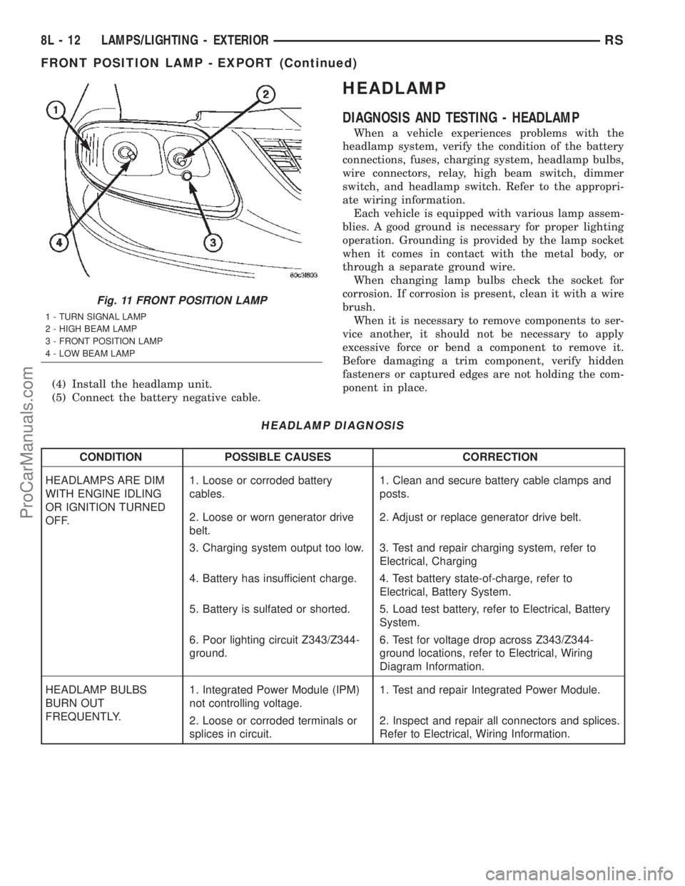
Fig. 11 FRONT POSITION LAMP
1 - TURN SIGNAL LAMP
2 - HIGH BEAM LAMP
3 - FRONT POSITION LAMP
4 - LOW BEAM LAMP
8L - 12 LAMPS/LIGHTING - EXTERIORRS
FRONT POSITION LAMP - EXPORT (Continued)
ProCarManuals.com
Page 517 of 2399
HEADLAMP LEVELING
SWITCH - EXPORT
DESCRIPTION
Some vehicles are equipped with a remote head-
lamp leveling system. This system allows the driver
to adjust the vertical headlamp aim from the interior
of the vehicle to compensate for passenger or cargo
load.
The headlamp leveling switch is located next to the
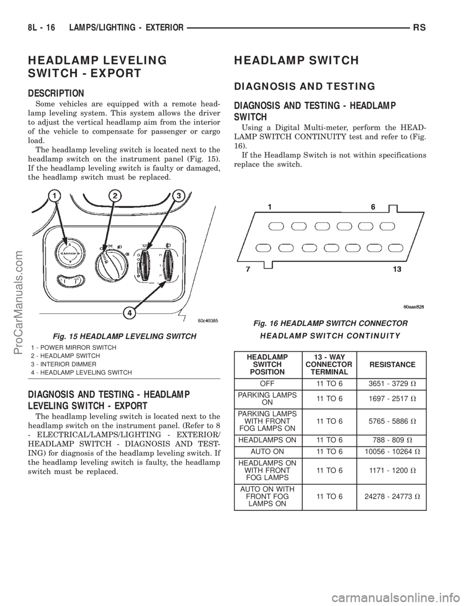
headlamp switch on the instrument panel (Fig. 15).
If the headlamp leveling switch is faulty or damaged,
the headlamp switch must be replaced.
DIAGNOSIS AND TESTING - HEADLAMP
LEVELING SWITCH - EXPORT
The headlamp leveling switch is located next to the
headlamp switch on the instrument panel. (Refer to 8
- ELECTRICAL/LAMPS/LIGHTING - EXTERIOR/
HEADLAMP SWITCH - DIAGNOSIS AND TEST-
ING) for diagnosis of the headlamp leveling switch. If
the headlamp leveling switch is faulty, the headlamp
switch must be replaced.
HEADLAMP SWITCH
DIAGNOSIS AND TESTING
DIAGNOSIS AND TESTING - HEADLAMP
SWITCH
Using a Digital Multi-meter, perform the HEAD-
LAMP SWITCH CONTINUITY test and refer to (Fig.
16).
If the Headlamp Switch is not within specifications
replace the switch.
HEADLAMP SWITCH CONTINUITY
HEADLAMP
SWITCH
POSITION13-WAY
CONNECTOR
TERMINALRESISTANCE
OFF 11 TO 6 3651 - 3729V
PARKING LAMPS
ON11 TO 6 1697 - 2517V
PARKING LAMPS
WITH FRONT
FOG LAMPS ON11 TO 6 5765 - 5886V
HEADLAMPS ON 11 TO 6 788 - 809V
AUTO ON 11 TO 6 10056 - 10264V
HEADLAMPS ON
WITH FRONT
FOG LAMPS11 TO 6 1171 - 1200V
AUTO ON WITH
FRONT FOG
LAMPS ON11 TO 6 24278 - 24773V
Fig. 15 HEADLAMP LEVELING SWITCH
1 - POWER MIRROR SWITCH
2 - HEADLAMP SWITCH
3 - INTERIOR DIMMER
4 - HEADLAMP LEVELING SWITCH
Fig. 16 HEADLAMP SWITCH CONNECTOR
8L - 16 LAMPS/LIGHTING - EXTERIORRS
ProCarManuals.com
Page 518 of 2399
DIMMER
POSITION13-WAY
CONNECTOR
TERMINALRESISTANCE
DOME 12 TO 6 15568 - 23357V
PARADE 12 TO 6 5168 - 7757V
DIM HIGH 12 TO 6 2288 - 3437V
DIM LOW 12 TO 6 688 - 1037V
OFF 12 TO 6 240 - 365V
DIAGNOSIS AND TESTING - HEADLAMP
SWITCH - EXPORT
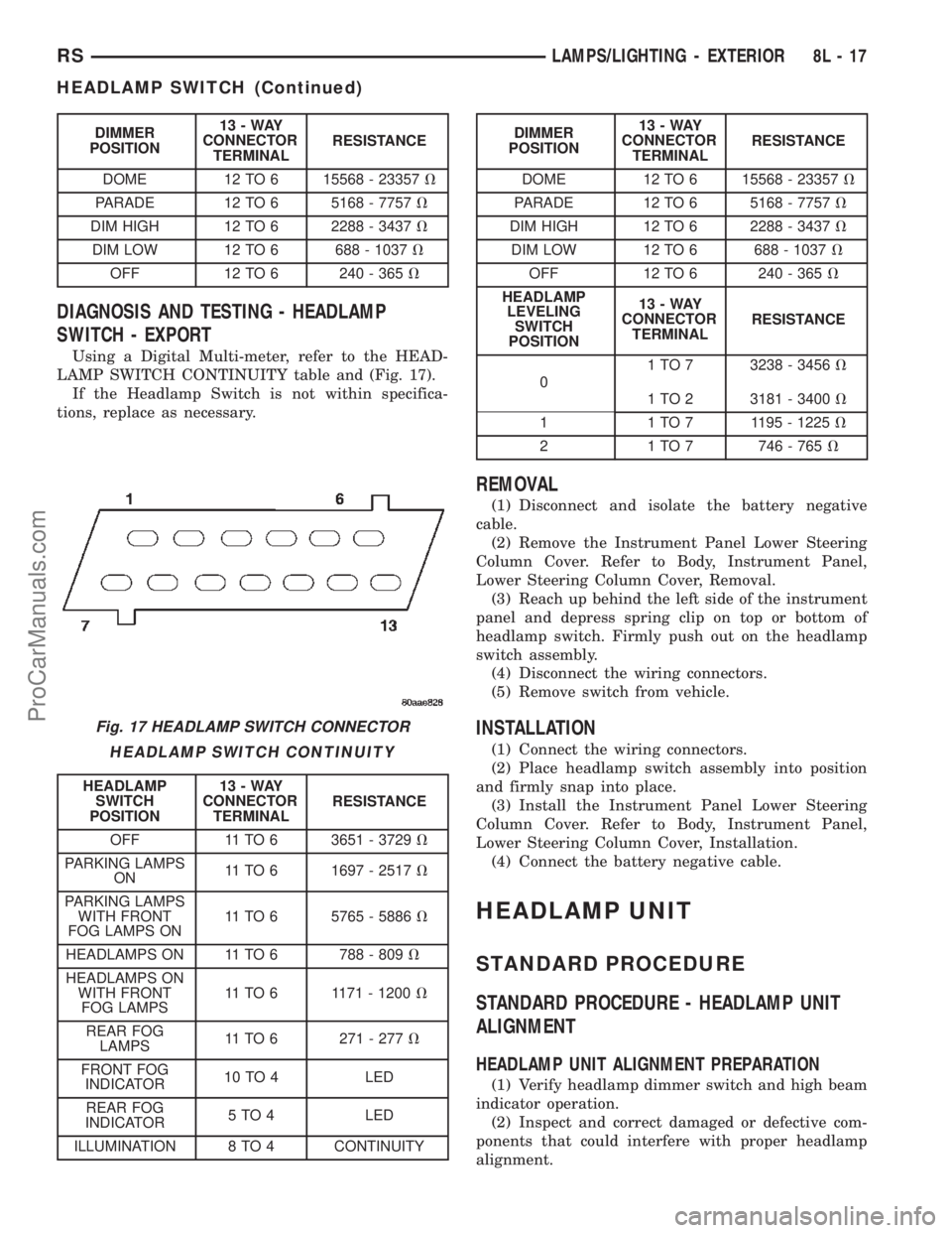
Using a Digital Multi-meter, refer to the HEAD-
LAMP SWITCH CONTINUITY table and (Fig. 17).
If the Headlamp Switch is not within specifica-
tions, replace as necessary.
HEADLAMP SWITCH CONTINUITY
HEADLAMP
SWITCH
POSITION13-WAY
CONNECTOR
TERMINALRESISTANCE
OFF 11 TO 6 3651 - 3729V
PARKING LAMPS
ON11 TO 6 1697 - 2517V
PARKING LAMPS
WITH FRONT
FOG LAMPS ON11 TO 6 5765 - 5886V
HEADLAMPS ON 11 TO 6 788 - 809V
HEADLAMPS ON
WITH FRONT
FOG LAMPS11 TO 6 1171 - 1200V
REAR FOG
LAMPS11 TO 6 271 - 277V
FRONT FOG
INDICATOR10 TO 4 LED
REAR FOG
INDICATOR5 TO 4 LED
ILLUMINATION 8 TO 4 CONTINUITY
DIMMER
POSITION13-WAY
CONNECTOR
TERMINALRESISTANCE
DOME 12 TO 6 15568 - 23357V
PARADE 12 TO 6 5168 - 7757V
DIM HIGH 12 TO 6 2288 - 3437V
DIM LOW 12 TO 6 688 - 1037V
OFF 12 TO 6 240 - 365V
HEADLAMP
LEVELING
SWITCH
POSITION13-WAY
CONNECTOR
TERMINALRESISTANCE
01 TO 7 3238 - 3456V
1 TO 2 3181 - 3400V
1 1 TO 7 1195 - 1225V
2 1 TO 7 746 - 765V
REMOVAL
(1) Disconnect and isolate the battery negative
cable.
(2) Remove the Instrument Panel Lower Steering
Column Cover. Refer to Body, Instrument Panel,
Lower Steering Column Cover, Removal.
(3) Reach up behind the left side of the instrument
panel and depress spring clip on top or bottom of
headlamp switch. Firmly push out on the headlamp
switch assembly.
(4) Disconnect the wiring connectors.
(5) Remove switch from vehicle.
INSTALLATION
(1) Connect the wiring connectors.
(2) Place headlamp switch assembly into position
and firmly snap into place.
(3) Install the Instrument Panel Lower Steering
Column Cover. Refer to Body, Instrument Panel,
Lower Steering Column Cover, Installation.
(4) Connect the battery negative cable.
HEADLAMP UNIT
STANDARD PROCEDURE
STANDARD PROCEDURE - HEADLAMP UNIT
ALIGNMENT
HEADLAMP UNIT ALIGNMENT PREPARATION
(1) Verify headlamp dimmer switch and high beam
indicator operation.
(2) Inspect and correct damaged or defective com-
ponents that could interfere with proper headlamp
alignment.
Fig. 17 HEADLAMP SWITCH CONNECTOR
RSLAMPS/LIGHTING - EXTERIOR8L-17
HEADLAMP SWITCH (Continued)
ProCarManuals.com
Page 519 of 2399
(3) Verify proper tire inflation.
(4) Clean headlamp lenses.
(5) Verify that luggage area is loaded as the vehi-
cle is routinely used.
(6) Fuel tank should be FULL. Add 2.94 kg (6.5
lbs.) of weight over the fuel tank for each estimated
gallon of missing fuel.
ALIGNMENT SCREEN PREPARATION
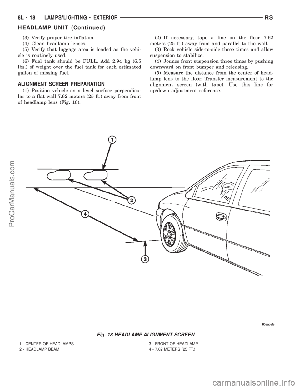
(1) Position vehicle on a level surface perpendicu-
lar to a flat wall 7.62 meters (25 ft.) away from front
of headlamp lens (Fig. 18).(2) If necessary, tape a line on the floor 7.62
meters (25 ft.) away from and parallel to the wall.
(3) Rock vehicle side-to-side three times and allow
suspension to stabilize.
(4) Jounce front suspension three times by pushing
downward on front bumper and releasing.
(5) Measure the distance from the center of head-
lamp lens to the floor. Transfer measurement to the
alignment screen (with tape). Use this line for
up/down adjustment reference.
Fig. 18 HEADLAMP ALIGNMENT SCREEN
1 - CENTER OF HEADLAMPS 3 - FRONT OF HEADLAMP
2 - HEADLAMP BEAM 4 - 7.62 METERS (25 FT.)
8L - 18 LAMPS/LIGHTING - EXTERIORRS
HEADLAMP UNIT (Continued)
ProCarManuals.com
Page 520 of 2399
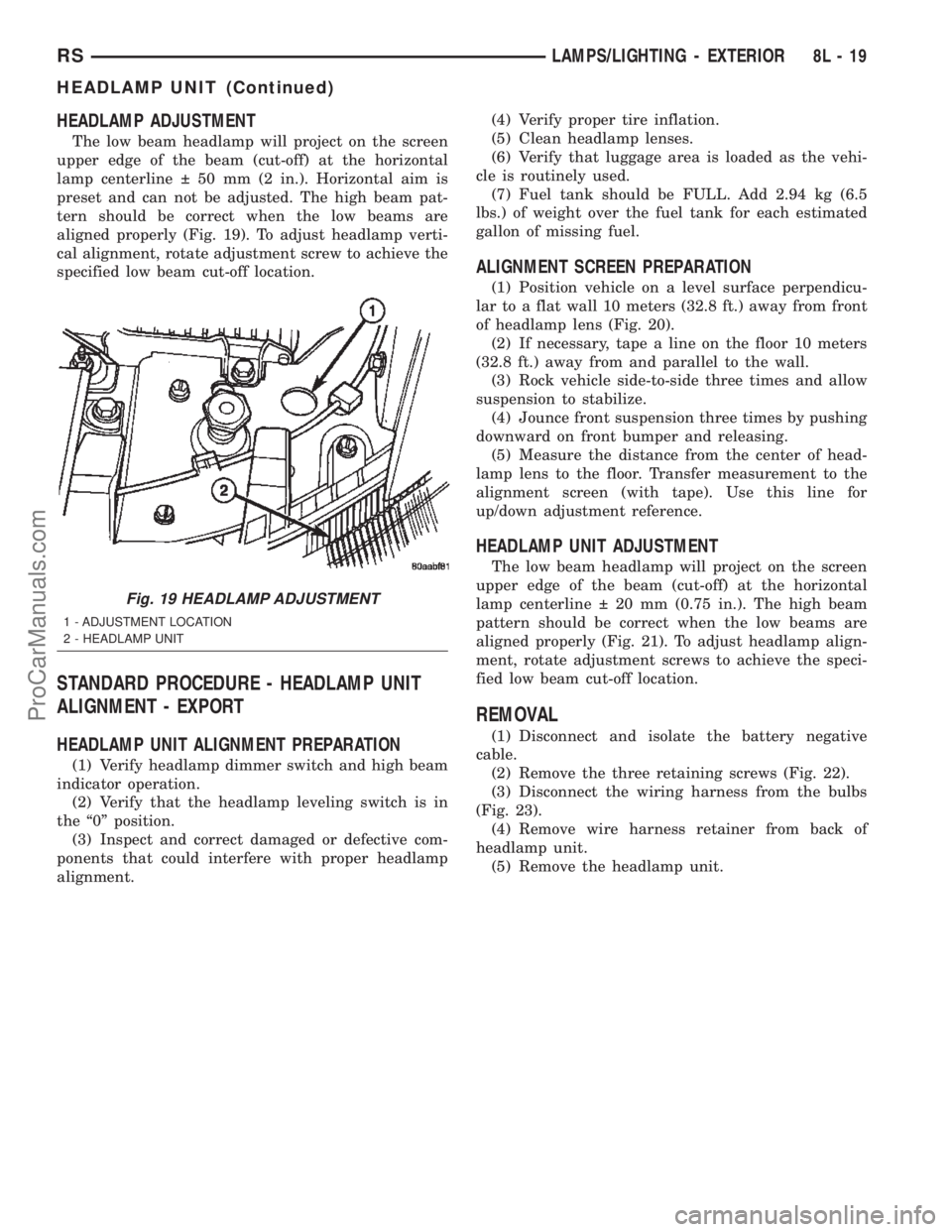
HEADLAMP ADJUSTMENT
The low beam headlamp will project on the screen
upper edge of the beam (cut-off) at the horizontal
lamp centerline 50 mm (2 in.). Horizontal aim is
preset and can not be adjusted. The high beam pat-
tern should be correct when the low beams are
aligned properly (Fig. 19). To adjust headlamp verti-
cal alignment, rotate adjustment screw to achieve the
specified low beam cut-off location.
STANDARD PROCEDURE - HEADLAMP UNIT
ALIGNMENT - EXPORT
HEADLAMP UNIT ALIGNMENT PREPARATION
(1) Verify headlamp dimmer switch and high beam
indicator operation.
(2) Verify that the headlamp leveling switch is in
the ª0º position.
(3) Inspect and correct damaged or defective com-
ponents that could interfere with proper headlamp
alignment.(4) Verify proper tire inflation.
(5) Clean headlamp lenses.
(6) Verify that luggage area is loaded as the vehi-
cle is routinely used.
(7) Fuel tank should be FULL. Add 2.94 kg (6.5
lbs.) of weight over the fuel tank for each estimated
gallon of missing fuel.
ALIGNMENT SCREEN PREPARATION
(1) Position vehicle on a level surface perpendicu-
lar to a flat wall 10 meters (32.8 ft.) away from front
of headlamp lens (Fig. 20).
(2) If necessary, tape a line on the floor 10 meters
(32.8 ft.) away from and parallel to the wall.
(3) Rock vehicle side-to-side three times and allow
suspension to stabilize.
(4) Jounce front suspension three times by pushing
downward on front bumper and releasing.
(5) Measure the distance from the center of head-
lamp lens to the floor. Transfer measurement to the
alignment screen (with tape). Use this line for
up/down adjustment reference.
HEADLAMP UNIT ADJUSTMENT
The low beam headlamp will project on the screen
upper edge of the beam (cut-off) at the horizontal
lamp centerline 20 mm (0.75 in.). The high beam
pattern should be correct when the low beams are
aligned properly (Fig. 21). To adjust headlamp align-
ment, rotate adjustment screws to achieve the speci-
fied low beam cut-off location.
REMOVAL
(1) Disconnect and isolate the battery negative
cable.
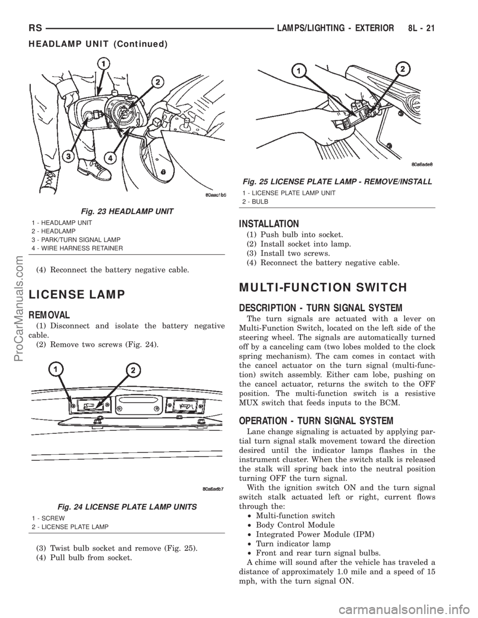
(2) Remove the three retaining screws (Fig. 22).
(3) Disconnect the wiring harness from the bulbs
(Fig. 23).
(4) Remove wire harness retainer from back of
headlamp unit.
(5) Remove the headlamp unit.
Fig. 19 HEADLAMP ADJUSTMENT
1 - ADJUSTMENT LOCATION
2 - HEADLAMP UNIT
RSLAMPS/LIGHTING - EXTERIOR8L-19
HEADLAMP UNIT (Continued)
ProCarManuals.com
Page 521 of 2399

INSTALLATION
(1) Reconnect wire harness to the bulbs.
(2) Install wire harness retainer to headlamp unit.
(3) Install the three retaining screws.
Fig. 20 HEADLAMP UNIT ALIGNMENT SCREEN - EXPORT
1 - CENTER OF VEHICLE 5 - 10 METERS (32.8 FT.)
2 - CENTER OF HEADLAMPS 6 - HORIZONTAL CUT-OFF LINE
3 - 15É CUT-OFF LINE 7 - 110 mm (4.3 in.)
4 - FRONT OF HEADLAMP
Fig. 21 HEADLAMP UNIT ADJUSTMENT
1 - HEADLAMP ADJUSTMENT - HORIZONTAL
2 - HEADLAMP ADJUSTMENT - VERTICAL
Fig. 22 HEADLAMP UNIT FASTENERS
1 - HEADLAMP UNIT RETAINING SCREW
2 - HEADLAMP UNIT
8L - 20 LAMPS/LIGHTING - EXTERIORRS
HEADLAMP UNIT (Continued)
ProCarManuals.com
Page 522 of 2399
(4) Reconnect the battery negative cable.
LICENSE LAMP
REMOVAL
(1) Disconnect and isolate the battery negative
cable.
(2) Remove two screws (Fig. 24).
(3) Twist bulb socket and remove (Fig. 25).
(4) Pull bulb from socket.
INSTALLATION
(1) Push bulb into socket.
(2) Install socket into lamp.
(3) Install two screws.
(4) Reconnect the battery negative cable.
MULTI-FUNCTION SWITCH
DESCRIPTION - TURN SIGNAL SYSTEM
The turn signals are actuated with a lever on
Multi-Function Switch, located on the left side of the
steering wheel. The signals are automatically turned
off by a canceling cam (two lobes molded to the clock
spring mechanism). The cam comes in contact with
the cancel actuator on the turn signal (multi-func-
tion) switch assembly. Either cam lobe, pushing on
the cancel actuator, returns the switch to the OFF
position. The multi-function switch is a resistive
MUX switch that feeds inputs to the BCM.
OPERATION - TURN SIGNAL SYSTEM
Lane change signaling is actuated by applying par-
tial turn signal stalk movement toward the direction
desired until the indicator lamps flashes in the
instrument cluster. When the switch stalk is released
the stalk will spring back into the neutral position
turning OFF the turn signal.
With the ignition switch ON and the turn signal
switch stalk actuated left or right, current flows
through the:
²Multi-function switch
²Body Control Module
²Integrated Power Module (IPM)
²Turn indicator lamp
²Front and rear turn signal bulbs.
A chime will sound after the vehicle has traveled a
distance of approximately 1.0 mile and a speed of 15
mph, with the turn signal ON.
Fig. 23 HEADLAMP UNIT
1 - HEADLAMP UNIT
2 - HEADLAMP
3 - PARK/TURN SIGNAL LAMP
4 - WIRE HARNESS RETAINER
Fig. 24 LICENSE PLATE LAMP UNITS
1 - SCREW
2 - LICENSE PLATE LAMP
Fig. 25 LICENSE PLATE LAMP - REMOVE/INSTALL
1 - LICENSE PLATE LAMP UNIT
2 - BULB
RSLAMPS/LIGHTING - EXTERIOR8L-21
HEADLAMP UNIT (Continued)
ProCarManuals.com
Page 526 of 2399

LAMPS/LIGHTING - INTERIOR
TABLE OF CONTENTS
page page
LAMPS/LIGHTING - INTERIOR
SPECIFICATIONS
INTERIOR LAMPS.....................25
CENTER CONSOLE LAMP SWITCH
REMOVAL.............................26
INSTALLATION.........................26
CLUSTER ILLUMINATION LAMPS
REMOVAL.............................26
INSTALLATION.........................26
COURTESY LAMP
REMOVAL.............................26
INSTALLATION.........................26
DOME LAMP
REMOVAL.............................26INSTALLATION.........................26
GLOVE BOX LAMP SWITCH
REMOVAL.............................26
INSTALLATION.........................27
LIFTGATE LAMP
REMOVAL.............................27
INSTALLATION.........................27
READING LAMP
REMOVAL.............................27
INSTALLATION.........................28
VANITY LAMP
REMOVAL.............................28
INSTALLATION.........................28
LAMPS/LIGHTING - INTERIOR
SPECIFICATIONS
INTERIOR LAMPS
BULB APPLICATION TABLE
LAMP BULB
ABS LED
AIRBAG LED
ALARM SET PC74
AUTOSTICK VFD*
BRAKE SYSTEM WARNING LED
CONSOLE 194
CRUISE INDICATOR VFD*
DOME/RAIL LAMPS 578
DOOR AJAR INDICATOR LED
DOOR COURTESY LAMP 578
FRONT DOOR COURTESY 567
GLOVE BOX 194
HIGH BEAM INDICATOR (BASE
CLUSTER)LED
HIGH BEAM INDICATOR PC74
CLUSTER ILLUMINATION PC74
LAMP BULB
LIFTGATE 578
LIFTGATE AJAR LED
LOW FUEL INDICATOR LED
LOW WASHER FLUID
INDICATORLED
MIL (BASE CLUSTER) LED
MIL PC74
OIL INDICATOR (BASE
CLUSTER)LED
OIL INDICATOR PC74
OVERHEAD CONSOLE READING PC579
OVERDRIVE OFF INDICATOR VFD*
READING 578
SEAT BELT INDICATOR LED
TEMPERATURE INDICATOR LED
TRAC OFF INDICATOR VFD*
TURN SIGNAL INDICATOR
(BASE CLUSTER)LED
TURN SIGNAL INDICATOR PC74
VISOR VANITY 6501966
VOLTAGE INDICATOR LED
* VFD = VACUUM FLUORESCENT DISPLAY
RSLAMPS/LIGHTING - INTERIOR8L-25
ProCarManuals.com
Page 528 of 2399

INSTALLATION
(1) Push bulb into switch.
(2) Connect wire harness to switch.
(3) Push switch into instrument panel.
(4) Close glove box door.
(5) Reconnect the battery negative cable.
LIFTGATE LAMP
REMOVAL
(1) Disconnect and isolate the battery negative
cable.
(2) Using a flat bladed tool, pry lamp from trim
panel (Fig. 3).
(3) Disconnect wire harness connector from lamp.
(4) Pry off lens and remove bulb.
INSTALLATION
(1) Install bulb and snap lens into place.
(2) Reconnect wire harness connector to lamp.
(3) Position lamp onto trim panel and snap into
place.
(4) Reconnect battery negative cable.
READING LAMP
REMOVAL
The front reading lamps are incorporated into the
overhead console. If the reading lamps require
replacement, the overhead console must be replaced.
(Refer to 8 - ELECTRICAL/OVERHEAD CONSOLE -
REMOVAL). The rear reading lamps are incorporated
into the assist handle. If the rear reading lamps
require replacement, the assist handle must be
replaced. (Refer to 23 - BODY/INTERIOR/ASSIST
HANDLE - REMOVAL). The bulbs can be serviced
separately.
(1) Disconnect and isolate the battery negative
cable.
(2) Using a flat bladed tool, pry off the lamp lens
(Fig. 4), (Fig. 5).
Fig. 3 LIFTGATE LAMP
1 - LIFTGATE LAMP
2 - WIRE HARNESS
Fig. 4 OVERHEAD CONSOLE
1 - LAMP LENS
2 - OVERHEAD CONSOLE
RSLAMPS/LIGHTING - INTERIOR8L-27
GLOVE BOX LAMP SWITCH (Continued)
ProCarManuals.com
Page 539 of 2399
ules push buttons located just rearward of the dis-
play screen in the overhead console. The three
universal transmitter push buttons are identified
with one, two or three light indicators so that they be
easily identified by sight or by feel.
Each of the three universal transmitter push but-
tons controls an independent radio transmitter chan-
nel. Each of these three channels can be trained to
transmit a different radio frequency signal for the
remote operation of garage door openers, motorized
gate openers, home or office lighting, security sys-
tems or just about any other device that can be
equipped with a radio receiver in the 286 to 399
MegaHertz (MHz) frequency range for remote opera-
tion. The universal transmitter is capable of operat-
ing systems using either rolling code or non-rolling
code technology.
The electronics module displays messages and a
small house-shaped icon with one, two or three dots
corresponding to the three transmitter buttons to
indicate the status of the universal transmitter. The
EVIC messages are:
²Cleared Channels- Indicates that all of the
transmitter codes stored in the universal transmitter
have been successfully cleared.
²Training- Indicates that the universal trans-
mitter is in its transmitter learning mode.
²Trained- Indicates that the universal transmit-
ter has successfully acquired a new transmitter code.
²Transmit- Indicates that a trained universal
transmitter button has been depressed and that the
universal transmitter is transmitting.
The universal transmitter cannot be repaired, and
is available for service only as a unit with the EVIC
or CMTC modules. If any of these components is
faulty or damaged, the complete EVIC or CMTC
module must be replaced.
OPERATION
The universal transmitter operates on a non-
switched source of battery current so the unit will
remain functional, regardless of the ignition switch
position. For more information on the features, pro-
gramming procedures and operation of the universal
transmitter, see the owner's manual in the vehicle
glove box.
DIAGNOSIS AND TESTING - UNIVERSAL
TRANSMITTER
If the universal transmitter is inoperative, but the
Electronic Vehicle Information Center (EVIC) or
Compass Mini-Trip Computer is operating normally,
see the owner's manual in the vehicle glove box for
instructions on training the universal transmitter.
Retrain the universal transmitter with a known good
transmitter as instructed in the owner's manual andtest the universal transmitter operation again. If the
unit is still inoperative, replace the faulty universal
transmitter and EVIC/CMTC module as a unit. If
both the universal transmitter and the EVIC/CMTC
module are inoperative, refer toOverhead Console
Diagnosis and Testingearlier in this group for fur-
ther diagnosis. For complete circuit diagrams, refer
toOverhead Consolein Wiring Diagrams.
AMBIENT TEMP SENSOR
DESCRIPTION
Ambient air temperature is monitored by the over-
head console through ambient temperature messages
received from the Front Control Module (FCM) over
the Programmable Communications Interface (PCI)
J1850 data bus circuit. The FCM receives a hard
wired input from the ambient temperature sensor.
The ambient temperature sensor is a variable resis-
tor mounted to a bracket that is secured with a screw
to the right side of the headlamp mounting module
grille opening, behind the radiator grille and in front
of the engine compartment.
Refer toFront Control Modulein Electronic
Control Modules. For complete circuit diagrams, refer
to the appropriate wiring information. The ambient
temperature sensor cannot be adjusted or repaired
and, if faulty or damaged, it must be replaced.
OPERATION
The ambient temperature sensor is a variable
resistor that operates on a five-volt reference signal
sent to it by the Front Control Module. The resis-
tance in the sensor changes as temperature changes,
changing the temperature sensor signal circuit volt-
age to the Front Control Module. Based upon the
resistance in the sensor, the Front Control Module
senses a specific voltage on the temperature sensor
signal circuit, which it is programmed to correspond
to a specific temperature. The Front Control Module
then sends the proper ambient temperature mes-
sages to the EVIC, CMTC over the PCI J1850 data
bus.
The thermometer function is supported by the
ambient temperature sensor, a wiring circuit, the
Front Control Module, the Programmable Communi-
cations Interface (PCI) data bus, and a portion of the
Electronics module. If any portion of the ambient
temperature sensor circuit fails, the Front Control
Module will self-diagnose the circuit.
The ambient temperature sensor circuit can also be
diagnosed by referring toDiagnosis and Testing -
Ambient Temperature Sensor, and Diagnosis
and Testing - Ambient Temperature Sensor Cir-
cuit. If the temperature sensor and circuit are con-
8M - 10 MESSAGE SYSTEMSRS
UNIVERSAL TRANSMITTER (Continued)
ProCarManuals.com