instrument cluster CHRYSLER VOYAGER 2002 User Guide
[x] Cancel search | Manufacturer: CHRYSLER, Model Year: 2002, Model line: VOYAGER, Model: CHRYSLER VOYAGER 2002Pages: 2399, PDF Size: 57.96 MB
Page 397 of 2399
The Check Gauges Lamp (if equipped) or Battery
Lamp monitors:charging system voltage,engine
coolant temperature and engine oil pressure. If an
extreme condition is indicated, the lamp will be illu-
minated. The signal to activate the lamp is sent via
the PCI bus circuits. The lamp is located on the
instrument panel. Refer to the Instrument Cluster
section for additional information.
The PCM uses the inlet air temperature sensor to
control the charge system voltage. This temperature,
along with data from monitored line voltage, is used
by the PCM to vary the battery charging rate. The
system voltage is higher at cold temperatures and is
gradually reduced as the calculated battery tempera-
ture increases.
The ambient temperature sensor is used to control
the battery voltage based upon ambient temperature
(approximation of battery temperature). The PCM
maintains the optimal output of the generator by
monitoring battery voltage and controlling it to a
range of 13.5 - 14.7 volts based on battery tempera-
ture.
DIAGNOSIS AND TESTING - ON-BOARD
DIAGNOSTIC SYSTEM
The Powertrain Control Module (PCM) monitors
critical input and output circuits of the charging sys-
tem, making sure they are operational. A Diagnostic
Trouble Code (DTC) is assigned to each input and
output circuit monitored by the OBD system. Some
circuits are checked continuously and some are
checked only under certain conditions.
If the OBD system senses that a monitored circuit
is bad, it will put a DTC into electronic memory. The
DTC will stay in electronic memory as long as the
circuit continues to be bad. The PCM is programmed
to clear the memory after 50 engine starts if the
problem does not occur again.
DIAGNOSTIC TROUBLE CODES
A DTC description can be read using the DRBIIIt
scan tool. Refer to the appropriate Powertrain Diag-
nostic Procedures manual for information.
A DTC does not identify which component in a cir-
cuit is bad. Thus, a DTC should be treated as a
symptom, not as the cause for the problem. In some
cases, because of the design of the diagnostic test
procedure, a DTC can be the reason for another DTC
to be set. Therefore, it is important that the test pro-
cedures be followed in sequence, to understand what
caused a DTC to be set.
ERASING DIAGNOSTIC TROUBLE CODES
The DRBIIItScan Tool must be used to erase a
DTC.The following procedures may be used to diagnose
the charging system if:
²the check gauges lamp or battery lamp is illumi-
nated with the engine running
²the voltmeter (if equipped) does not register
properly
²an undercharged or overcharged battery condi-
tion occurs.
Remember that an undercharged battery is often
caused by:
²accessories being left on with the engine not
running
²a faulty or improperly adjusted switch that
allows a lamp to stay on. Refer to Ignition-Off Draw
Test (Refer to 8 - ELECTRICAL/BATTERY SYSTEM/
BATTERY - STANDARD PROCEDURE)
INSPECTION
The Powertrain Control Module (PCM) monitors
critical input and output circuits of the charging sys-
tem, making sure they are operational. A Diagnostic
Trouble Code (DTC) is assigned to each input and
output circuit monitored by the On-Board Diagnostic
(OBD) system. Some charging system circuits are
checked continuously, and some are checked only
under certain conditions.
Refer to Diagnostic Trouble Codes in; Powertrain
Control Module; Electronic Control Modules for more
DTC information. This will include a complete list of
DTC's including DTC's for the charging system.
To perform a complete test of the charging system,
refer to the appropriate Powertrain Diagnostic Proce-
dures service manual and the DRBIIItscan tool.
Perform the following inspections before attaching
the scan tool.
(1) Inspect the battery condition. Refer to the Bat-
tery section (Refer to 8 - ELECTRICAL/BATTERY
SYSTEM - DIAGNOSIS AND TESTING) for proce-
dures.
(2) Inspect condition of battery cable terminals,
battery posts, connections at engine block, starter
solenoid and relay. They should be clean and tight.
Repair as required.
(3) Inspect all fuses in both the fuseblock and
Power Distribution Center (PDC) for tightness in
receptacles. They should be properly installed and
tight. Repair or replace as required.
(4) Inspect generator mounting bolts for tightness.
Replace or tighten bolts if required. Refer to the Gen-
erator Removal/Installation section of this group for
torque specifications (Refer to 8 - ELECTRICAL/
CHARGING - SPECIFICATIONS).
(5) Inspect generator drive belt condition and ten-
sion. Tighten or replace belt as required. Refer to
Belt Tension Specifications(Refer to 7 - COOLING/
ACCESSORY DRIVE - SPECIFICATIONS).
8F - 22 CHARGINGRS
CHARGING (Continued)
ProCarManuals.com
Page 431 of 2399
CHARGING
TABLE OF CONTENTS
page page
CHARGING
DESCRIPTION - CHARGING SYSTEM.......20
OPERATION - CHARGING SYSTEM.........20
DIAGNOSIS AND TESTING - ON-BOARD
DIAGNOSTIC SYSTEM.................21
SPECIFICATIONS
GENERATOR........................22
TORQUE............................22
SPECIAL TOOLS.......................22
BATTERY TEMPERATURE SENSOR
DESCRIPTION.........................23
OPERATION...........................23
REMOVAL.............................23
GENERATOR
DESCRIPTION.........................23
OPERATION...........................23
REMOVAL
REMOVAL - 2.4L......................23REMOVAL - 2.5L......................24
REMOVAL - 3.3/3.8L...................25
REMOVAL - 3.5L......................26
INSTALLATION
INSTALLATION - 2.4L..................27
INSTALLATION - 2.5L..................28
INSTALLATION - 3.3/3.8L................28
INSTALLATION - 3.5L..................28
GENERATOR DECOUPLER PULLEY
DESCRIPTION.........................28
OPERATION...........................28
DIAGNOSIS AND TESTING - GENERATOR
DECOUPLER PULLEY..................29
REMOVAL.............................29
INSTALLATION.........................30
VOLTAGE REGULATOR
DESCRIPTION.........................30
OPERATION...........................30
CHARGING
DESCRIPTION - CHARGING SYSTEM
The charging system consists of:
²Generator
²Decoupler Pulley (If equipped)
²Electronic Voltage Regulator (EVR) circuitry
within the Powertrain Control Module (PCM)
²Ignition switch (refer to the Ignition System sec-
tion for information)
²Battery (refer to the Battery section for informa-
tion)
²Inlet Air Temperature (calculated battery tem-
perature)
²Voltmeter (refer to the Instrument Cluster sec-
tion for information if equipped)
²Wiring harness and connections (refer to the
Wiring section for information)
²Accessory drive belt (refer to the Cooling section
for more information)
OPERATION - CHARGING SYSTEM
The charging system is turned on and off with the
ignition switch. The system is on when the engine is
running and the ASD relay is energized. The ASD
relay is energized when the PCM grounds the ASD
control circuit. This voltage is connected through the
PCM or IPM (intelligent power module) (if equipped)and supplied to one of the generator field terminals
(Gen. Source +) at the back of the generator.
The generator is driven by the engine through a
serpentine belt and pulley or decoupler pulley
arrangement.
The amount of DC current produced by the gener-
ator is controlled by the EVR (field control) circuitry
contained within the PCM. This circuitry is con-
nected in series with the second rotor field terminal
and ground.
An Inlet air temperature sensor is used to calcu-
late the temperature near the battery. This tempera-
ture data, along with data from monitored line
voltage (battery voltage sense circuit), is used by the
PCM to vary the battery charging rate. This is done
by cycling the ground path to control the strength of
the rotor magnetic field. The PCM then compensates
and regulates generator current output accordingly
to maintain system voltage at the targeted system
voltage based on battery temperature.
All vehicles are equipped with On-Board Diagnos-
tics (OBD). All OBD-sensed systems, including EVR
(field control) circuitry, are monitored by the PCM.
Each monitored circuit is assigned a Diagnostic Trou-
ble Code (DTC). The PCM will store a DTC in elec-
tronic memory for certain failures it detects and
illuminate the (MIL) lamp. Refer to On-Board Diag-
nostics in the Electronic Control Modules(Refer to 8 -
ELECTRICAL/ELECTRONIC CONTROL MOD-
8Fa - 20 CHARGINGRG
ProCarManuals.com
Page 432 of 2399
ULES/POWERTRAIN CONTROL MODULE -
DESCRIPTION) section for more DTC information.
The Check Gauges Lamp (if equipped) or Battery
Lamp monitors:charging system voltage,engine
coolant temperature and engine oil pressure. If an
extreme condition is indicated, the lamp will be illu-
minated. The signal to activate the lamp is sent via
the PCI bus circuits. The lamp is located on the
instrument panel. Refer to the Instrument Cluster
section for additional information.
The PCM uses the inlet air temperature sensor to
control the charge system voltage. This temperature,
along with data from monitored line voltage, is used
by the PCM to vary the battery charging rate. The
system voltage is higher at cold temperatures and is
gradually reduced as the calculated battery tempera-
ture increases.
The ambient temperature sensor is used to control
the battery voltage based upon ambient temperature
(approximation of battery temperature). The PCM
maintains the optimal output of the generator by
monitoring battery voltage and controlling it to a
range of 13.5 - 14.7 volts based on battery tempera-
ture.
DIAGNOSIS AND TESTING - ON-BOARD
DIAGNOSTIC SYSTEM
The Powertrain Control Module (PCM) monitors
critical input and output circuits of the charging sys-
tem, making sure they are operational. A Diagnostic
Trouble Code (DTC) is assigned to each input and
output circuit monitored by the OBD system. Some
circuits are checked continuously and some are
checked only under certain conditions.
If the OBD system senses that a monitored circuit
is bad, it will put a DTC into electronic memory. The
DTC will stay in electronic memory as long as the
circuit continues to be bad. The PCM is programmed
to clear the memory after 50 engine starts if the
problem does not occur again.
DIAGNOSTIC TROUBLE CODES
A DTC description can be read using the DRBIIIt
scan tool. Refer to the appropriate Powertrain Diag-
nostic Procedures manual for information.
A DTC does not identify which component in a cir-
cuit is bad. Thus, a DTC should be treated as a
symptom, not as the cause for the problem. In some
cases, because of the design of the diagnostic test
procedure, a DTC can be the reason for another DTC
to be set. Therefore, it is important that the test pro-
cedures be followed in sequence, to understand what
caused a DTC to be set.ERASING DIAGNOSTIC TROUBLE CODES
The DRBIIItScan Tool must be used to erase a
DTC.
The following procedures may be used to diagnose
the charging system if:
²the check gauges lamp or battery lamp is illumi-
nated with the engine running
²the voltmeter (if equipped) does not register
properly
²an undercharged or overcharged battery condi-
tion occurs.
Remember that an undercharged battery is often
caused by:
²accessories being left on with the engine not
running
²a faulty or improperly adjusted switch that
allows a lamp to stay on. Refer to Ignition-Off Draw
Test (Refer to 8 - ELECTRICAL/BATTERY SYSTEM/
BATTERY - STANDARD PROCEDURE)
INSPECTION
The Powertrain Control Module (PCM) monitors
critical input and output circuits of the charging sys-
tem, making sure they are operational. A Diagnostic
Trouble Code (DTC) is assigned to each input and
output circuit monitored by the On-Board Diagnostic
(OBD) system. Some charging system circuits are
checked continuously, and some are checked only
under certain conditions.
Refer to Diagnostic Trouble Codes in; Powertrain
Control Module; Electronic Control Modules for more
DTC information. This will include a complete list of
DTC's including DTC's for the charging system.
To perform a complete test of the charging system,
refer to the appropriate Powertrain Diagnostic Proce-
dures service manual and the DRBIIItscan tool.
Perform the following inspections before attaching
the scan tool.
(1) Inspect the battery condition. Refer to the Bat-
tery section (Refer to 8 - ELECTRICAL/BATTERY
SYSTEM - DIAGNOSIS AND TESTING) for proce-
dures.
(2) Inspect condition of battery cable terminals,
battery posts, connections at engine block, starter
solenoid and relay. They should be clean and tight.
Repair as required.
(3) Inspect all fuses in both the fuseblock and
Power Distribution Center (PDC) for tightness in
receptacles. They should be properly installed and
tight. Repair or replace as required.
(4) Inspect generator mounting bolts for tightness.
Replace or tighten bolts if required. Refer to the Gen-
erator Removal/Installation section of this group for
torque specifications (Refer to 8 - ELECTRICAL/
CHARGING - SPECIFICATIONS).
RGCHARGING8Fa-21
CHARGING (Continued)
ProCarManuals.com
Page 488 of 2399
INSTRUMENT CLUSTER
TABLE OF CONTENTS
page page
INSTRUMENT CLUSTER
DESCRIPTION..........................1
OPERATION............................1
DIAGNOSIS AND TESTING
DIAGNOSIS AND TESTING - SELF-
DIAGNOSTICS.........................2
DIAGNOSIS AND TESTING - CLUSTER
DIAGNOSIS...........................2
REMOVAL.............................11
INSTALLATION.........................12CLUSTER LENS
REMOVAL.............................12
INSTALLATION.........................12
MECHANICAL TRANSMISSION RANGE
INDICATOR
REMOVAL.............................12
INSTALLATION.........................12
RED BRAKE WARNING INDICATOR
DESCRIPTION.........................13
OPERATION...........................13
INSTRUMENT CLUSTER
DESCRIPTION
The instrumentation gauges are contained in a
subdial assembly within the instrument cluster. The
individual gauges are not serviceable. If one of the
cluster gauges becomes faulty, the entire cluster
would require replacement.
The mechanical instrument cluster with a tachom-
eter is equipped with a electronic vacuum fluorescent
transmission range indicator (PRND3L), odometer,
and trip odometer display.
The mechanical instrument cluster without a
tachometer is equipped with a cable operated trans-
mission range indicator (PRND21) and a vacuum flu-
orescent odometer display. It also has the following
indicators:
²Turn Signals
²High Beam
²Oil Pressure
²MIL
The instrument cluster is equipped with the follow-
ing warning lamps.
²Lift Gate Ajar
²Low Fuel Level
²Low Windshield Washer Fluid Level
²Cruise
²Battery Voltage
²Fasten Seat Belt
²Door Ajar
²Coolant Temperature
²Anti-Lock Brake
²Brake
²Airbag
²Traction Control
²AutostickThe mechanical instrument cluster without a
tachometer also has the following warning lamps:
²Turns Signals
²High Beam
²Oil Pressure
²Malfunction Indicator Lamp (MIL)
WATER IN FUEL LAMP - EXPORT
The Water In Fuel Lamp is located in the instru-
ment cluster. When moisture is found within the fuel
system, the sensor sends a message via the PCI data
bus to the instrument cluster. The sensor is located
underneath the vehicle, directly above the rear axle.
The sensor is housed within the fuel filter/water sep-
arator assembly cover. The sensor is not serviced sep-
arately. If found defective, the entire assembly cover
must be replaced.
OPERATION
Refer to the vehicle Owner's Manual for operation
instructions and conditions for the Instrument Clus-
ter Gauges.
WATER IN FUEL LAMP - EXPORT
The Water In Fuel Sensor is a resistive type
switch. It is calibrated to sense the different resis-
tance between diesel fuel and water. When water
enters the fuel system, it is caught in the bottom of
the fuel filter/water separator assembly, where the
sensor is located. Water has less resistance than die-
sel fuel. The sensor then sends a PCI data bus mes-
sage to the instrument cluster to illuminate the
lamp.
If the lamp is inoperative, perform the self diag-
nostic test on the instrument cluster to check the
lamp operation before continuing diagnosis.
RSINSTRUMENT CLUSTER8J-1
ProCarManuals.com
Page 489 of 2399

DIAGNOSIS AND TESTING
DIAGNOSIS AND TESTING - SELF-
DIAGNOSTICS
The instrument clusters are equipped with a self
diagnostic test feature to help identify electronic
problems. Prior to any test, perform the Self-Diag-
nostic Test. The self diagnostic system displays
instrument cluster stored fault codes in the odometer
display, sweeps the gauges to the calibration points,
and bulb checks the warning indicators. When the
key is in the ON position with the engine not run-
ning, the MIL will remain illuminated for regulatory
purposes.
To activate the Self-Diagnostic program:
(1) With the ignition switch in the OFF position,
depress the TRIP ODOMETER RESET button.
(2) Continue to hold the TRIP ODOMETER
RESET button untilSofand a number (software ver-
sion number (i.e.Sof 3.2) appears in the odometer
window then release the button. If a fault code is
present, the cluster will display it in the odometer
display. When all fault codes have been displayed,
the cluster will displayªendºin the odometer dis-
play. Refer to the INSTRUMENT CLUSTER DTC'S
table to determine what each trouble code means.
INSTRUMENT CLUSTER DTC'S
DTC DESCRIPTION
100.0 LOOP-BACK FAILURE
100.1 ABS COMMUNICATION FAULT
100.2 BCM COMMUNICATION FAULT
100.3 EATX COMMUNICATION FAULT
100.4 FCM COMMUNICATION FAULT
100.5 ORC COMMUNICATION FAULT
100.6SBEC/DEC/MCM COMMUNICATION
FAULT
200.0 AIRBAG LED SHORT
200.1 AIRBAG LED OPEN
200.2 ABS LED SHORT
200.3 ABS LED OPEN
200.6 EL INVERTER TIME-OUT
200.7 EATX MISMATCH
CALIBRATION TEST
The CLUSTER CALIBRATION table contains the
proper calibration points for each gauge. If the gauge
pointers are not calibrated, a problem exists in the
cluster. If any gauge is out of calibration, replace the
cluster.
CLUSTER CALIBRATION
SPEEDOMETER CALIBRATION POINT
1 0 MPH (0 KM/H)
2 20 MPH (40 KM/H)
3 60 MPH (100 KM/H)
4 100 MPH (160 KM/H)
TACHOMETER
1 0 RPM
2 1000 RPM
3 3000 RPM
4 6000 RPM
FUEL GAUGE
1 EMPTY
2 1/4 FILLED
3 1/2 FILLED
4 FULL
TEMPERATURE
GAUGE
1 COLD
2 1/4
3 3/4
4 HOT
ODOMETER SEGMENT TEST
If a segment in the odometer does not illuminate
normally, a problem exists in the display.
ELECTRONIC TRANSMISSION RANGE INDICATOR
SEGMENT TEST
If a segment in the transmission range indicator
does not illuminate normally, a problem exists in the
display.
DIAGNOSIS AND TESTING - CLUSTER
DIAGNOSIS
CONDITIONS
Refer to the following tables for possible problems,
causes, and corrections.
²INSTRUMENT CLUSTER DIAGNOSIS
²SPEEDOMETER DIAGNOSIS
²TACHOMETER DIAGNOSIS
²FUEL GAUGE DIAGNOSIS
²TEMPERATURE GAUGE DIAGNOSIS
²ODOMETER DIAGNOSIS
²ELECTRONIC GEAR INDICATOR DISPLAY
DIAGNOSIS
²MECHANICAL TRANSMISSION RANGE
INDICATOR (PRND21) DIAGNOSIS
8J - 2 INSTRUMENT CLUSTERRS
INSTRUMENT CLUSTER (Continued)
ProCarManuals.com
Page 490 of 2399

NOTE: Always check the functionality of the cluster
by running the self test prior to troubleshooting.
INSTRUMENT CLUSTER DIAGNOSIS
CONDITION POSSIBLE CAUSES CORRECTION
INSTRUMENT CLUSTER
INOPERATIVE. NO
RESPONSE FROM
INSTRUMENT CLUSTER.NO PCI BUS MESSAGES
FROM THE BCM.USE A DRB IIITSCAN TOOL TO CHECK THE BCM.
IF OK, LOOK FOR ANOTHER POSSIBLE CAUSE
FOR CLUSTER FAILURE. IF NOT OK, REFER TO
THE PROPER BODY DIAGNOSTIC PROCEDURES
MANUAL.
SPREAD TERMINAL(S)
ON WIRING HARNESS
CLUSTER CONNECTOR.REMOVE CLUSTER FROM INSTRUMENT PANEL
AND CHECK WIRING HARNESS CONNECTOR FOR
SPREAD TERMINAL. IF OK, LOOK FOR ANOTHER
POSSIBLE CAUSE FOR THE CLUSTER FAILURE. IF
NOT OK, REPAIR CONNECTOR.
BCM IS NOT RECEIVING
PROPER INPUT FROM
THE IGNITION SWITCH.1. USE A DRB IIITSCAN TOOL TO VERIFY IGNITION
SWITCH STATUS INTO THE BCM. IF NOT OK, GO
TO STEP (2). IF OK, LOOK AT ANOTHER POSSIBLE
CAUSE OF FAILURE.
2. CHECK IGNITION SWITCH FUNCTION AND
WIRING.
INTERNAL CLUSTER
FAILURE.REPLACE CLUSTER.
WAKE UP CIRCUIT
FAULTY.VERIFY CONTINUITY OF WAKE UP CIRCUIT FROM
BCM TO MIC. CIRCUIT SHALL BE LOW WHENEVER
BCM IS AWAKE.
POWER OR GROUND
MISSING.IF NO RESPONSE FROM THE MIC, CHECK FOR
POWER AND GROUND AT THE MIC CONNECTOR.
REFER TO WIRING DIAGRAMS FOR CONNECTOR
CALL OUTS.
RSINSTRUMENT CLUSTER8J-3
INSTRUMENT CLUSTER (Continued)
ProCarManuals.com
Page 491 of 2399
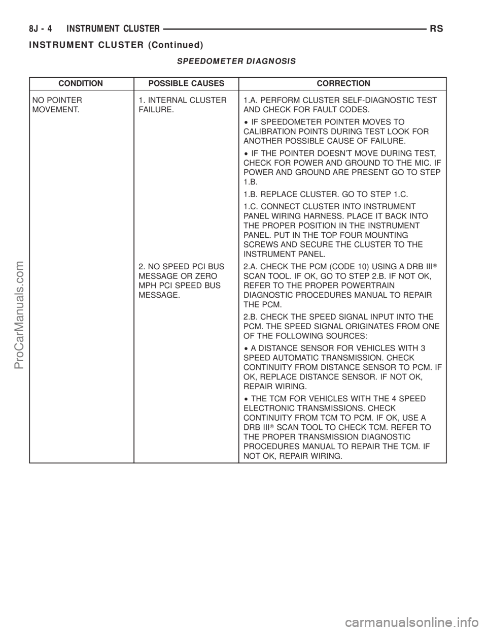
SPEEDOMETER DIAGNOSIS
CONDITION POSSIBLE CAUSES CORRECTION
NO POINTER
MOVEMENT.1. INTERNAL CLUSTER
FAILURE.1.A. PERFORM CLUSTER SELF-DIAGNOSTIC TEST
AND CHECK FOR FAULT CODES.
²IF SPEEDOMETER POINTER MOVES TO
CALIBRATION POINTS DURING TEST LOOK FOR
ANOTHER POSSIBLE CAUSE OF FAILURE.
²IF THE POINTER DOESN'T MOVE DURING TEST,
CHECK FOR POWER AND GROUND TO THE MIC. IF
POWER AND GROUND ARE PRESENT GO TO STEP
1.B.
1.B. REPLACE CLUSTER. GO TO STEP 1.C.
1.C. CONNECT CLUSTER INTO INSTRUMENT
PANEL WIRING HARNESS. PLACE IT BACK INTO
THE PROPER POSITION IN THE INSTRUMENT
PANEL. PUT IN THE TOP FOUR MOUNTING
SCREWS AND SECURE THE CLUSTER TO THE
INSTRUMENT PANEL.
2. NO SPEED PCI BUS
MESSAGE OR ZERO
MPH PCI SPEED BUS
MESSAGE.2.A. CHECK THE PCM (CODE 10) USING A DRB IIIT
SCAN TOOL. IF OK, GO TO STEP 2.B. IF NOT OK,
REFER TO THE PROPER POWERTRAIN
DIAGNOSTIC PROCEDURES MANUAL TO REPAIR
THE PCM.
2.B. CHECK THE SPEED SIGNAL INPUT INTO THE
PCM. THE SPEED SIGNAL ORIGINATES FROM ONE
OF THE FOLLOWING SOURCES:
²A DISTANCE SENSOR FOR VEHICLES WITH 3
SPEED AUTOMATIC TRANSMISSION. CHECK
CONTINUITY FROM DISTANCE SENSOR TO PCM. IF
OK, REPLACE DISTANCE SENSOR. IF NOT OK,
REPAIR WIRING.
²THE TCM FOR VEHICLES WITH THE 4 SPEED
ELECTRONIC TRANSMISSIONS. CHECK
CONTINUITY FROM TCM TO PCM. IF OK, USE A
DRB IIITSCAN TOOL TO CHECK TCM. REFER TO
THE PROPER TRANSMISSION DIAGNOSTIC
PROCEDURES MANUAL TO REPAIR THE TCM. IF
NOT OK, REPAIR WIRING.
8J - 4 INSTRUMENT CLUSTERRS
INSTRUMENT CLUSTER (Continued)
ProCarManuals.com
Page 492 of 2399
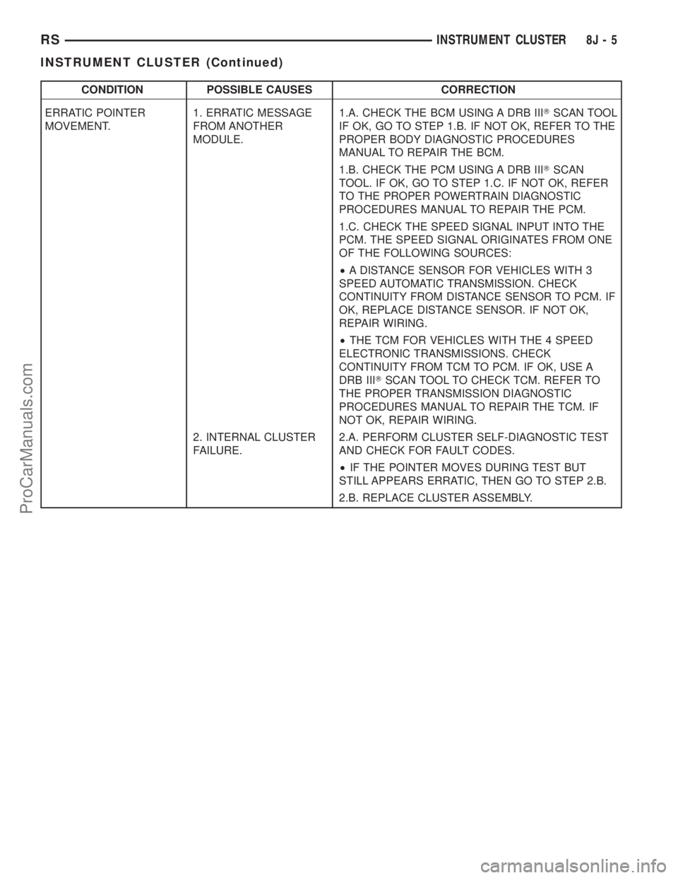
CONDITION POSSIBLE CAUSES CORRECTION
ERRATIC POINTER
MOVEMENT.1. ERRATIC MESSAGE
FROM ANOTHER
MODULE.1.A. CHECK THE BCM USING A DRB IIITSCAN TOOL
IF OK, GO TO STEP 1.B. IF NOT OK, REFER TO THE
PROPER BODY DIAGNOSTIC PROCEDURES
MANUAL TO REPAIR THE BCM.
1.B. CHECK THE PCM USING A DRB IIITSCAN
TOOL. IF OK, GO TO STEP 1.C. IF NOT OK, REFER
TO THE PROPER POWERTRAIN DIAGNOSTIC
PROCEDURES MANUAL TO REPAIR THE PCM.
1.C. CHECK THE SPEED SIGNAL INPUT INTO THE
PCM. THE SPEED SIGNAL ORIGINATES FROM ONE
OF THE FOLLOWING SOURCES:
²A DISTANCE SENSOR FOR VEHICLES WITH 3
SPEED AUTOMATIC TRANSMISSION. CHECK
CONTINUITY FROM DISTANCE SENSOR TO PCM. IF
OK, REPLACE DISTANCE SENSOR. IF NOT OK,
REPAIR WIRING.
²THE TCM FOR VEHICLES WITH THE 4 SPEED
ELECTRONIC TRANSMISSIONS. CHECK
CONTINUITY FROM TCM TO PCM. IF OK, USE A
DRB IIITSCAN TOOL TO CHECK TCM. REFER TO
THE PROPER TRANSMISSION DIAGNOSTIC
PROCEDURES MANUAL TO REPAIR THE TCM. IF
NOT OK, REPAIR WIRING.
2. INTERNAL CLUSTER
FAILURE.2.A. PERFORM CLUSTER SELF-DIAGNOSTIC TEST
AND CHECK FOR FAULT CODES.
²IF THE POINTER MOVES DURING TEST BUT
STILL APPEARS ERRATIC, THEN GO TO STEP 2.B.
2.B. REPLACE CLUSTER ASSEMBLY.
RSINSTRUMENT CLUSTER8J-5
INSTRUMENT CLUSTER (Continued)
ProCarManuals.com
Page 493 of 2399
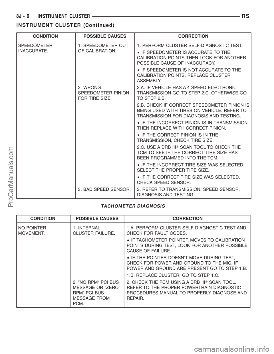
CONDITION POSSIBLE CAUSES CORRECTION
SPEEDOMETER
INACCURATE.1. SPEEDOMETER OUT
OF CALIBRATION.1. PERFORM CLUSTER SELF-DIAGNOSTIC TEST.
²IF SPEEDOMETER IS ACCURATE TO THE
CALIBRATION POINTS THEN LOOK FOR ANOTHER
POSSIBLE CAUSE OF INACCURACY.
²IF SPEEDOMETER IS NOT ACCURATE TO THE
CALIBRATION POINTS, REPLACE CLUSTER
ASSEMBLY.
2. WRONG
SPEEDOMETER PINION
FOR TIRE SIZE.2.A. IF VEHICLE HAS A 4 SPEED ELECTRONIC
TRANSMISSION GO TO STEP 2.C. OTHERWISE GO
TO STEP 2.B.
2.B. CHECK IF CORRECT SPEEDOMETER PINION IS
BEING USED WITH TIRES ON VEHICLE. REFER TO
TRANSMISSION FOR DIAGNOSIS AND TESTING.
²IF THE INCORRECT PINION IS IN TRANSMISSION
THEN REPLACE WITH CORRECT PINION.
²IF THE CORRECT PINION IS IN THE
TRANSMISSION, CHECK TIRE SIZE.
2.C. USE A DRB IIITSCAN TOOL TO CHECK THE
TCM TO SEE IF THE CORRECT TIRE SIZE HAS
BEEN PROGRAMMED INTO THE TCM.
²IF THE INCORRECT TIRE SIZE WAS SELECTED,
SELECT THE PROPER TIRE SIZE.
²IF THE CORRECT TIRE SIZE WAS SELECTED,
CHECK SPEED SENSOR.
3. BAD SPEED SENSOR. 3. REFER TO TRANSMISSION, SPEED SENSOR,
DIAGNOSIS AND TESTING.
TACHOMETER DIAGNOSIS
CONDITION POSSIBLE CAUSES CORRECTION
NO POINTER
MOVEMENT.1. INTERNAL
CLUSTER FAILURE.1.A. PERFORM CLUSTER SELF-DIAGNOSTIC TEST AND
CHECK FOR FAULT CODES.
²IF TACHOMETER POINTER MOVES TO CALIBRATION
POINTS DURING TEST, LOOK FOR ANOTHER POSSIBLE
CAUSE OF FAILURE.
²IF THE POINTER DOESN'T MOVE DURING TEST,
CHECK FOR POWER AND GROUND TO THE MIC. IF
POWER AND GROUND ARE PRESENT GO TO STEP 1.B.
1.B. REPLACE CLUSTER. GO TO STEP 1.C.
2.9NO RPM9PCI BUS
MESSAGE OR9ZERO
RPM9PCI BUS
MESSAGE FROM
PCM.2. CHECK THE PCM USING A DRB IIITSCAN TOOL.
REFER TO THE PROPER POWERTRAIN DIAGNOSTIC
PROCEDURES MANUAL TO PROPERLY DIAGNOSE AND
REPAIR.
8J - 6 INSTRUMENT CLUSTERRS
INSTRUMENT CLUSTER (Continued)
ProCarManuals.com
Page 494 of 2399
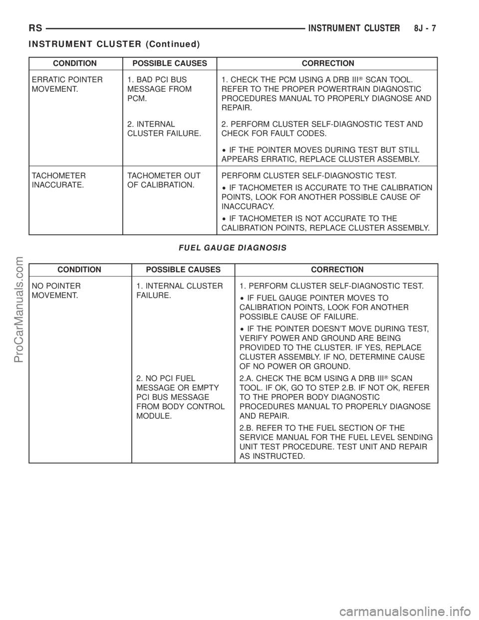
CONDITION POSSIBLE CAUSES CORRECTION
ERRATIC POINTER
MOVEMENT.1. BAD PCI BUS
MESSAGE FROM
PCM.1. CHECK THE PCM USING A DRB IIITSCAN TOOL.
REFER TO THE PROPER POWERTRAIN DIAGNOSTIC
PROCEDURES MANUAL TO PROPERLY DIAGNOSE AND
REPAIR.
2. INTERNAL
CLUSTER FAILURE.2. PERFORM CLUSTER SELF-DIAGNOSTIC TEST AND
CHECK FOR FAULT CODES.
²IF THE POINTER MOVES DURING TEST BUT STILL
APPEARS ERRATIC, REPLACE CLUSTER ASSEMBLY.
TACHOMETER
INACCURATE.TACHOMETER OUT
OF CALIBRATION.PERFORM CLUSTER SELF-DIAGNOSTIC TEST.
²IF TACHOMETER IS ACCURATE TO THE CALIBRATION
POINTS, LOOK FOR ANOTHER POSSIBLE CAUSE OF
INACCURACY.
²IF TACHOMETER IS NOT ACCURATE TO THE
CALIBRATION POINTS, REPLACE CLUSTER ASSEMBLY.
FUEL GAUGE DIAGNOSIS
CONDITION POSSIBLE CAUSES CORRECTION
NO POINTER
MOVEMENT.1. INTERNAL CLUSTER
FAILURE.1. PERFORM CLUSTER SELF-DIAGNOSTIC TEST.
²IF FUEL GAUGE POINTER MOVES TO
CALIBRATION POINTS, LOOK FOR ANOTHER
POSSIBLE CAUSE OF FAILURE.
²IF THE POINTER DOESN'T MOVE DURING TEST,
VERIFY POWER AND GROUND ARE BEING
PROVIDED TO THE CLUSTER. IF YES, REPLACE
CLUSTER ASSEMBLY. IF NO, DETERMINE CAUSE
OF NO POWER OR GROUND.
2. NO PCI FUEL
MESSAGE OR EMPTY
PCI BUS MESSAGE
FROM BODY CONTROL
MODULE.2.A. CHECK THE BCM USING A DRB IIITSCAN
TOOL. IF OK, GO TO STEP 2.B. IF NOT OK, REFER
TO THE PROPER BODY DIAGNOSTIC
PROCEDURES MANUAL TO PROPERLY DIAGNOSE
AND REPAIR.
2.B. REFER TO THE FUEL SECTION OF THE
SERVICE MANUAL FOR THE FUEL LEVEL SENDING
UNIT TEST PROCEDURE. TEST UNIT AND REPAIR
AS INSTRUCTED.
RSINSTRUMENT CLUSTER8J-7
INSTRUMENT CLUSTER (Continued)
ProCarManuals.com