instrument cluster CHRYSLER VOYAGER 2002 Owner's Manual
[x] Cancel search | Manufacturer: CHRYSLER, Model Year: 2002, Model line: VOYAGER, Model: CHRYSLER VOYAGER 2002Pages: 2399, PDF Size: 57.96 MB
Page 495 of 2399
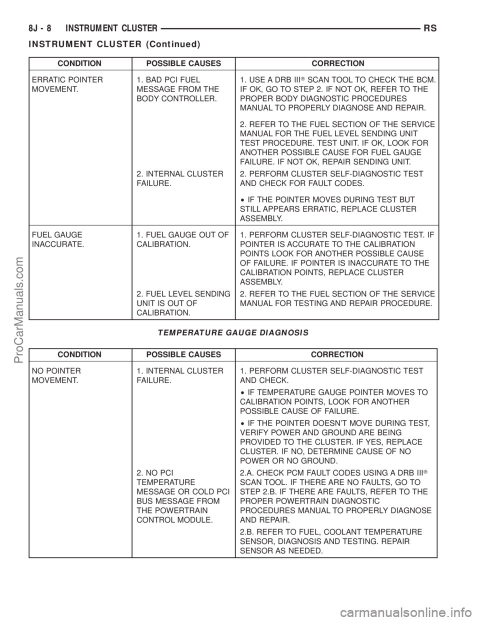
CONDITION POSSIBLE CAUSES CORRECTION
ERRATIC POINTER
MOVEMENT.1. BAD PCI FUEL
MESSAGE FROM THE
BODY CONTROLLER.1. USE A DRB IIITSCAN TOOL TO CHECK THE BCM.
IF OK, GO TO STEP 2. IF NOT OK, REFER TO THE
PROPER BODY DIAGNOSTIC PROCEDURES
MANUAL TO PROPERLY DIAGNOSE AND REPAIR.
2. REFER TO THE FUEL SECTION OF THE SERVICE
MANUAL FOR THE FUEL LEVEL SENDING UNIT
TEST PROCEDURE. TEST UNIT. IF OK, LOOK FOR
ANOTHER POSSIBLE CAUSE FOR FUEL GAUGE
FAILURE. IF NOT OK, REPAIR SENDING UNIT.
2. INTERNAL CLUSTER
FAILURE.2. PERFORM CLUSTER SELF-DIAGNOSTIC TEST
AND CHECK FOR FAULT CODES.
²IF THE POINTER MOVES DURING TEST BUT
STILL APPEARS ERRATIC, REPLACE CLUSTER
ASSEMBLY.
FUEL GAUGE
INACCURATE.1. FUEL GAUGE OUT OF
CALIBRATION.1. PERFORM CLUSTER SELF-DIAGNOSTIC TEST. IF
POINTER IS ACCURATE TO THE CALIBRATION
POINTS LOOK FOR ANOTHER POSSIBLE CAUSE
OF FAILURE. IF POINTER IS INACCURATE TO THE
CALIBRATION POINTS, REPLACE CLUSTER
ASSEMBLY.
2. FUEL LEVEL SENDING
UNIT IS OUT OF
CALIBRATION.2. REFER TO THE FUEL SECTION OF THE SERVICE
MANUAL FOR TESTING AND REPAIR PROCEDURE.
TEMPERATURE GAUGE DIAGNOSIS
CONDITION POSSIBLE CAUSES CORRECTION
NO POINTER
MOVEMENT.1. INTERNAL CLUSTER
FAILURE.1. PERFORM CLUSTER SELF-DIAGNOSTIC TEST
AND CHECK.
²IF TEMPERATURE GAUGE POINTER MOVES TO
CALIBRATION POINTS, LOOK FOR ANOTHER
POSSIBLE CAUSE OF FAILURE.
²IF THE POINTER DOESN'T MOVE DURING TEST,
VERIFY POWER AND GROUND ARE BEING
PROVIDED TO THE CLUSTER. IF YES, REPLACE
CLUSTER. IF NO, DETERMINE CAUSE OF NO
POWER OR NO GROUND.
2. NO PCI
TEMPERATURE
MESSAGE OR COLD PCI
BUS MESSAGE FROM
THE POWERTRAIN
CONTROL MODULE.2.A. CHECK PCM FAULT CODES USING A DRB IIIT
SCAN TOOL. IF THERE ARE NO FAULTS, GO TO
STEP 2.B. IF THERE ARE FAULTS, REFER TO THE
PROPER POWERTRAIN DIAGNOSTIC
PROCEDURES MANUAL TO PROPERLY DIAGNOSE
AND REPAIR.
2.B. REFER TO FUEL, COOLANT TEMPERATURE
SENSOR, DIAGNOSIS AND TESTING. REPAIR
SENSOR AS NEEDED.
8J - 8 INSTRUMENT CLUSTERRS
INSTRUMENT CLUSTER (Continued)
ProCarManuals.com
Page 496 of 2399
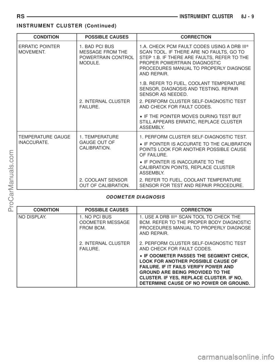
CONDITION POSSIBLE CAUSES CORRECTION
ERRATIC POINTER
MOVEMENT.1. BAD PCI BUS
MESSAGE FROM THE
POWERTRAIN CONTROL
MODULE.1.A. CHECK PCM FAULT CODES USING A DRB IIIT
SCAN TOOL. IF THERE ARE NO FAULTS, GO TO
STEP 1.B. IF THERE ARE FAULTS, REFER TO THE
PROPER POWERTRAIN DIAGNOSTIC
PROCEDURES MANUAL TO PROPERLY DIAGNOSE
AND REPAIR.
1.B. REFER TO FUEL, COOLANT TEMPERATURE
SENSOR, DIAGNOSIS AND TESTING. REPAIR
SENSOR AS NEEDED.
2. INTERNAL CLUSTER
FAILURE.2. PERFORM CLUSTER SELF-DIAGNOSTIC TEST
AND CHECK FOR FAULT CODES.
²IF THE POINTER MOVES DURING TEST BUT
STILL APPEARS ERRATIC, REPLACE CLUSTER
ASSEMBLY.
TEMPERATURE GAUGE
INACCURATE.1. TEMPERATURE
GAUGE OUT OF
CALIBRATION.1. PERFORM CLUSTER SELF-DIAGNOSTIC TEST.
²IF POINTER IS ACCURATE TO THE CALIBRATION
POINTS LOOK FOR ANOTHER POSSIBLE CAUSE
OF FAILURE.
²IF POINTER IS INACCURATE TO THE
CALIBRATION POINTS, REPLACE CLUSTER
ASSEMBLY.
2. COOLANT SENSOR
OUT OF CALIBRATION.2. REFER TO FUEL, COOLANT TEMPERATURE
SENSOR FOR TEST AND REPAIR PROCEDURE.
ODOMETER DIAGNOSIS
CONDITION POSSIBLE CAUSES CORRECTION
NO DISPLAY. 1. NO PCI BUS
ODOMETER MESSAGE
FROM BCM.1. USE A DRB IIITSCAN TOOL TO CHECK THE
BCM. REFER TO THE PROPER BODY DIAGNOSTIC
PROCEDURES MANUAL TO PROPERLY DIAGNOSE
AND REPAIR.
2. INTERNAL CLUSTER
FAILURE.2. PERFORM CLUSTER SELF-DIAGNOSTIC TEST
AND CHECK FOR FAULT CODES.
²IF ODOMETER PASSES THE SEGMENT CHECK,
LOOK FOR ANOTHER POSSIBLE CAUSE OF
FAILURE. IF IT FAILS VERIFY POWER AND
GROUND ARE BEING PROVIDED TO THE
CLUSTER. IF YES, REPLACE CLUSTER. IF NO,
DETERMINE CAUSE OF NO POWER OR GROUND.
RSINSTRUMENT CLUSTER8J-9
INSTRUMENT CLUSTER (Continued)
ProCarManuals.com
Page 497 of 2399
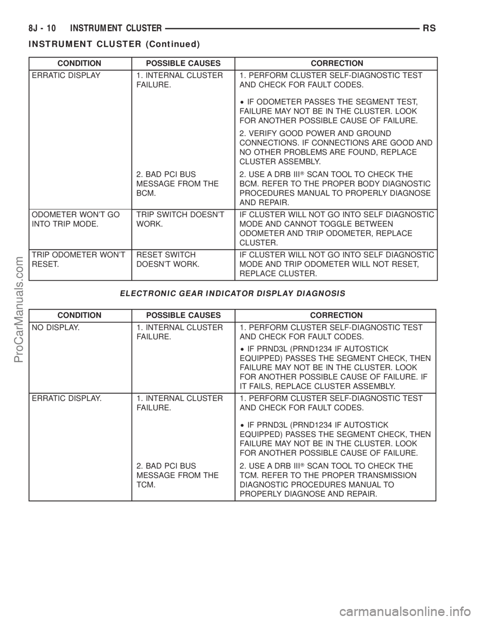
CONDITION POSSIBLE CAUSES CORRECTION
ERRATIC DISPLAY 1. INTERNAL CLUSTER
FAILURE.1. PERFORM CLUSTER SELF-DIAGNOSTIC TEST
AND CHECK FOR FAULT CODES.
²IF ODOMETER PASSES THE SEGMENT TEST,
FAILURE MAY NOT BE IN THE CLUSTER. LOOK
FOR ANOTHER POSSIBLE CAUSE OF FAILURE.
2. VERIFY GOOD POWER AND GROUND
CONNECTIONS. IF CONNECTIONS ARE GOOD AND
NO OTHER PROBLEMS ARE FOUND, REPLACE
CLUSTER ASSEMBLY.
2. BAD PCI BUS
MESSAGE FROM THE
BCM.2. USE A DRB IIITSCAN TOOL TO CHECK THE
BCM. REFER TO THE PROPER BODY DIAGNOSTIC
PROCEDURES MANUAL TO PROPERLY DIAGNOSE
AND REPAIR.
ODOMETER WON'T GO
INTO TRIP MODE.TRIP SWITCH DOESN'T
WORK.IF CLUSTER WILL NOT GO INTO SELF DIAGNOSTIC
MODE AND CANNOT TOGGLE BETWEEN
ODOMETER AND TRIP ODOMETER, REPLACE
CLUSTER.
TRIP ODOMETER WON'T
RESET.RESET SWITCH
DOESN'T WORK.IF CLUSTER WILL NOT GO INTO SELF DIAGNOSTIC
MODE AND TRIP ODOMETER WILL NOT RESET,
REPLACE CLUSTER.
ELECTRONIC GEAR INDICATOR DISPLAY DIAGNOSIS
CONDITION POSSIBLE CAUSES CORRECTION
NO DISPLAY. 1. INTERNAL CLUSTER
FAILURE.1. PERFORM CLUSTER SELF-DIAGNOSTIC TEST
AND CHECK FOR FAULT CODES.
²IF PRND3L (PRND1234 IF AUTOSTICK
EQUIPPED) PASSES THE SEGMENT CHECK, THEN
FAILURE MAY NOT BE IN THE CLUSTER. LOOK
FOR ANOTHER POSSIBLE CAUSE OF FAILURE. IF
IT FAILS, REPLACE CLUSTER ASSEMBLY.
ERRATIC DISPLAY. 1. INTERNAL CLUSTER
FAILURE.1. PERFORM CLUSTER SELF-DIAGNOSTIC TEST
AND CHECK FOR FAULT CODES.
²IF PRND3L (PRND1234 IF AUTOSTICK
EQUIPPED) PASSES THE SEGMENT CHECK, THEN
FAILURE MAY NOT BE IN THE CLUSTER. LOOK
FOR ANOTHER POSSIBLE CAUSE OF FAILURE.
2. BAD PCI BUS
MESSAGE FROM THE
TCM.2. USE A DRB IIITSCAN TOOL TO CHECK THE
TCM. REFER TO THE PROPER TRANSMISSION
DIAGNOSTIC PROCEDURES MANUAL TO
PROPERLY DIAGNOSE AND REPAIR.
8J - 10 INSTRUMENT CLUSTERRS
INSTRUMENT CLUSTER (Continued)
ProCarManuals.com
Page 498 of 2399
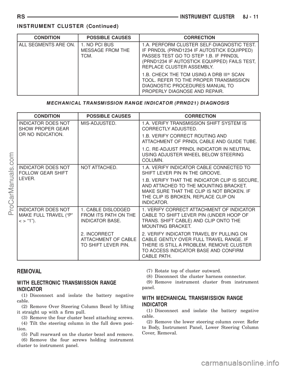
CONDITION POSSIBLE CAUSES CORRECTION
ALL SEGMENTS ARE ON. 1. NO PCI BUS
MESSAGE FROM THE
TCM.1.A. PERFORM CLUSTER SELF-DIAGNOSTIC TEST.
IF PRND3L (PRND1234 IF AUTOSTICK EQUIPPED)
PASSES TEST GO TO STEP 1.B. IF PRND3L
(PRND1234 IF AUTOSTICK EQUIPPED) FAILS TEST,
REPLACE CLUSTER ASSEMBLY.
1.B. CHECK THE TCM USING A DRB IIITSCAN
TOOL. REFER TO THE PROPER TRANSMISSION
DIAGNOSTIC PROCEDURES MANUAL TO
PROPERLY DIAGNOSE AND REPAIR.
MECHANICAL TRANSMISSION RANGE INDICATOR (PRND21) DIAGNOSIS
CONDITION POSSIBLE CAUSES CORRECTION
INDICATOR DOES NOT
SHOW PROPER GEAR
OR NO INDICATION.MIS-ADJUSTED. 1.A. VERIFY TRANSMISSION SHIFT SYSTEM IS
CORRECTLY ADJUSTED.
1.B. VERIFY CORRECT ROUTING AND
ATTACHMENT OF PRNDL CABLE AND GUIDE TUBE.
1.C. RE-ADJUST PRNDL INDICATOR IN NEUTRAL
USING ADJUSTER WHEEL BELOW STEERING
COLUMN.
INDICATOR DOES NOT
FOLLOW GEAR SHIFT
LEVER.NOT ATTACHED. 1.A. VERIFY INDICATOR CABLE CONNECTED TO
SHIFT LEVER PIN IN THE GROOVE.
1.B. VERIFY THAT THE INDICATOR CLIP IS SECURE,
AND ATTACHED TO THE MOUNTING BRACKET.
MAKE SURE THAT THE CLIP IS NOT BROKEN. IF
THE CLIP IS BROKEN, REPLACE CLIP ON
INDICATOR.
INDICATOR DOES NOT
MAKE FULL TRAVEL (ªPº
< > ª1º).1. CABLE DISLODGED
FROM ITS PATH ON THE
INDICATOR BASE.1. VERIFY CORRECT ATTACHMENT OF INDICATOR
CABLE TO SHIFT LEVER PIN (UNDER HOOP OF
TRANS. SHIFT CABLE) AND CLIP ONTO THE
MOUNTING BRACKET.
2. INCORRECT
ATTACHMENT OF CABLE
TO SHIFT LEVER PIN.2. VERIFY INDICATOR TRAVEL BY PULLING ON
CABLE GENTLY OVER FULL TRAVEL RANGE. IF
THERE IS STILL A PROBLEM, REMOVE CLUSTER
TO ACCESS INDICATOR BASE AND CONFIRM
CABLE PATH.
REMOVAL
WITH ELECTRONIC TRANSMISSION RANGE
INDICATOR
(1) Disconnect and isolate the battery negative
cable.
(2) Remove Over Steering Column Bezel by lifting
it straight up with a firm pull.
(3) Remove the four cluster bezel attaching screws.
(4) Tilt the steering column in the full down posi-
tion.
(5) Pull rearward on the cluster bezel and remove.
(6) Remove the four screws holding instrument
cluster to instrument panel.(7) Rotate top of cluster outward.
(8) Disconnect the cluster harness connector.
(9) Remove instrument cluster from instrument
panel.WITH MECHANICAL TRANSMISSION RANGE
INDICATOR
(1) Disconnect and isolate the battery negative
cable.
(2) Remove the lower steering column cover. Refer
to Body, Instrument Panel, Lower Steering Column
Cover, Removal.
RSINSTRUMENT CLUSTER8J-11
INSTRUMENT CLUSTER (Continued)
ProCarManuals.com
Page 499 of 2399
(3) Remove the plastic knee blocker reinforcement.
Refer to Body, Instrument Panel, Knee Blocker Rein-
forcement, Removal.
(4) Disconnect the transmission range indicator
cable end from shift lever by flexing the HOOP on
the transmission shift cable rearward and slip the
indicator cable loop off the lever pin.
(5) Disconnect the clip holding the indicator cable
to the mounting bracket.
(6) Remove Over Steering Column Bezel by lifting
it straight up with a firm pull.
(7) Remove the four bezel attaching screws.
(8) Tilt the steering column in the full down posi-
tion.
(9) Pull rearward on the cluster bezel and remove.
(10) Remove the four cluster attaching screws.
(11) Rotate top of the cluster rearward.
(12) Disconnect the cluster harness connector.
(13) Remove the instrument cluster carefully while
guiding the range indicator cable and guide tube
through the opening to avoid any damage.
INSTALLATION
WITH ELECTRONIC TRANSMISSION RANGE
INDICATOR
(1) Connect the instrument cluster wire connector.
(2) Rotate top of cluster inward as placing into
instrument panel opening.
(3) Install the four screws holding instrument clus-
ter to instrument panel.
(4) Position cluster bezel into place.
(5) Install the four bezel attaching screws.
(6) Install the Over Steering Column Bezel by
firmly snapping into place.
(7) Connect the battery negative cable.
WITH MECHANICAL TRANSMISSION RANGE
INDICATOR
(1) Guide the range indicator cable and guide tube
through the opening of instrument panel.
(2) Connect the instrument cluster wire connector.
(3) Rotate top of cluster inward as placing into
instrument panel opening.
(4) Install the four screws holding instrument clus-
ter to instrument panel.
(5) Position cluster bezel into place.
(6) Install the four bezel attaching screws.
(7) Install the Over Steering Column Bezel by
firmly snapping into place.
(8) Connect the clip holding the indicator cable to
the mounting bracket.(9) Connect the transmission range indicator cable
end to the shift lever by flexing the HOOP on the
transmission shift cable forward and slip the indica-
tor cable loop on the lever pin.
(10) Install the plastic knee blocker reinforcement.
Refer to Body, Instrument Panel, Knee Blocker Rein-
forcement, Installation.
(11) Install the lower steering column cover. Refer
to Body, Instrument Panel, Lower Steering Column
Cover, Installation.
(12) Connect the battery negative cable.
CLUSTER LENS
REMOVAL
(1) Remove the instrument cluster. Refer to Elec-
trical, Instrument Cluster, Removal.
(2) Remove the screws holding the lens to the
instrument cluster.
(3) Press down on the snap features of the lens
and remove the lens from the cluster.
INSTALLATION
(1) Insert the lens snap features into the cluster.
(2) Install the screws holding the lens to the
instrument cluster.
(3) Install the instrument cluster. Refer to Electri-
cal, Instrument Cluster, Installation.
MECHANICAL TRANSMISSION
RANGE INDICATOR
REMOVAL
(1) Remove the instrument cluster and disconnect
the range indicator cable at both attaching points.
Refer to Electrical, Instrument Cluster, Removal.
(2) From the backside of the cluster, remove two
screws holding the mechanical transmission range
indicator and then remove it fromt instrument clus-
ter.
INSTALLATION
(1) Insert the mechanical transmission range indi-
cator into the backside of the instrument cluster and
install the two screws.
(2) Install the instrument cluster. Refer to Electri-
cal, Instrument Cluster, Installation.
8J - 12 INSTRUMENT CLUSTERRS
INSTRUMENT CLUSTER (Continued)
ProCarManuals.com
Page 500 of 2399
RED BRAKE WARNING
INDICATOR
DESCRIPTION
The red BRAKE warning indicator (lamp) is
located in the instrument panel cluster and is used to
indicate a low brake fluid condition or that the park-
ing brake is applied. In addition, the brake warning
indicator is turned on as a bulb check by the ignition
switch every time the ignition switch is placed in the
crank position.
OPERATION
The red BRAKE warning indicator (lamp) is sup-
plied a 12-volt ignition feed anytime the ignition
switch is on. The bulb is then illuminated by com-
pleting the ground circuit either through the switch
on the parking brake lever, the brake fluid level
switch in the master cylinder reservoir, or the igni-
tion switch when it is placed in the crank position.
RSINSTRUMENT CLUSTER8J-13
ProCarManuals.com
Page 522 of 2399
(4) Reconnect the battery negative cable.
LICENSE LAMP
REMOVAL
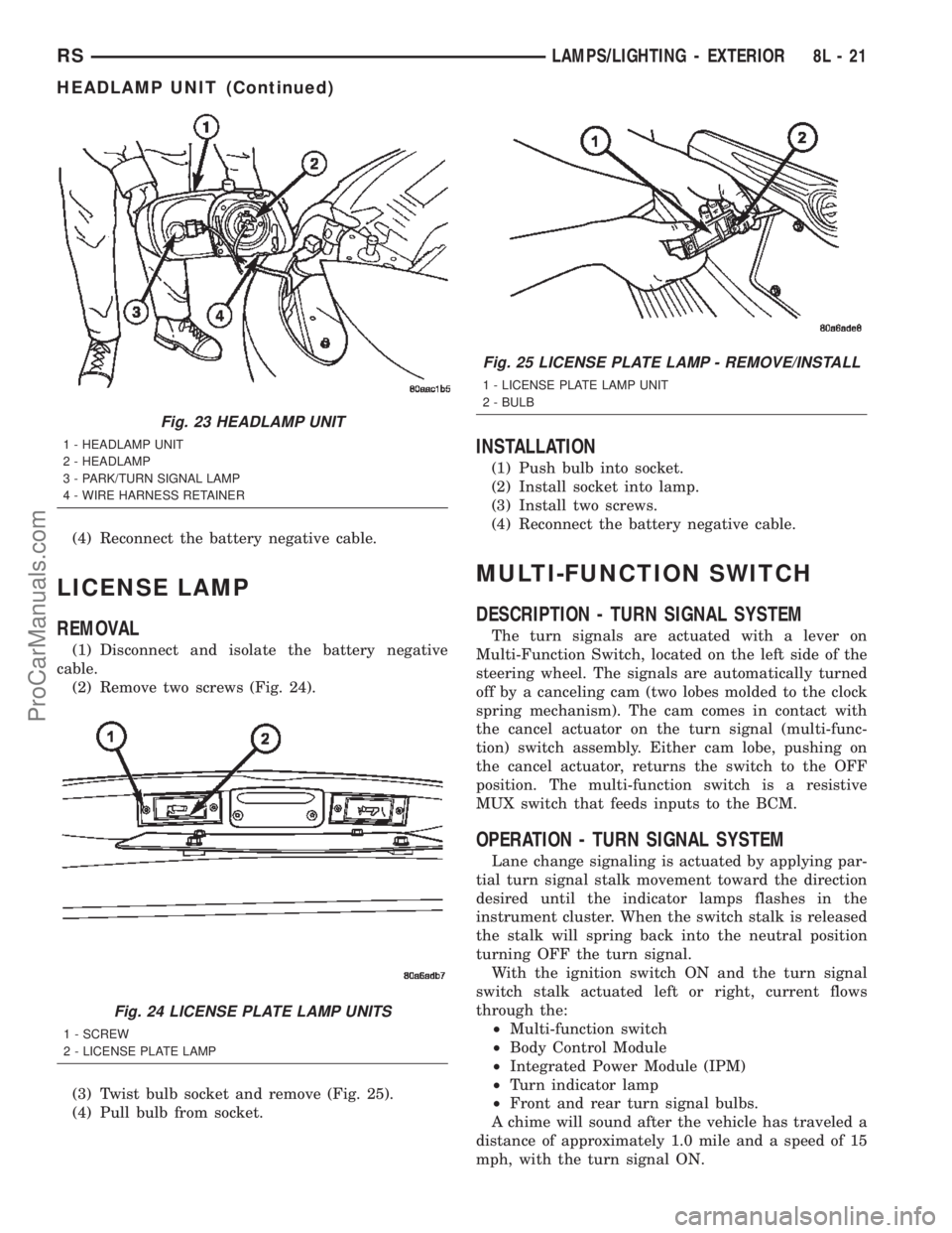
(1) Disconnect and isolate the battery negative
cable.
(2) Remove two screws (Fig. 24).
(3) Twist bulb socket and remove (Fig. 25).
(4) Pull bulb from socket.
INSTALLATION
(1) Push bulb into socket.
(2) Install socket into lamp.
(3) Install two screws.
(4) Reconnect the battery negative cable.
MULTI-FUNCTION SWITCH
DESCRIPTION - TURN SIGNAL SYSTEM
The turn signals are actuated with a lever on
Multi-Function Switch, located on the left side of the
steering wheel. The signals are automatically turned
off by a canceling cam (two lobes molded to the clock
spring mechanism). The cam comes in contact with
the cancel actuator on the turn signal (multi-func-
tion) switch assembly. Either cam lobe, pushing on
the cancel actuator, returns the switch to the OFF
position. The multi-function switch is a resistive
MUX switch that feeds inputs to the BCM.
OPERATION - TURN SIGNAL SYSTEM
Lane change signaling is actuated by applying par-
tial turn signal stalk movement toward the direction
desired until the indicator lamps flashes in the
instrument cluster. When the switch stalk is released
the stalk will spring back into the neutral position
turning OFF the turn signal.
With the ignition switch ON and the turn signal
switch stalk actuated left or right, current flows
through the:
²Multi-function switch
²Body Control Module
²Integrated Power Module (IPM)
²Turn indicator lamp
²Front and rear turn signal bulbs.
A chime will sound after the vehicle has traveled a
distance of approximately 1.0 mile and a speed of 15
mph, with the turn signal ON.
Fig. 23 HEADLAMP UNIT
1 - HEADLAMP UNIT
2 - HEADLAMP
3 - PARK/TURN SIGNAL LAMP
4 - WIRE HARNESS RETAINER
Fig. 24 LICENSE PLATE LAMP UNITS
1 - SCREW
2 - LICENSE PLATE LAMP
Fig. 25 LICENSE PLATE LAMP - REMOVE/INSTALL
1 - LICENSE PLATE LAMP UNIT
2 - BULB
RSLAMPS/LIGHTING - EXTERIOR8L-21
HEADLAMP UNIT (Continued)
ProCarManuals.com
Page 527 of 2399

CENTER CONSOLE LAMP
SWITCH
REMOVAL
(1)Disconnect and isolate the battery negative cable.
(2) Open console lid and remove tray.
(3) Using a flat bladed tool, pry up on the switch.
(4) Remove bulb from switch.
INSTALLATION
(1) Install bulb into switch.
(2) Push switch into console opening.
(3) Install tray and close lid.
(4) Connect battery negative cable.
CLUSTER ILLUMINATION
LAMPS
REMOVAL
(1) Remove the Instrument Cluster. Refer to Elec-
trical, Instrument Cluster, Removal.
(2) Turn over cluster and expose the illumination
bulb sockets.
(3) Identify which bulb is defective and twist it out
of the cluster using a counterclockwise motion.
INSTALLATION
(1) Install the new bulb socket into the cluster
using a clockwise motion.
(2) Install the Instrument Cluster. Refer to Electri-
cal, Instrument Cluster, Installation.
COURTESY LAMP
REMOVAL
(1)Disconnect and isolate the battery negative cable.
(2) Using a trim stick, pry lamp from door panel
(Fig. 1).
(3) Disconnect wire harness from the lamp.
(4) Remove lens from the lamp and remove bulb.
INSTALLATION
(1) Install bulb and lens to lamp.
(2) Reconnect wire harness to lamp.
(3) Press lamp into the door panel.
(4) Reconnect battery negative cable.
DOME LAMP
REMOVAL
(1) Disconnect and isolate the battery negative
cable.(2) Using a flat bladed tool, pry off the lamp lens.
(3) Remove bulb from lamp.
INSTALLATION
(1) Install bulb to lamp.
(2) Press lens into place.
(3) Connect battery negative cable.
GLOVE BOX LAMP SWITCH
REMOVAL
(1) Disconnect and isolate the battery negative
cable.
(2) Open glove box door.
(3) Push switch through from behind (Fig. 2).
(4) Disconnect wire harness from switch.
(5) Pull bulb from switch.
Fig. 1 COURTESY LAMP
1 - WIRE HARNESS
2 - COURTESY LAMP
Fig. 2 GLOVE BOX LAMP/SWITCH
1 - GLOVE BOX BULB
2 - GLOVE BOX LAMP SWITCH
8L - 26 LAMPS/LIGHTING - INTERIORRS
ProCarManuals.com
Page 536 of 2399
nications and the BCM. If the brightness level is
improper check the J1850 Data Bus circuit.
The DRB IIItis recommended for checking the
J1850 Data Bus circuit and the BCM. Perform the
EVIC self diagnosis before replacing the EVIC mod-
ule.
STANDARD PROCEDURE - ELECTRONIC
VEHICLE INFORMATION CENTER
PROGRAMMING
EVIC PROGRAMMING MODE
Some vehicles are equipped with a Electronic Vehi-
cle Information Center (EVIC) equipped overhead
console. The Electronic Vehicle Information Center
(EVIC) provides the vehicle operator with a user
interface, which allows the selection of several
optional customer programmable electronic features
to suit individual preferences. The EVIC must be
placed into its programming mode in order to view or
change the programmable features. To enter the
EVIC programming mode and to view or change the
selected programmable features options, proceed as
follows:
(1) Turn the ignition switch to the On position.
(2) Depress and release the Menu push button.
The first item in the programmable features menu
list will appear in the EVIC display.
(3) Momentarily depress and release the Menu
push button to step through the programmable fea-
tures list. Each programmable feature and its cur-
rently selected option will appear on the EVIC
display in the sequence shown in the Programmable
Features list that follows.
(4) Momentarily depress and release the Step push
button to step through the available options for the
programmable feature being displayed.
(5) The option that last appears in the display
with a programmable feature before exiting the pro-
gramming mode, becomes the newly selected pro-
grammable feature option.
(6) The EVIC exits the programming mode and
returns to its normal operating mode when the C/T
push button is depressed or when the end of the pro-
grammable features menu list is reached, whichever
occurs first.
PROGRAMMABLE FEATURES
NOTE: TIRE PRESSURE MONITORING (TPM) SYS-
TEM INFORMATION IS NOT COVERED IN THIS SEC-
TION OF THE SERVICE MANUAL. REFER TO THE
TIRES/WHEELS SECTION OF THIS MANUAL FOR
DETAILED TPM SYSTEM INFORMATION.²LANGUAGE?- The options include English,
Francaise, Deutsch, Italiana, or Espanol. The default
is English. All EVIC display nomenclature, including
the trip computer functions, warning messages and
the programmable features appear in the selected
language.
²DISPLAY U.S. OR METRIC?- The options
include U.S. and M. The default is U.S. This feature
toggles the trip computer temperature, fuel economy
and odometer display readings between U.S. and
metric units of measure. It also changes the odome-
ter display in the instrument cluster.
²SERVICE INTV. =- The options include from
1000 to 12000 kilometers in 1000 kilometer incre-
ments (2000 to 7500 miles in 500 mile increments).
The default is 12000 kilometers (7500 miles). The
selected distance becomes the interval at which the
Perform Service warning message will be displayed
by the EVIC. If a new distance is selected, a second
programmable feature appears,RESET SERVICE
DISTANCE?- The options include No and Yes. The
default is Yes. When Yes is selected, the accumulated
distance since the last previous Perform Service
warning message will be reset to zero because the
service interval has been changed. When No is
selected, the distance until the next Perform Service
warning message is reduced by the accumulated dis-
tance since the last previous message.
²USE FACTORY SETTINGS?- The options
include Yes and No. The default is Yes. When yes is
selected all the programmable features will return to
there defaults and the rest of the programmable fea-
tures will not be displayed. If No is selected the rest
of the programmable features will be displayed at
there default values. This feature will automatically
return to the Yes default under two conditions. First,
if no programmable features are changed from there
defaults. Second, if all the programmable features
equal there defaults.
²AUTO DOOR LOCKS?- The options include
Yes and No. The default is Yes. When Yes is selected,
all doors and the liftgate lock automatically when
vehicle speed reaches 25 kilometers-per-hour (15
miles-per-hour). If YES is selected, a second program-
mable feature appears,AUTO UNLOCK ON EXIT?
- The options again include Yes and No. The default
is No. When Yes is selected, following each Auto Door
Lock event all doors and the liftgate will automati-
cally unlock when the driver door is opened, if the
vehicle is stopped and the transmission gear selector
is in Park or Neutral. The Auto Door Unlock event
will only occur once following each Auto Door Lock
event.
²REMOTE UNLOCK- The options include
Driver Door 1st and All Doors. The default is Driver
Door 1st. When Diver Door 1st is selected, only the
RSMESSAGE SYSTEMS8M-7
ELECTRONIC VEHICLE INFO CENTER (Continued)
ProCarManuals.com
Page 658 of 2399
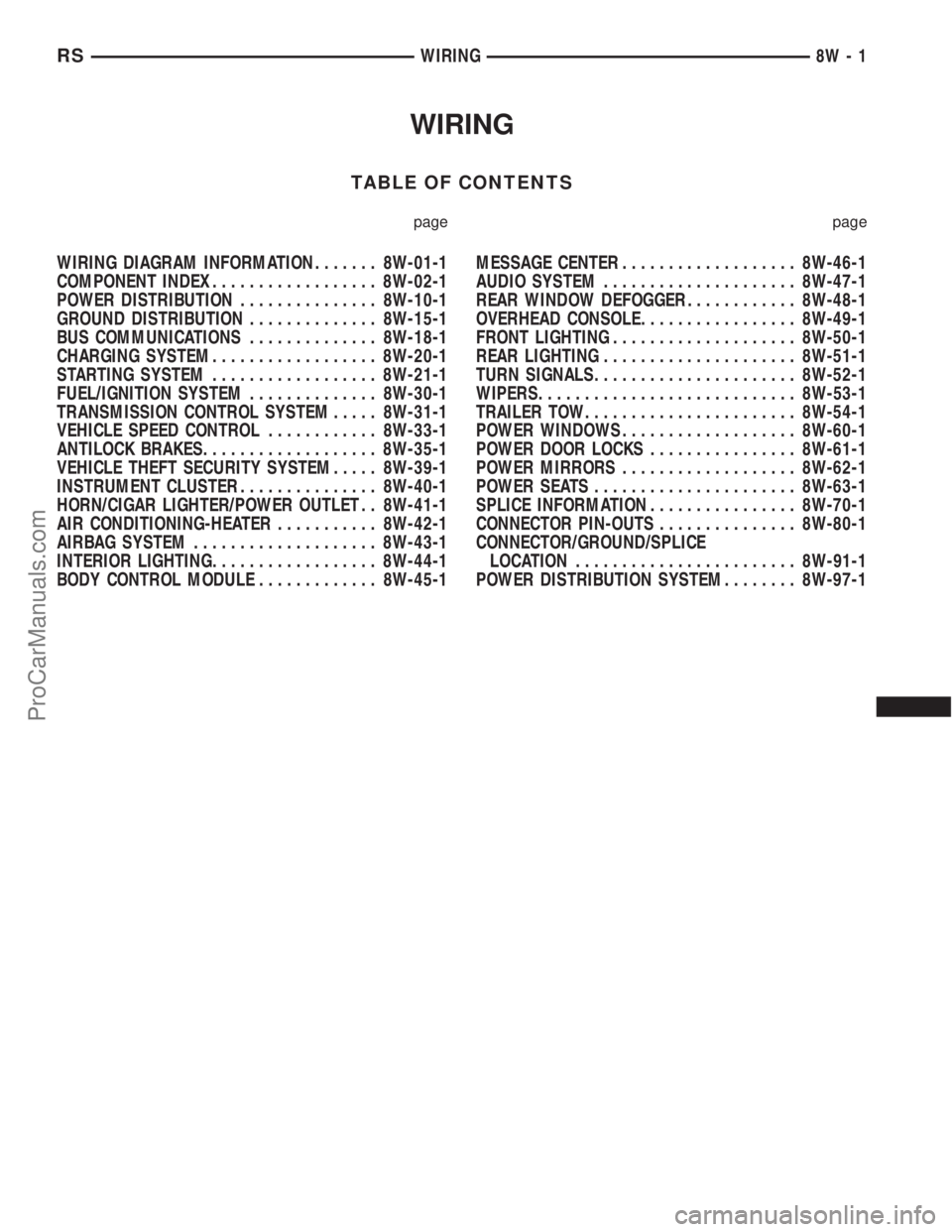
WIRING
TABLE OF CONTENTS
page page
WIRING DIAGRAM INFORMATION....... 8W-01-1
COMPONENT INDEX.................. 8W-02-1
POWER DISTRIBUTION............... 8W-10-1
GROUND DISTRIBUTION.............. 8W-15-1
BUS COMMUNICATIONS.............. 8W-18-1
CHARGING SYSTEM.................. 8W-20-1
STARTING SYSTEM.................. 8W-21-1
FUEL/IGNITION SYSTEM.............. 8W-30-1
TRANSMISSION CONTROL SYSTEM..... 8W-31-1
VEHICLE SPEED CONTROL............ 8W-33-1
ANTILOCK BRAKES................... 8W-35-1
VEHICLE THEFT SECURITY SYSTEM..... 8W-39-1
INSTRUMENT CLUSTER............... 8W-40-1
HORN/CIGAR LIGHTER/POWER OUTLET . . 8W-41-1
AIR CONDITIONING-HEATER........... 8W-42-1
AIRBAG SYSTEM.................... 8W-43-1
INTERIOR LIGHTING.................. 8W-44-1
BODY CONTROL MODULE............. 8W-45-1MESSAGE CENTER................... 8W-46-1
AUDIO SYSTEM..................... 8W-47-1
REAR WINDOW DEFOGGER............ 8W-48-1
OVERHEAD CONSOLE................. 8W-49-1
FRONT LIGHTING.................... 8W-50-1
REAR LIGHTING..................... 8W-51-1
TURN SIGNALS...................... 8W-52-1
WIPERS............................ 8W-53-1
TRAILER TOW....................... 8W-54-1
POWER WINDOWS................... 8W-60-1
POWER DOOR LOCKS................ 8W-61-1
POWER MIRRORS................... 8W-62-1
POWER SEATS...................... 8W-63-1
SPLICE INFORMATION................ 8W-70-1
CONNECTOR PIN-OUTS............... 8W-80-1
CONNECTOR/GROUND/SPLICE
LOCATION........................ 8W-91-1
POWER DISTRIBUTION SYSTEM........ 8W-97-1 RSWIRING
8W-1
ProCarManuals.com