Ignition CHRYSLER VOYAGER 2002 Service Manual
[x] Cancel search | Manufacturer: CHRYSLER, Model Year: 2002, Model line: VOYAGER, Model: CHRYSLER VOYAGER 2002Pages: 2399, PDF Size: 57.96 MB
Page 1532 of 2399
(17) Remove the 3 bolts and nuts mounting the
steering gear to the front suspension cradle (Fig. 8).
NOTE: The next step must be done to allow the
removal of the steering gear from the front suspen-
sion cradle. The steering gear can not be removed
from the vehicle with the intermediate coupler
attached to the steering gear.
(18) Lower steering gear from suspension cradle
enough to allow access to the intermediate coupler
roll pin (Fig. 9). Install Remover/Installer Special
Tool 6831A through the center of the roll pin, secur-
ing with the knurled nut (Fig. 9). Hold threaded rod
stationary while turning nut, this will pull the roll
pin out of the intermediate coupler.
(19) Separate the coupler from the shaft of the
steering gear.(20) Remove the power steering gear from the
vehicle.
REMOVAL - RHD GEAR
(1) Remove cap from power steering fluid reser-
voir.
(2) Using a siphon pump, remove as much fluid as
possible from the power steering fluid reservoir.
CAUTION: Locking the steering column in the
straight-ahead position will prevent the clockspring
from being accidentally over-extended when the
steering column is disconnected from the interme-
diate steering coupler.
(3) Position the steering wheel in the STRAIGHT-
AHEAD position. Lock the steering wheel in place
using a steering wheel holding tool.
(4) With the ignition key in the locked position
turn the steering wheel to the left until the steering
wheel is in the locked position.
(5) With the vehicle on the ground, disconnect the
steering column shaft coupler from the steering gear
intermediate coupler (Fig. 2).
(6) Raise vehicle. (Refer to LUBRICATION &
MAINTENANCE/HOISTING - STANDARD PROCE-
DURE)
(7) Remove front wheel and tire assemblies.
(8) If power steering cooler equipped, remove a
hose at power steering cooler and allow fluid to
drain.
(9) Remove 2 bolts attaching power steering cooler
to cradle crossmember reinforcement (Fig. 3).
(10) On both sides of vehicle, remove nut attaching
outer tie rod end to steering knuckle (Fig. 4).
Remove nut by holding tie rod end stud with a
socket while loosening and removing nut with
wrench.
(11) Remove both tie rod ends from steering
knuckles using Puller, Special Tool C-3894±A (Fig. 5).
(12) Remove the lower control arm rear bushing
retainer bolts located on each side of each lower con-
trol arm rear bushing.
NOTE: The bolts fastening the cradle crossmember
reinforcement are of two different thread sizes. Note
the location of the various sizes.
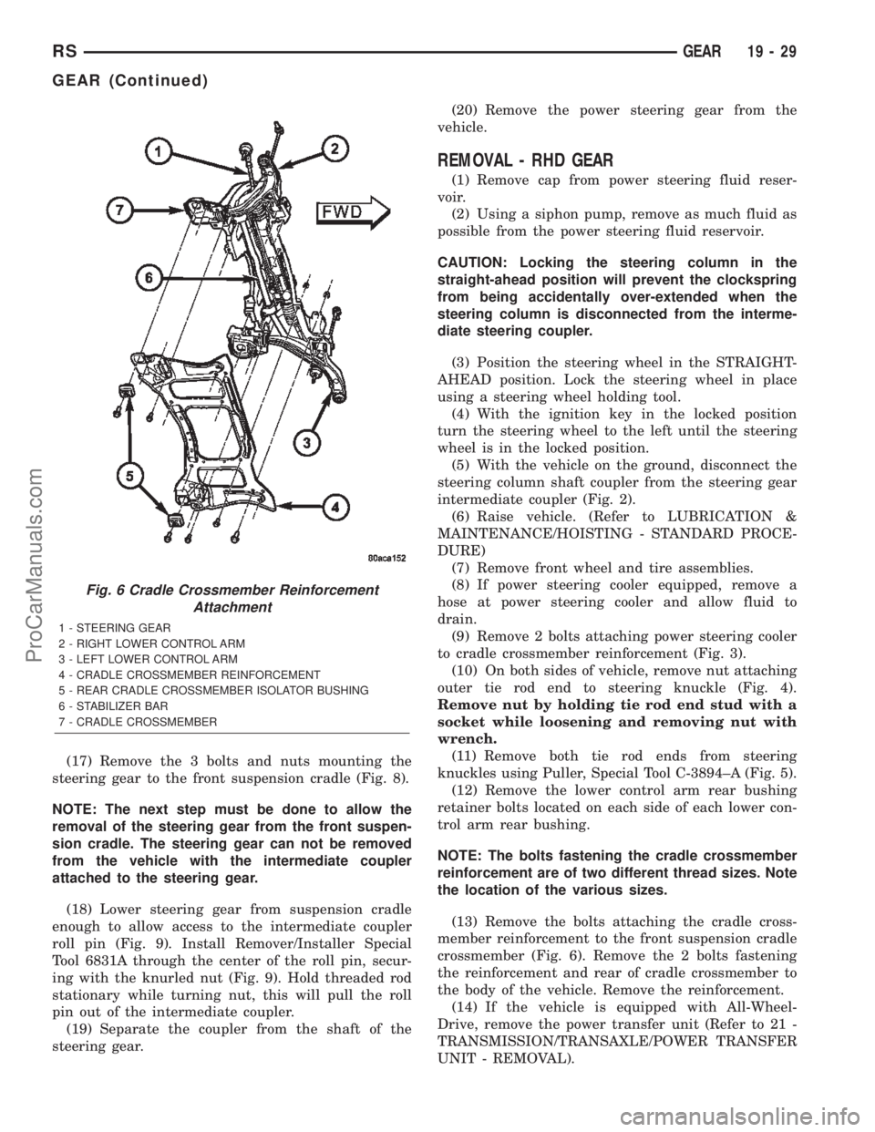
(13) Remove the bolts attaching the cradle cross-
member reinforcement to the front suspension cradle
crossmember (Fig. 6). Remove the 2 bolts fastening
the reinforcement and rear of cradle crossmember to
the body of the vehicle. Remove the reinforcement.
(14) If the vehicle is equipped with All-Wheel-
Drive, remove the power transfer unit (Refer to 21 -
TRANSMISSION/TRANSAXLE/POWER TRANSFER
UNIT - REMOVAL).
Fig. 6 Cradle Crossmember Reinforcement
Attachment
1 - STEERING GEAR
2 - RIGHT LOWER CONTROL ARM
3 - LEFT LOWER CONTROL ARM
4 - CRADLE CROSSMEMBER REINFORCEMENT
5 - REAR CRADLE CROSSMEMBER ISOLATOR BUSHING
6 - STABILIZER BAR
7 - CRADLE CROSSMEMBER
RSGEAR19-29
GEAR (Continued)
ProCarManuals.com
Page 1661 of 2399
ADJUSTMENTS
GEARSHIFT CABLE ADJUSTMENT
Lift and rotate the gearshift hand lever into the
park (P) gate position and remove the ignition key.
This confirms the shift lever is in the gated park (P)
position.
After confirming the park gate position, turn the
ignition switch . If the starter will operate, the park
gate position is correct. Move the shift lever into the
neutral (N) position. If the starter will operate in this
position, the linkage is properly adjusted. If the
starter fails to operate in either position, linkage
adjustment is required.
(1) Park the vehicle on level ground and set the
parking brake.
(2) Place the gearshift lever in park (P) gate posi-
tion and remove key.
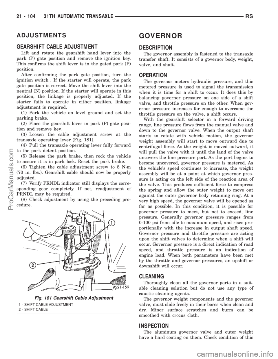
(3) Loosen the cable adjustment screw at the
transaxle operating lever (Fig. 181).
(4) Pull the transaxle operating lever fully forward
to the park detent position.
(5) Release the park brake, then rock the vehicle
to assure it is in park lock. Reset the park brake.
(6) Tighten the cable adjustment screw to 8 N´m
(70 in. lbs.). Gearshift cable should now be properly
adjusted.
(7) Verify PRNDL indicator still displays the corre-
sponding gear completely. If not, readjustment of
PRNDL may be required.
(8) Check adjustment by using the preceding pro-
cedure.
GOVERNOR
DESCRIPTION
The governor assembly is fastened to the transaxle
transfer shaft. It consists of a governor body, weight,
valve, and shaft.
OPERATION
The governor meters hydraulic pressure, and this
metered pressure is used to signal the transmission
when it is time for a shift to occur. It does this by
balancing governor pressure on one side of a shift
valve, and throttle pressure on the other. When gov-
ernor pressure increases far enough to overcome the
throttle pressure on the valve, a shift occurs.
With the gearshift selector in a forward driving
range, line pressure flows from the manual valve and
down to the governor valve. When the output shaft
starts to rotate with vehicle motion, the governor
weight assembly will start to move outward due to
centrifugal force. As the weight is moved outward, it
will pull the valve with it until the land of the valve
uncovers the line pressure port. As the port begins to
become uncovered, governor pressure is metered. As
the vehicle's speed continues to increase, the weight
assembly will be at a point at which governor pres-
sure is acting on the left side of the reaction area of
the valve. This produces sufficient force to compress
the spring and allow the outer weight to move out
against the outer governor body retaining ring. At a
very high speed, the governor valve will be opened as
far as possible. In this condition, it is possible for
governor pressure to meet, but not to exceed, line
pressure. Generally governor pressure ranges from
0-100 psi from idle to maximum speed, and rises pro-
portionally with the increase in output shaft speed.
Governor pressure and throttle pressure are acting
upon the shift valves to determine when a shift will
occur. Governor pressure is a direct indication of road
speed, and throttle pressure is an indication of
engine load. When both parameters have been met
by the throttle and governor pressures, an upshift or
downshift will occur.
CLEANING
Thoroughly clean all the governor parts in a suit-
able cleaning solution but do not use any type of
caustic cleaning agents.
The governor weight components and the governor
valve, must slide freely in their bores when clean and
dry. Minor surface scratches and burrs can be
smoothed with crocus cloth.
INSPECTION
The aluminum governor valve and outer weight
have a hard coating on them. Check condition of this
Fig. 181 Gearshift Cable Adjustment
1 - SHIFT CABLE ADJUSTMENT
2 - SHIFT CABLE
21 - 104 31TH AUTOMATIC TRANSAXLERS
ProCarManuals.com
Page 1672 of 2399
ASSEMBLY
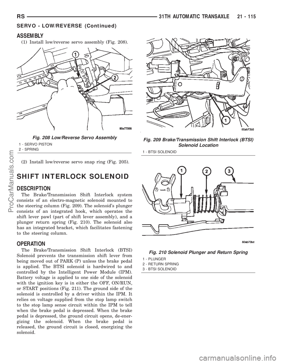
(1) Install low/reverse servo assembly (Fig. 208).
(2) Install low/reverse servo snap ring (Fig. 205).
SHIFT INTERLOCK SOLENOID
DESCRIPTION
The Brake/Transmission Shift Interlock system
consists of an electro-magnetic solenoid mounted to
the steering column (Fig. 209). The solenoid's plunger
consists of an integrated hook, which operates the
shift lever pawl (part of shift lever assembly), and a
plunger return spring (Fig. 210). The solenoid also
has an integrated bracket, which facilitates fastening
to the steering column.
OPERATION
The Brake/Transmission Shift Interlock (BTSI)
Solenoid prevents the transmission shift lever from
being moved out of PARK (P) unless the brake pedal
is applied. The BTSI solenoid is hardwired to and
controlled by the Intelligent Power Module (IPM).
Battery voltage is applied to one side of the solenoid
with the ignition key is in either the OFF, ON/RUN,
or START positions (Fig. 211). The ground side of the
solenoid is controlled by a driver within the IPM. It
relies on voltage supplied from the stop lamp switch
to the stop lamp sense circuit within the IPM to tell
when the brake pedal is depressed. When the brake
pedal is depressed, the ground circuit opens, de-ener-
gizing the solenoid. When the brake pedal is
released, the ground circuit is closed, energizing the
solenoid.
Fig. 208 Low/Reverse Servo Assembly
1 - SERVO PISTON
2 - SPRINGFig. 209 Brake/Transmission Shift Interlock (BTSI)
Solenoid Location
1 - BTSI SOLENOID
Fig. 210 Solenoid Plunger and Return Spring
1 - PLUNGER
2 - RETURN SPRING
3 - BTSI SOLENOID
RS31TH AUTOMATIC TRANSAXLE21 - 115
SERVO - LOW/REVERSE (Continued)
ProCarManuals.com
Page 1673 of 2399
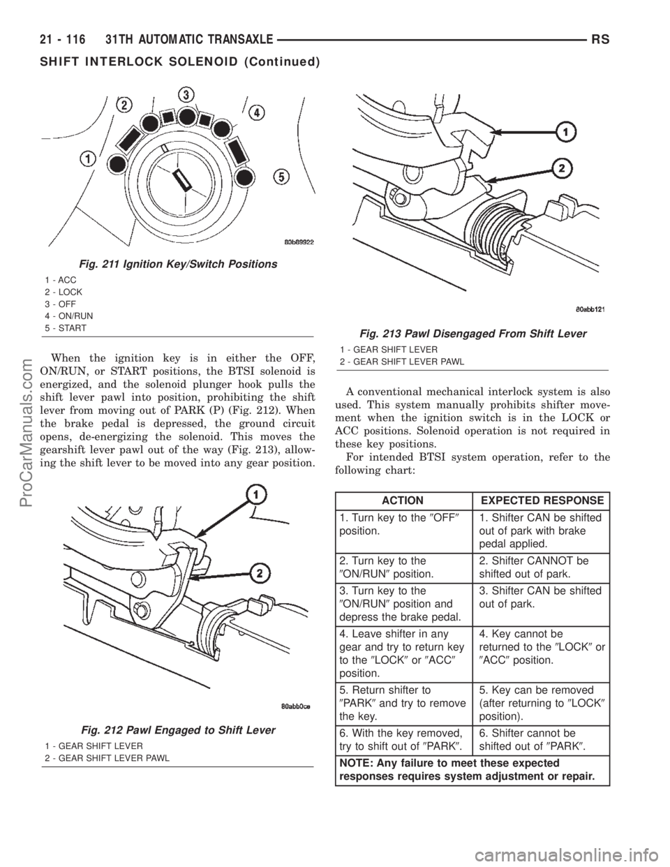
When the ignition key is in either the OFF,
ON/RUN, or START positions, the BTSI solenoid is
energized, and the solenoid plunger hook pulls the
shift lever pawl into position, prohibiting the shift
lever from moving out of PARK (P) (Fig. 212). When
the brake pedal is depressed, the ground circuit
opens, de-energizing the solenoid. This moves the
gearshift lever pawl out of the way (Fig. 213), allow-
ing the shift lever to be moved into any gear position.A conventional mechanical interlock system is also
used. This system manually prohibits shifter move-
ment when the ignition switch is in the LOCK or
ACC positions. Solenoid operation is not required in
these key positions.
For intended BTSI system operation, refer to the
following chart:
ACTION EXPECTED RESPONSE
1. Turn key to the9OFF9
position.1. Shifter CAN be shifted
out of park with brake
pedal applied.
2. Turn key to the
9ON/RUN9position.2. Shifter CANNOT be
shifted out of park.
3. Turn key to the
9ON/RUN9position and
depress the brake pedal.3. Shifter CAN be shifted
out of park.
4. Leave shifter in any
gear and try to return key
to the9LOCK9or9ACC9
position.4. Key cannot be
returned to the9LOCK9or
9ACC9position.
5. Return shifter to
9PARK9and try to remove
the key.5. Key can be removed
(after returning to9LOCK9
position).
6. With the key removed,
try to shift out of9PARK9.6. Shifter cannot be
shifted out of9PARK9.
NOTE: Any failure to meet these expected
responses requires system adjustment or repair.
Fig. 211 Ignition Key/Switch Positions
1 - ACC
2 - LOCK
3 - OFF
4 - ON/RUN
5-START
Fig. 212 Pawl Engaged to Shift Lever
1 - GEAR SHIFT LEVER
2 - GEAR SHIFT LEVER PAWL
Fig. 213 Pawl Disengaged From Shift Lever
1 - GEAR SHIFT LEVER
2 - GEAR SHIFT LEVER PAWL
21 - 116 31TH AUTOMATIC TRANSAXLERS
SHIFT INTERLOCK SOLENOID (Continued)
ProCarManuals.com
Page 1811 of 2399
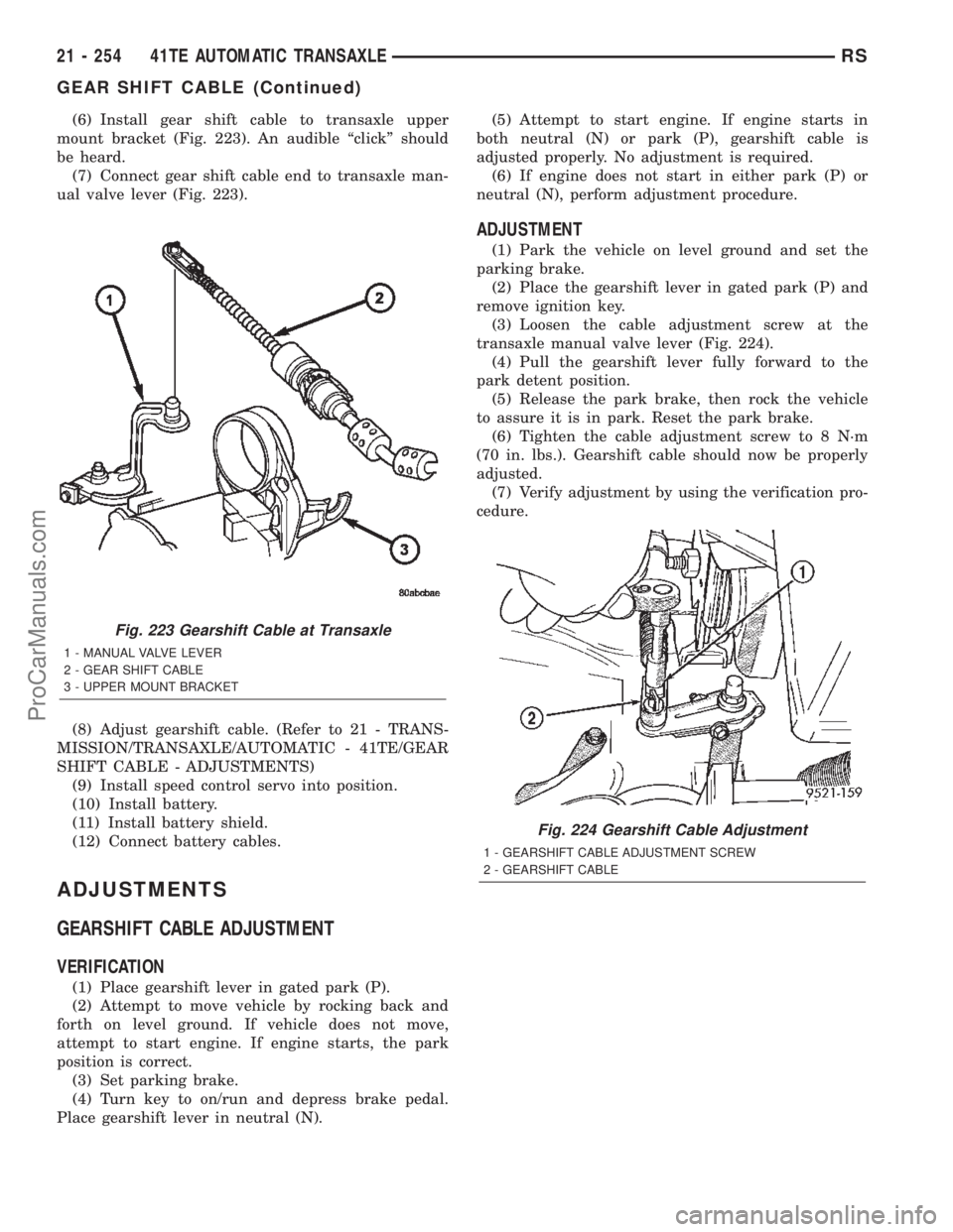
(6) Install gear shift cable to transaxle upper
mount bracket (Fig. 223). An audible ªclickº should
be heard.
(7) Connect gear shift cable end to transaxle man-
ual valve lever (Fig. 223).
(8) Adjust gearshift cable. (Refer to 21 - TRANS-
MISSION/TRANSAXLE/AUTOMATIC - 41TE/GEAR
SHIFT CABLE - ADJUSTMENTS)
(9) Install speed control servo into position.
(10) Install battery.
(11) Install battery shield.
(12) Connect battery cables.
ADJUSTMENTS
GEARSHIFT CABLE ADJUSTMENT
VERIFICATION
(1) Place gearshift lever in gated park (P).
(2) Attempt to move vehicle by rocking back and
forth on level ground. If vehicle does not move,
attempt to start engine. If engine starts, the park
position is correct.
(3) Set parking brake.
(4) Turn key to on/run and depress brake pedal.
Place gearshift lever in neutral (N).(5) Attempt to start engine. If engine starts in
both neutral (N) or park (P), gearshift cable is
adjusted properly. No adjustment is required.
(6) If engine does not start in either park (P) or
neutral (N), perform adjustment procedure.
ADJUSTMENT
(1) Park the vehicle on level ground and set the
parking brake.
(2) Place the gearshift lever in gated park (P) and
remove ignition key.
(3) Loosen the cable adjustment screw at the
transaxle manual valve lever (Fig. 224).
(4) Pull the gearshift lever fully forward to the
park detent position.
(5) Release the park brake, then rock the vehicle
to assure it is in park. Reset the park brake.
(6) Tighten the cable adjustment screw to 8 N´m
(70 in. lbs.). Gearshift cable should now be properly
adjusted.
(7) Verify adjustment by using the verification pro-
cedure.
Fig. 223 Gearshift Cable at Transaxle
1 - MANUAL VALVE LEVER
2 - GEAR SHIFT CABLE
3 - UPPER MOUNT BRACKET
Fig. 224 Gearshift Cable Adjustment
1 - GEARSHIFT CABLE ADJUSTMENT SCREW
2 - GEARSHIFT CABLE
21 - 254 41TE AUTOMATIC TRANSAXLERS
GEAR SHIFT CABLE (Continued)
ProCarManuals.com
Page 1833 of 2399
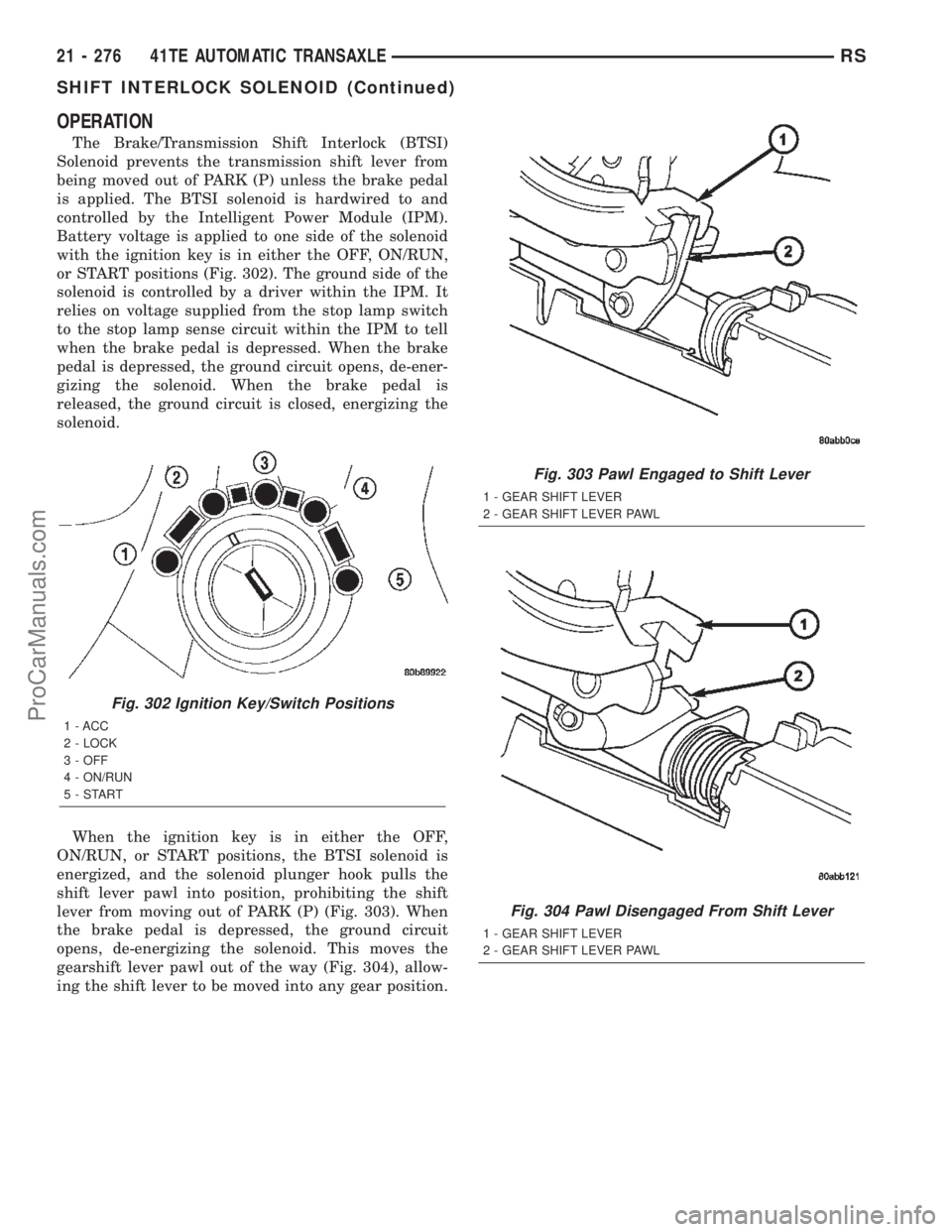
OPERATION
The Brake/Transmission Shift Interlock (BTSI)
Solenoid prevents the transmission shift lever from
being moved out of PARK (P) unless the brake pedal
is applied. The BTSI solenoid is hardwired to and
controlled by the Intelligent Power Module (IPM).
Battery voltage is applied to one side of the solenoid
with the ignition key is in either the OFF, ON/RUN,
or START positions (Fig. 302). The ground side of the
solenoid is controlled by a driver within the IPM. It
relies on voltage supplied from the stop lamp switch
to the stop lamp sense circuit within the IPM to tell
when the brake pedal is depressed. When the brake
pedal is depressed, the ground circuit opens, de-ener-
gizing the solenoid. When the brake pedal is
released, the ground circuit is closed, energizing the
solenoid.
When the ignition key is in either the OFF,
ON/RUN, or START positions, the BTSI solenoid is
energized, and the solenoid plunger hook pulls the
shift lever pawl into position, prohibiting the shift
lever from moving out of PARK (P) (Fig. 303). When
the brake pedal is depressed, the ground circuit
opens, de-energizing the solenoid. This moves the
gearshift lever pawl out of the way (Fig. 304), allow-
ing the shift lever to be moved into any gear position.
Fig. 302 Ignition Key/Switch Positions
1 - ACC
2 - LOCK
3 - OFF
4 - ON/RUN
5-START
Fig. 303 Pawl Engaged to Shift Lever
1 - GEAR SHIFT LEVER
2 - GEAR SHIFT LEVER PAWL
Fig. 304 Pawl Disengaged From Shift Lever
1 - GEAR SHIFT LEVER
2 - GEAR SHIFT LEVER PAWL
21 - 276 41TE AUTOMATIC TRANSAXLERS
SHIFT INTERLOCK SOLENOID (Continued)
ProCarManuals.com
Page 1834 of 2399
A conventional mechanical interlock system is also
used. This system manually prohibits shifter move-
ment when the ignition switch is in the LOCK or
ACC positions. Solenoid operation is not required in
these key positions.
For intended BTSI system operation, refer to the
following chart:
ACTION EXPECTED RESPONSE
1. Turn key to the9OFF9
position.1. Shifter CAN be shifted
out of park with brake
pedal applied.
2. Turn key to the
9ON/RUN9position.2. Shifter CANNOT be
shifted out of park.
3. Turn key to the
9ON/RUN9position and
depress the brake pedal.3. Shifter CAN be shifted
out of park.
4. Leave shifter in any
gear and try to return key
to the9LOCK9or9ACC9
position.4. Key cannot be
returned to the9LOCK9or
9ACC9position.
5. Return shifter to
9PARK9and try to remove
the key.5. Key can be removed
(after returning to9LOCK9
position).
6. With the key removed,
try to shift out of9PARK9.6. Shifter cannot be
shifted out of9PARK9.
NOTE: Any failure to meet these expected
responses requires system adjustment or repair.
DIAGNOSIS AND TESTING - BRAKE/
TRANSMISSION SHIFT INTERLOCK SOLENOID
For intended BTSI system operation, refer to the
following chart:
ACTION EXPECTED RESPONSE
1. Turn key to the9OFF9
position.1. Shifter CAN be shifted
out of park with brake
pedal applied.
2. Turn key to the
9ON/RUN9position.2. Shifter CANNOT be
shifted out of park.
3. Turn key to the
9ON/RUN9position and
depress the brake pedal.3. Shifter CAN be shifted
out of park.
4. Leave shifter in any
gear and try to return key
to the9LOCK9or9ACC9
position.4. Key cannot be
returned to the9LOCK9or
9ACC9position.
5. Return shifter to
9PARK9and try to remove
the key.5. Key can be removed
(after returning to9LOCK9
position).
ACTION EXPECTED RESPONSE
6. With the key removed,
try to shift out of9PARK9.6. Shifter cannot be
shifted out of9PARK9.
NOTE: Any failure to meet these expected
responses requires system repair. Refer to the
appropriate Diagnostic Information.
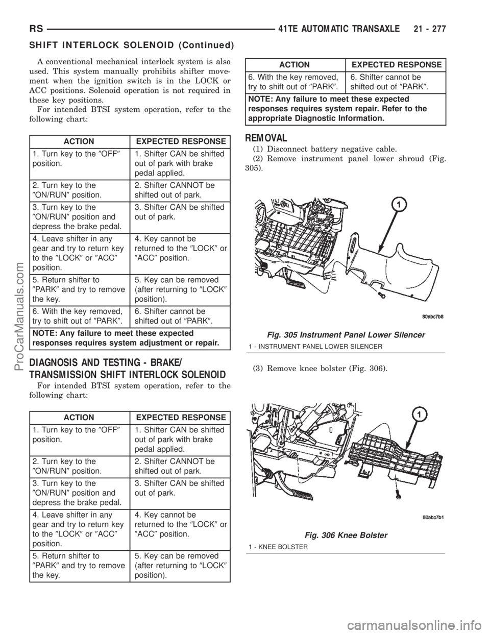
REMOVAL
(1) Disconnect battery negative cable.
(2) Remove instrument panel lower shroud (Fig.
305).
(3) Remove knee bolster (Fig. 306).
Fig. 305 Instrument Panel Lower Silencer
1 - INSTRUMENT PANEL LOWER SILENCER
Fig. 306 Knee Bolster
1 - KNEE BOLSTER
RS41TE AUTOMATIC TRANSAXLE21 - 277
SHIFT INTERLOCK SOLENOID (Continued)
ProCarManuals.com
Page 1848 of 2399
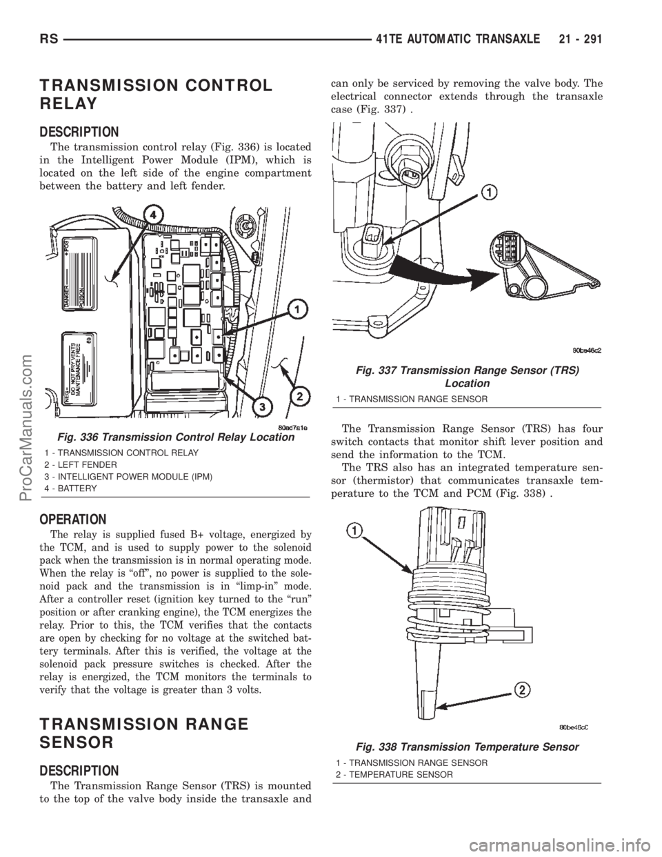
TRANSMISSION CONTROL
RELAY
DESCRIPTION
The transmission control relay (Fig. 336) is located
in the Intelligent Power Module (IPM), which is
located on the left side of the engine compartment
between the battery and left fender.
OPERATION
The relay is supplied fused B+ voltage, energized by
the TCM, and is used to supply power to the solenoid
pack when the transmission is in normal operating mode.
When the relay is ªoffº, no power is supplied to the sole-
noid pack and the transmission is in ªlimp-inº mode.
After a controller reset (ignition key turned to the ªrunº
position or after cranking engine), the TCM energizes the
relay. Prior to this, the TCM verifies that the contacts
are open by checking for no voltage at the switched bat-
tery terminals. After this is verified, the voltage at the
solenoid pack pressure switches is checked. After the
relay is energized, the TCM monitors the terminals to
verify that the voltage is greater than 3 volts.
TRANSMISSION RANGE
SENSOR
DESCRIPTION
The Transmission Range Sensor (TRS) is mounted
to the top of the valve body inside the transaxle andcan only be serviced by removing the valve body. The
electrical connector extends through the transaxle
case (Fig. 337) .
The Transmission Range Sensor (TRS) has four
switch contacts that monitor shift lever position and
send the information to the TCM.
The TRS also has an integrated temperature sen-
sor (thermistor) that communicates transaxle tem-
perature to the TCM and PCM (Fig. 338) .
Fig. 336 Transmission Control Relay Location
1 - TRANSMISSION CONTROL RELAY
2 - LEFT FENDER
3 - INTELLIGENT POWER MODULE (IPM)
4 - BATTERY
Fig. 337 Transmission Range Sensor (TRS)
Location
1 - TRANSMISSION RANGE SENSOR
Fig. 338 Transmission Temperature Sensor
1 - TRANSMISSION RANGE SENSOR
2 - TEMPERATURE SENSOR
RS41TE AUTOMATIC TRANSAXLE21 - 291
ProCarManuals.com
Page 1850 of 2399
is requested when the TCM pulses this signal to
ground. The PCM recognizes this request and
responds by retarding ignition timing, killing fuel
injectors, etc. The PCM sends a confirmation of the
request to the TCM via the communication bus.
Torque reduction is not noticable by the driver, and
usually lasts for a very short period of time.
If the confirmation signal is not received by the
TCM after two sequential request messages, a diag-
nostic trouble code will be set.
VALVE BODY
DESCRIPTION
The valve body assembly consists of a cast alumi-
num valve body, a separator plate, and transfer
plate. The valve body contains valves and check balls
that control fluid delivery to the torque converter
clutch, solenoid/pressure switch assembly, and fric-
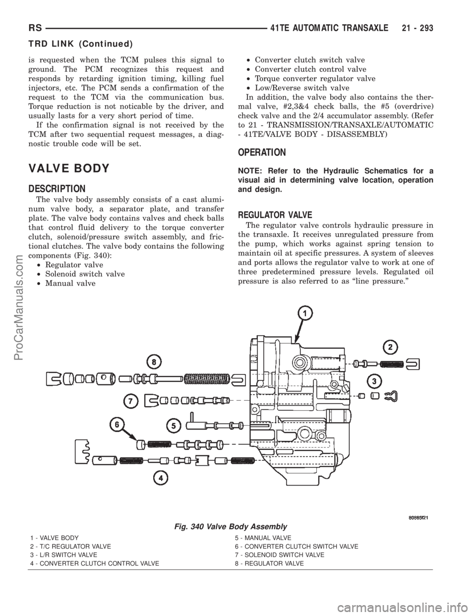
tional clutches. The valve body contains the following
components (Fig. 340):
²Regulator valve
²Solenoid switch valve
²Manual valve²Converter clutch switch valve
²Converter clutch control valve
²Torque converter regulator valve
²Low/Reverse switch valve
In addition, the valve body also contains the ther-
mal valve, #2,3&4 check balls, the #5 (overdrive)
check valve and the 2/4 accumulator assembly. (Refer
to 21 - TRANSMISSION/TRANSAXLE/AUTOMATIC
- 41TE/VALVE BODY - DISASSEMBLY)
OPERATION
NOTE: Refer to the Hydraulic Schematics for a
visual aid in determining valve location, operation
and design.
REGULATOR VALVE
The regulator valve controls hydraulic pressure in
the transaxle. It receives unregulated pressure from
the pump, which works against spring tension to
maintain oil at specific pressures. A system of sleeves
and ports allows the regulator valve to work at one of
three predetermined pressure levels. Regulated oil
pressure is also referred to as ªline pressure.º
Fig. 340 Valve Body Assembly
1 - VALVE BODY 5 - MANUAL VALVE
2 - T/C REGULATOR VALVE 6 - CONVERTER CLUTCH SWITCH VALVE
3 - L/R SWITCH VALVE 7 - SOLENOID SWITCH VALVE
4 - CONVERTER CLUTCH CONTROL VALVE 8 - REGULATOR VALVE
RS41TE AUTOMATIC TRANSAXLE21 - 293
TRD LINK (Continued)
ProCarManuals.com
Page 1970 of 2399
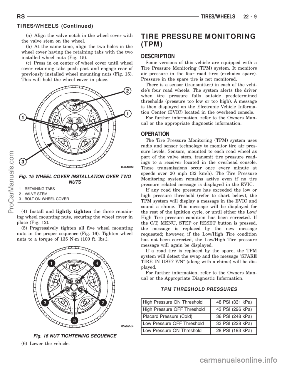
(a) Align the valve notch in the wheel cover with
the valve stem on the wheel.
(b) At the same time, align the two holes in the
wheel cover having the retaining tabs with the two
installed wheel nuts (Fig. 15).
(c) Press in on center of wheel cover until wheel
cover retaining tabs push past and engage rear of
previously installed wheel mounting nuts (Fig. 15).
This will hold the wheel cover in place.
(4) Install andlightly tightenthe three remain-
ing wheel mounting nuts, securing the wheel cover in
place (Fig. 12).
(5) Progressively tighten all five wheel mounting
nuts in the proper sequence (Fig. 16). Tighten wheel
nuts to a torque of 135 N´m (100 ft. lbs.).
(6) Lower the vehicle.TIRE PRESSURE MONITORING
(TPM)
DESCRIPTION
Some versions of this vehicle are equipped with a
Tire Pressure Monitoring (TPM) system. It monitors
air pressure in the four road tires (excludes spare).
Pressure in the spare tire is not monitored.
There is a sensor (transmitter) in each of the vehi-
cle's four road wheels. The system alerts the driver
when tire pressure falls outside predetermined
thresholds (pressure too low or too high). A message
is then displayed on the Electronic Vehicle Informa-
tion Center (EVIC) located in the overhead console.
For further information, refer to the Owners Man-
ual or the appropriate diagnostic information.
OPERATION
The Tire Pressure Monitoring (TPM) system uses
radio and sensor technology to monitor tire air pres-
sure levels. Sensors, mounted to each road wheel as
part of the valve stem, transmit tire pressure read-
ings to a receiver located in the overhead console.
These transmissions occur once every minute at
speeds over 20 mph (32 km/h). The Tire Pressure
Monitoring system remains active even if no tire
pressure related message is displayed in the EVIC.
If any road tire pressure has exceeded the low or
high pressure threshold (refer to chart below), the
TPM system will display a message in the EVIC and
sound a chime. This message will be displayed for
the rest of the ignition cycle, or until either the Low/
High Tire pressure condition has been corrected. If
the C/T, MENU, STEP or RESET button is pressed,
the message is replaced by the new message
requested; however, if the Low/High Tire condition
has not been corrected, the Low/High Tire pressure
message will again be displayed.
If a road tire is replaced by the spare, the TPM
system will detect the swap and the message9SPARE
TIRE IN USE? Y/N9(along with a chime) will be dis-
played.
For further information, refer to the Owners Man-
ual or the Appropriate Diagnostic Information.
TPM THRESHOLD PRESSURES
High Pressure ON Threshold 48 PSI (331 kPa)
High Pressure OFF Threshold 43 PSI (296 kPa)
Placard Pressure (Cold) 36 PSI (248 kPa)
Low Pressure OFF Threshold 33 PSI (228 kPa)
Low Pressure ON Threshold 28 PSI (193 kPa)
Fig. 15 WHEEL COVER INSTALLATION OVER TWO
NUTS
1 - RETAINING TABS
2 - VALVE STEM
3 - BOLT-ON WHEEL COVER
Fig. 16 NUT TIGHTENING SEQUENCE
RSTIRES/WHEELS22-9
TIRES/WHEELS (Continued)
ProCarManuals.com