torque CHRYSLER VOYAGER 2002 Service Manual
[x] Cancel search | Manufacturer: CHRYSLER, Model Year: 2002, Model line: VOYAGER, Model: CHRYSLER VOYAGER 2002Pages: 2399, PDF Size: 57.96 MB
Page 1614 of 2399
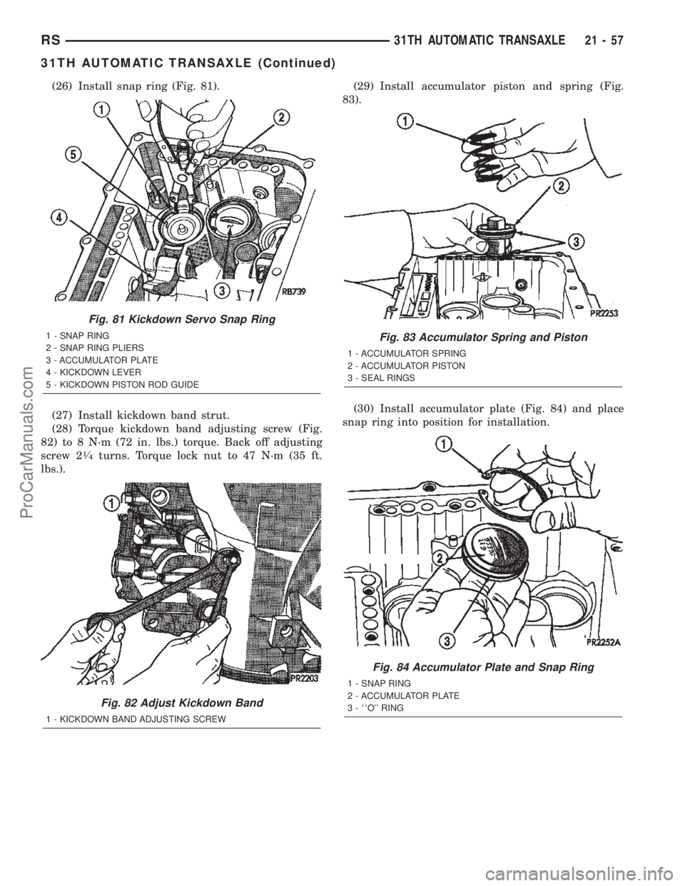
(26) Install snap ring (Fig. 81).
(27) Install kickdown band strut.
(28) Torque kickdown band adjusting screw (Fig.
82) to 8 N´m (72 in. lbs.) torque. Back off adjusting
screw 2
1¤4turns. Torque lock nut to 47 N´m (35 ft.
lbs.).(29) Install accumulator piston and spring (Fig.
83).
(30) Install accumulator plate (Fig. 84) and place
snap ring into position for installation.
Fig. 81 Kickdown Servo Snap Ring
1 - SNAP RING
2 - SNAP RING PLIERS
3 - ACCUMULATOR PLATE
4 - KICKDOWN LEVER
5 - KICKDOWN PISTON ROD GUIDE
Fig. 82 Adjust Kickdown Band
1 - KICKDOWN BAND ADJUSTING SCREW
Fig. 83 Accumulator Spring and Piston
1 - ACCUMULATOR SPRING
2 - ACCUMULATOR PISTON
3 - SEAL RINGS
Fig. 84 Accumulator Plate and Snap Ring
1 - SNAP RING
2 - ACCUMULATOR PLATE
3-88O'' RING
RS31TH AUTOMATIC TRANSAXLE21-57
31TH AUTOMATIC TRANSAXLE (Continued)
ProCarManuals.com
Page 1615 of 2399
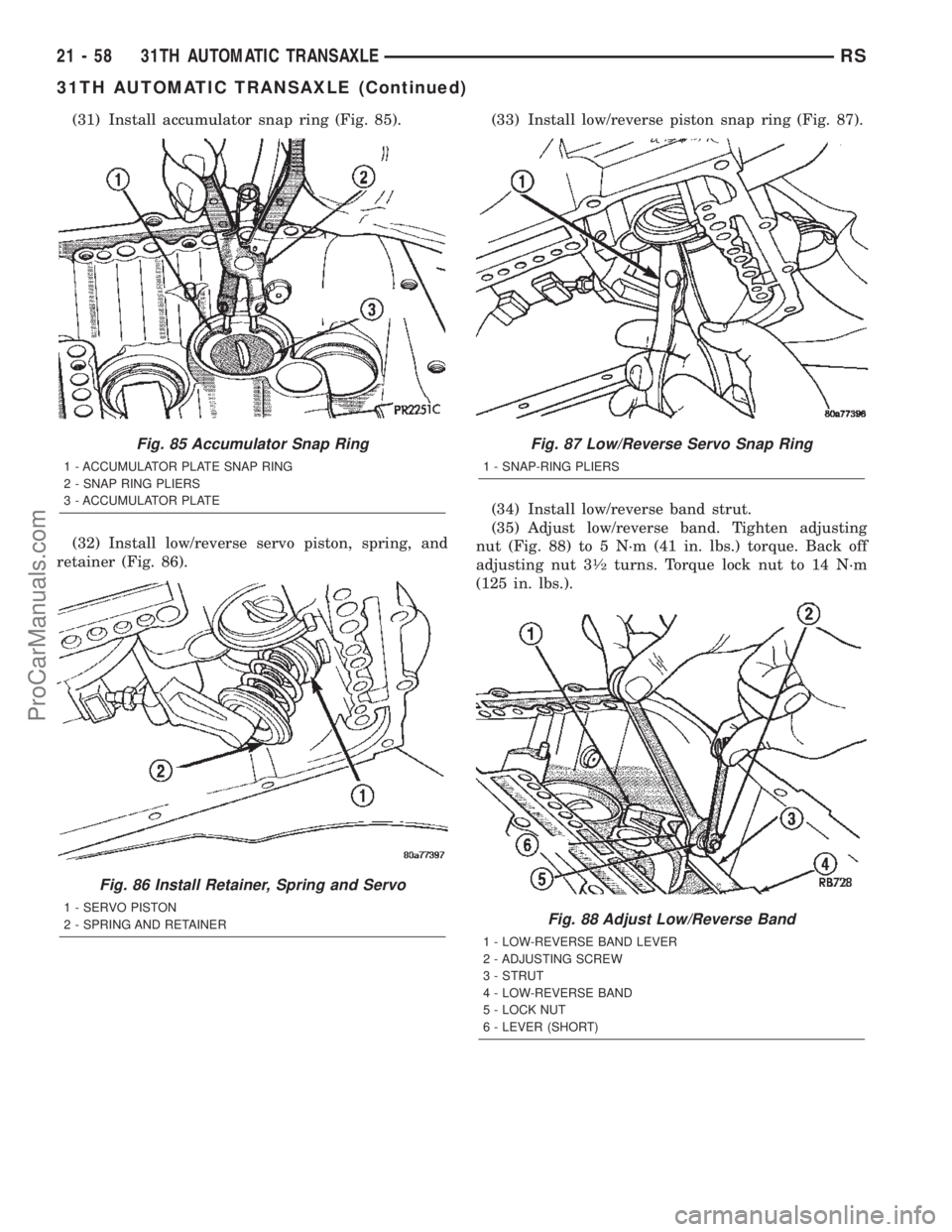
(31) Install accumulator snap ring (Fig. 85).
(32) Install low/reverse servo piston, spring, and
retainer (Fig. 86).(33) Install low/reverse piston snap ring (Fig. 87).
(34) Install low/reverse band strut.
(35) Adjust low/reverse band. Tighten adjusting
nut (Fig. 88) to 5 N´m (41 in. lbs.) torque. Back off
adjusting nut 3
1¤2turns. Torque lock nut to 14 N´m
(125 in. lbs.).
Fig. 85 Accumulator Snap Ring
1 - ACCUMULATOR PLATE SNAP RING
2 - SNAP RING PLIERS
3 - ACCUMULATOR PLATE
Fig. 86 Install Retainer, Spring and Servo
1 - SERVO PISTON
2 - SPRING AND RETAINER
Fig. 87 Low/Reverse Servo Snap Ring
1 - SNAP-RING PLIERS
Fig. 88 Adjust Low/Reverse Band
1 - LOW-REVERSE BAND LEVER
2 - ADJUSTING SCREW
3 - STRUT
4 - LOW-REVERSE BAND
5 - LOCK NUT
6 - LEVER (SHORT)
21 - 58 31TH AUTOMATIC TRANSAXLERS
31TH AUTOMATIC TRANSAXLE (Continued)
ProCarManuals.com
Page 1616 of 2399
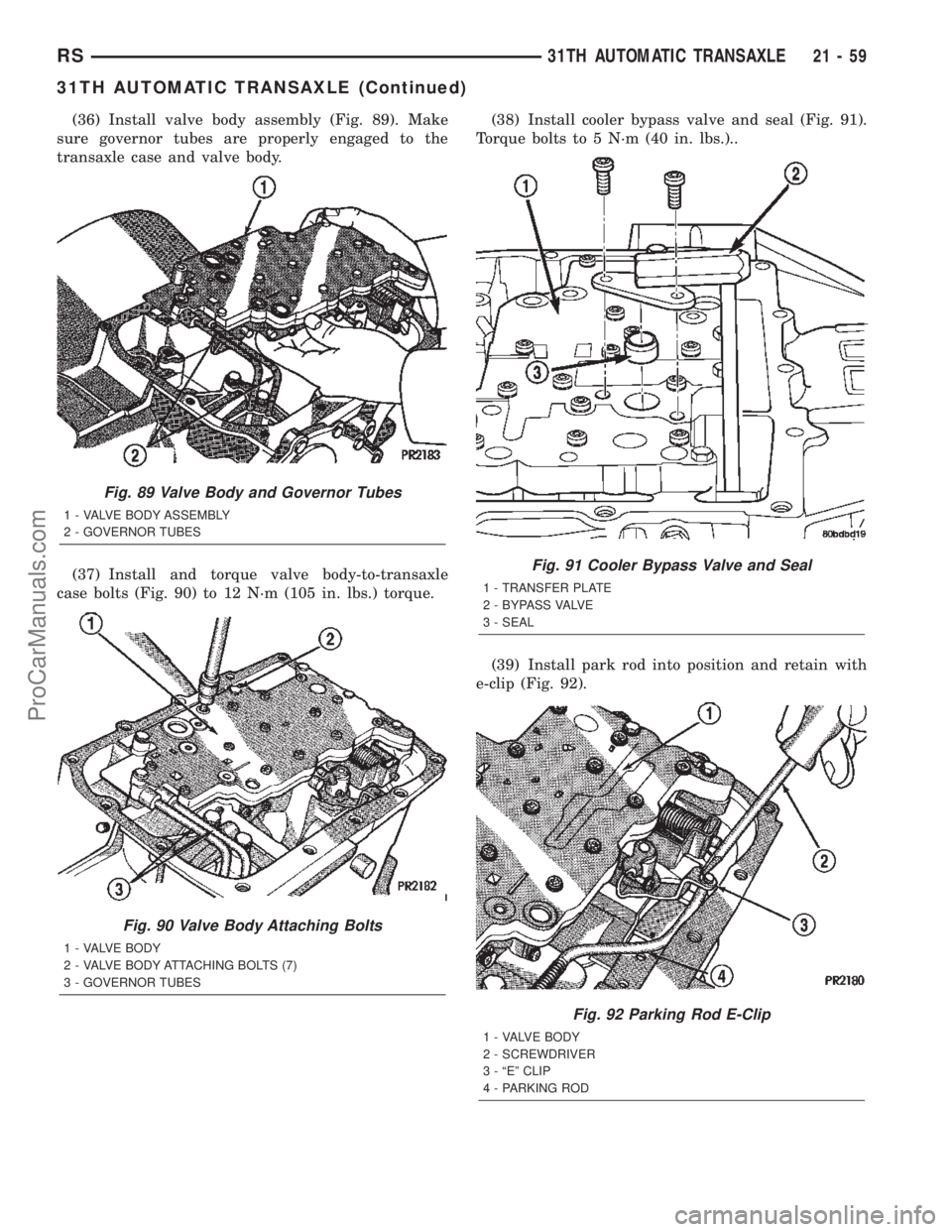
(36) Install valve body assembly (Fig. 89). Make
sure governor tubes are properly engaged to the
transaxle case and valve body.
(37) Install and torque valve body-to-transaxle
case bolts (Fig. 90) to 12 N´m (105 in. lbs.) torque.(38) Install cooler bypass valve and seal (Fig. 91).
Torque bolts to 5 N´m (40 in. lbs.)..
(39) Install park rod into position and retain with
e-clip (Fig. 92).
Fig. 89 Valve Body and Governor Tubes
1 - VALVE BODY ASSEMBLY
2 - GOVERNOR TUBES
Fig. 90 Valve Body Attaching Bolts
1 - VALVE BODY
2 - VALVE BODY ATTACHING BOLTS (7)
3 - GOVERNOR TUBES
Fig. 91 Cooler Bypass Valve and Seal
1 - TRANSFER PLATE
2 - BYPASS VALVE
3 - SEAL
Fig. 92 Parking Rod E-Clip
1 - VALVE BODY
2 - SCREWDRIVER
3 - ªEº CLIP
4 - PARKING ROD
RS31TH AUTOMATIC TRANSAXLE21-59
31TH AUTOMATIC TRANSAXLE (Continued)
ProCarManuals.com
Page 1617 of 2399
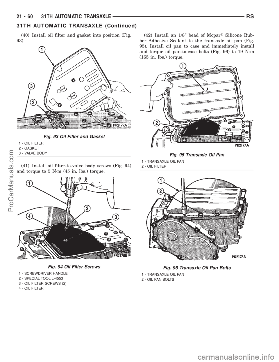
(40) Install oil filter and gasket into position (Fig.
93).
(41) Install oil filter-to-valve body screws (Fig. 94)
and torque to 5 N´m (45 in. lbs.) torque.(42) Install an 1/8º bead of MopartSilicone Rub-
ber Adhesive Sealant to the transaxle oil pan (Fig.
95). Install oil pan to case and immediately install
and torque oil pan-to-case bolts (Fig. 96) to 19 N´m
(165 in. lbs.) torque.
Fig. 93 Oil Filter and Gasket
1 - OIL FILTER
2 - GASKET
3 - VALVE BODY
Fig. 94 Oil Filter Screws
1 - SCREWDRIVER HANDLE
2 - SPECIAL TOOL L-4553
3 - OIL FILTER SCREWS (2)
4 - OIL FILTER
Fig. 95 Transaxle Oil Pan
1 - TRANSAXLE OIL PAN
2 - OIL FILTER
Fig. 96 Transaxle Oil Pan Bolts
1 - TRANSAXLE OIL PAN
2 - OIL PAN BOLTS
21 - 60 31TH AUTOMATIC TRANSAXLERS
31TH AUTOMATIC TRANSAXLE (Continued)
ProCarManuals.com
Page 1618 of 2399
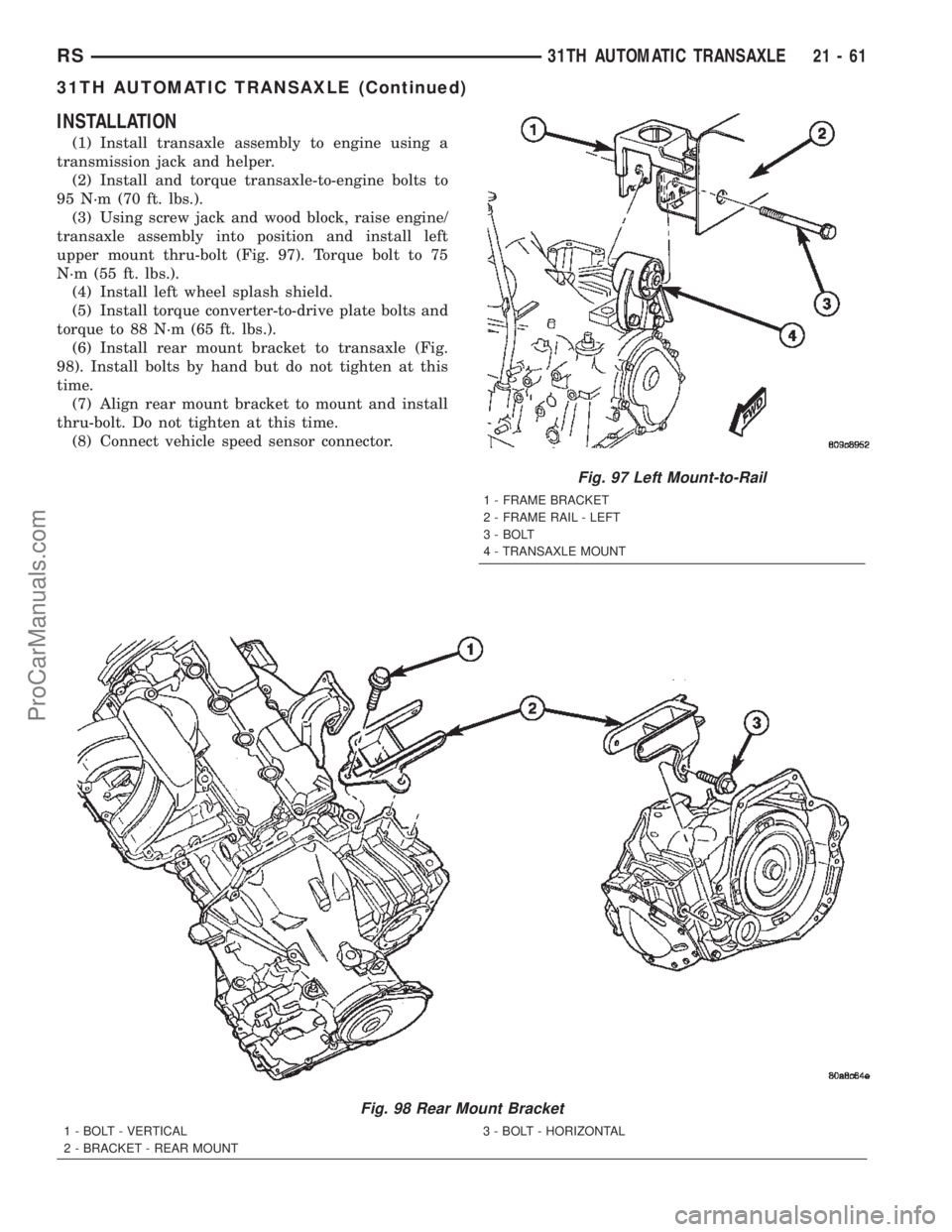
INSTALLATION
(1) Install transaxle assembly to engine using a
transmission jack and helper.
(2) Install and torque transaxle-to-engine bolts to
95 N´m (70 ft. lbs.).
(3) Using screw jack and wood block, raise engine/
transaxle assembly into position and install left
upper mount thru-bolt (Fig. 97). Torque bolt to 75
N´m (55 ft. lbs.).
(4) Install left wheel splash shield.
(5) Install torque converter-to-drive plate bolts and
torque to 88 N´m (65 ft. lbs.).
(6) Install rear mount bracket to transaxle (Fig.
98). Install bolts by hand but do not tighten at this
time.
(7) Align rear mount bracket to mount and install
thru-bolt. Do not tighten at this time.
(8) Connect vehicle speed sensor connector.
Fig. 97 Left Mount-to-Rail
1 - FRAME BRACKET
2 - FRAME RAIL - LEFT
3 - BOLT
4 - TRANSAXLE MOUNT
Fig. 98 Rear Mount Bracket
1 - BOLT - VERTICAL
2 - BRACKET - REAR MOUNT3 - BOLT - HORIZONTAL
RS31TH AUTOMATIC TRANSAXLE21-61
31TH AUTOMATIC TRANSAXLE (Continued)
ProCarManuals.com
Page 1620 of 2399
(13) Install halfshafts. (Refer to 3 - DIFFEREN-
TIAL & DRIVELINE/HALF SHAFT - INSTALLA-
TION)
(14) Lower vehicle.
(15) Torque rear mount bracket-to-transaxle verti-
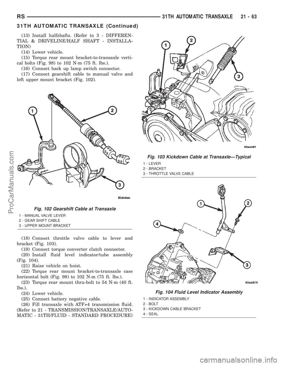
cal bolts (Fig. 98) to 102 N´m (75 ft. lbs.).
(16) Connect back up lamp switch connector.
(17) Connect gearshift cable to manual valve and
left upper mount bracket (Fig. 102).
(18) Connect throttle valve cable to lever and
bracket (Fig. 103).
(19) Connect torque converter clutch connector.
(20) Install fluid level indicator/tube assembly
(Fig. 104).
(21) Raise vehicle on hoist.
(22) Torque rear mount bracket-to-transaxle case
horizontal bolt (Fig. 98) to 102 N´m (75 ft. lbs.).
(23) Torque rear mount thru-bolt to 54 N´m (40 ft.
lbs.).
(24) Lower vehicle.
(25) Connect battery negative cable.
(26) Fill transaxle with ATF+4 transmission fluid.
(Refer to 21 - TRANSMISSION/TRANSAXLE/AUTO-
MATIC - 31TH/FLUID - STANDARD PROCEDURE)
Fig. 102 Gearshift Cable at Transaxle
1 - MANUAL VALVE LEVER
2 - GEAR SHIFT CABLE
3 - UPPER MOUNT BRACKET
Fig. 103 Kickdown Cable at TransaxleÐTypical
1 - LEVER
2 - BRACKET
3 - THROTTLE VALVE CABLE
Fig. 104 Fluid Level Indicator Assembly
1 - INDICATOR ASSEMBLY
2 - BOLT
3 - KICKDOWN CABLE BRACKET
4 - SEAL
RS31TH AUTOMATIC TRANSAXLE21-63
31TH AUTOMATIC TRANSAXLE (Continued)
ProCarManuals.com
Page 1629 of 2399
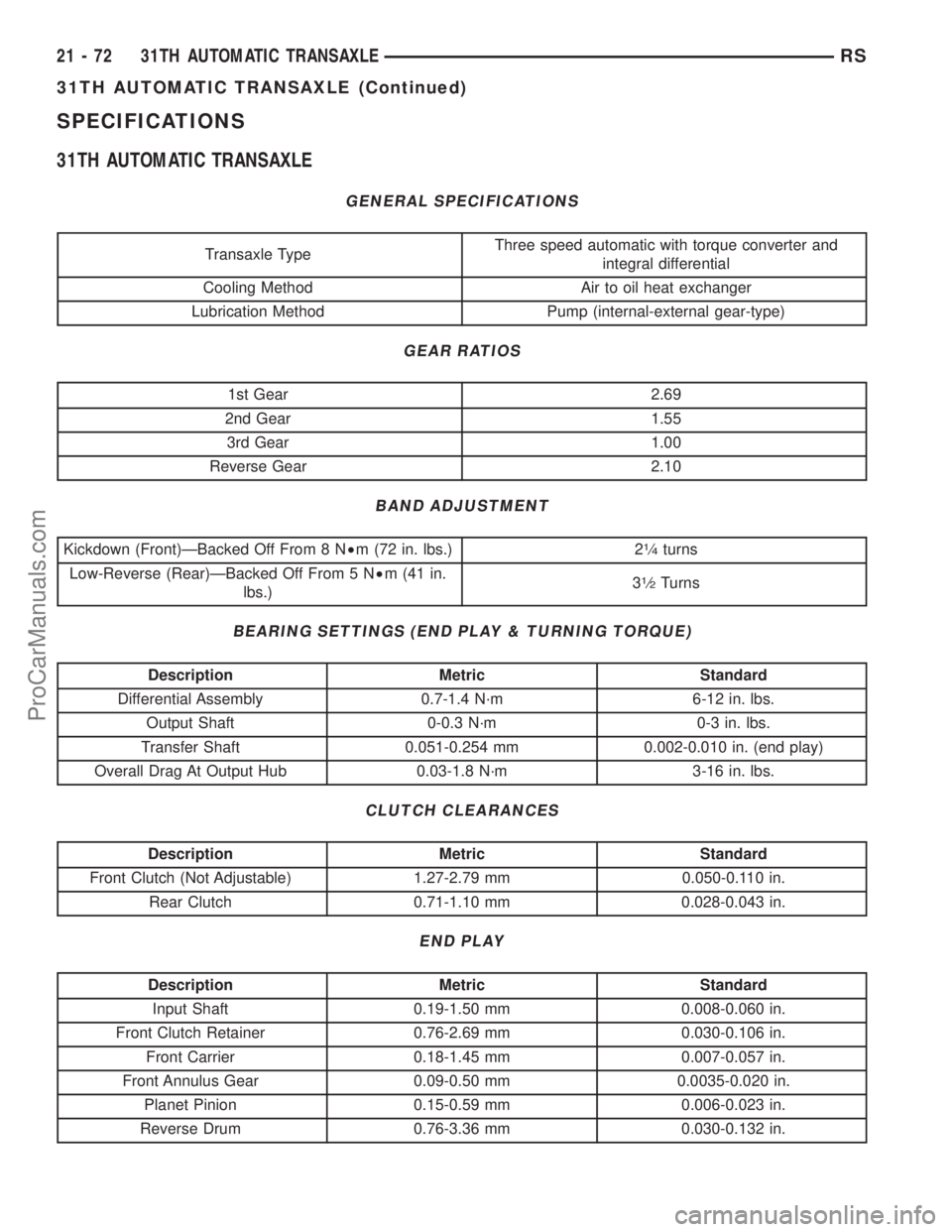
SPECIFICATIONS
31TH AUTOMATIC TRANSAXLE
GENERAL SPECIFICATIONS
Transaxle TypeThree speed automatic with torque converter and
integral differential
Cooling Method Air to oil heat exchanger
Lubrication Method Pump (internal-external gear-type)
GEAR RATIOS
1st Gear 2.69
2nd Gear 1.55
3rd Gear 1.00
Reverse Gear 2.10
BAND ADJUSTMENT
Kickdown (Front)ÐBacked Off From 8 N²m (72 in. lbs.) 21¤4turns
Low-Reverse (Rear)ÐBacked Off From 5 N²m (41 in.
lbs.)3
1¤2Turns
BEARING SETTINGS (END PLAY & TURNING TORQUE)
Description Metric Standard
Differential Assembly 0.7-1.4 N´m 6-12 in. lbs.
Output Shaft 0-0.3 N´m 0-3 in. lbs.
Transfer Shaft 0.051-0.254 mm 0.002-0.010 in. (end play)
Overall Drag At Output Hub 0.03-1.8 N´m 3-16 in. lbs.
CLUTCH CLEARANCES
Description Metric Standard
Front Clutch (Not Adjustable) 1.27-2.79 mm 0.050-0.110 in.
Rear Clutch 0.71-1.10 mm 0.028-0.043 in.
END PLAY
Description Metric Standard
Input Shaft 0.19-1.50 mm 0.008-0.060 in.
Front Clutch Retainer 0.76-2.69 mm 0.030-0.106 in.
Front Carrier 0.18-1.45 mm 0.007-0.057 in.
Front Annulus Gear 0.09-0.50 mm 0.0035-0.020 in.
Planet Pinion 0.15-0.59 mm 0.006-0.023 in.
Reverse Drum 0.76-3.36 mm 0.030-0.132 in.
21 - 72 31TH AUTOMATIC TRANSAXLERS
31TH AUTOMATIC TRANSAXLE (Continued)
ProCarManuals.com
Page 1631 of 2399
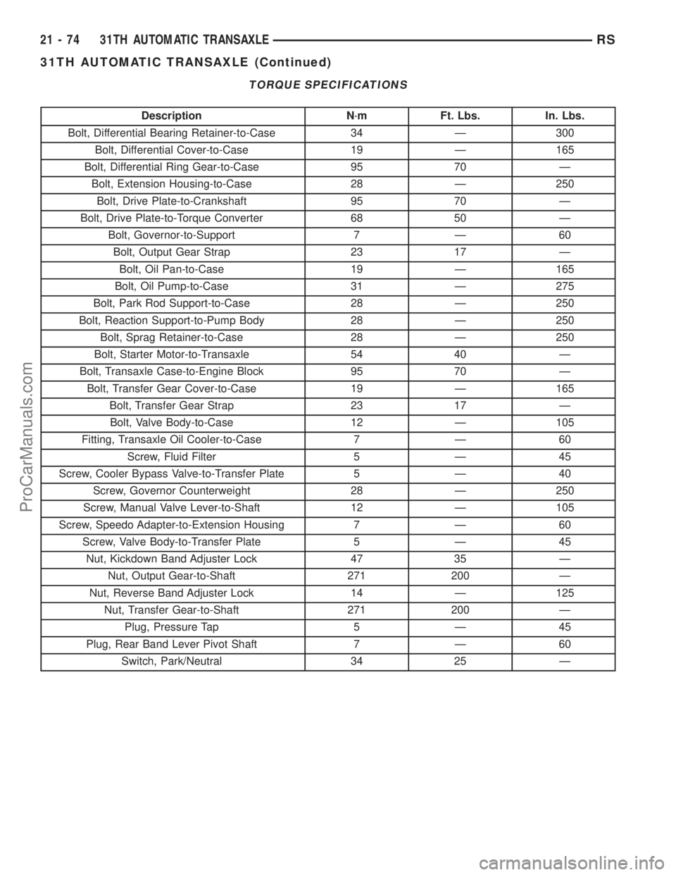
TORQUE SPECIFICATIONS
Description N´m Ft. Lbs. In. Lbs.
Bolt, Differential Bearing Retainer-to-Case 34 Ð 300
Bolt, Differential Cover-to-Case 19 Ð 165
Bolt, Differential Ring Gear-to-Case 95 70 Ð
Bolt, Extension Housing-to-Case 28 Ð 250
Bolt, Drive Plate-to-Crankshaft 95 70 Ð
Bolt, Drive Plate-to-Torque Converter 68 50 Ð
Bolt, Governor-to-Support 7 Ð 60
Bolt, Output Gear Strap 23 17 Ð
Bolt, Oil Pan-to-Case 19 Ð 165
Bolt, Oil Pump-to-Case 31 Ð 275
Bolt, Park Rod Support-to-Case 28 Ð 250
Bolt, Reaction Support-to-Pump Body 28 Ð 250
Bolt, Sprag Retainer-to-Case 28 Ð 250
Bolt, Starter Motor-to-Transaxle 54 40 Ð
Bolt, Transaxle Case-to-Engine Block 95 70 Ð
Bolt, Transfer Gear Cover-to-Case 19 Ð 165
Bolt, Transfer Gear Strap 23 17 Ð
Bolt, Valve Body-to-Case 12 Ð 105
Fitting, Transaxle Oil Cooler-to-Case 7 Ð 60
Screw, Fluid Filter 5 Ð 45
Screw, Cooler Bypass Valve-to-Transfer Plate 5 Ð 40
Screw, Governor Counterweight 28 Ð 250
Screw, Manual Valve Lever-to-Shaft 12 Ð 105
Screw, Speedo Adapter-to-Extension Housing 7 Ð 60
Screw, Valve Body-to-Transfer Plate 5 Ð 45
Nut, Kickdown Band Adjuster Lock 47 35 Ð
Nut, Output Gear-to-Shaft 271 200 Ð
Nut, Reverse Band Adjuster Lock 14 Ð 125
Nut, Transfer Gear-to-Shaft 271 200 Ð
Plug, Pressure Tap 5 Ð 45
Plug, Rear Band Lever Pivot Shaft 7 Ð 60
Switch, Park/Neutral 34 25 Ð
21 - 74 31TH AUTOMATIC TRANSAXLERS
31TH AUTOMATIC TRANSAXLE (Continued)
ProCarManuals.com
Page 1633 of 2399
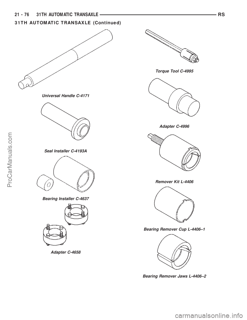
Universal Handle C-4171
Seal Installer C-4193A
Bearing Installer C-4637
Adapter C-4658
Torque Tool C-4995
Adapter C-4996
Remover Kit L-4406
Bearing Remover Cup L-4406±1
Bearing Remover Jaws L-4406±2
21 - 76 31TH AUTOMATIC TRANSAXLERS
31TH AUTOMATIC TRANSAXLE (Continued)
ProCarManuals.com
Page 1637 of 2399
BANDS
DESCRIPTION
KICKDOWN (FRONT) BAND
DESCRIPTION
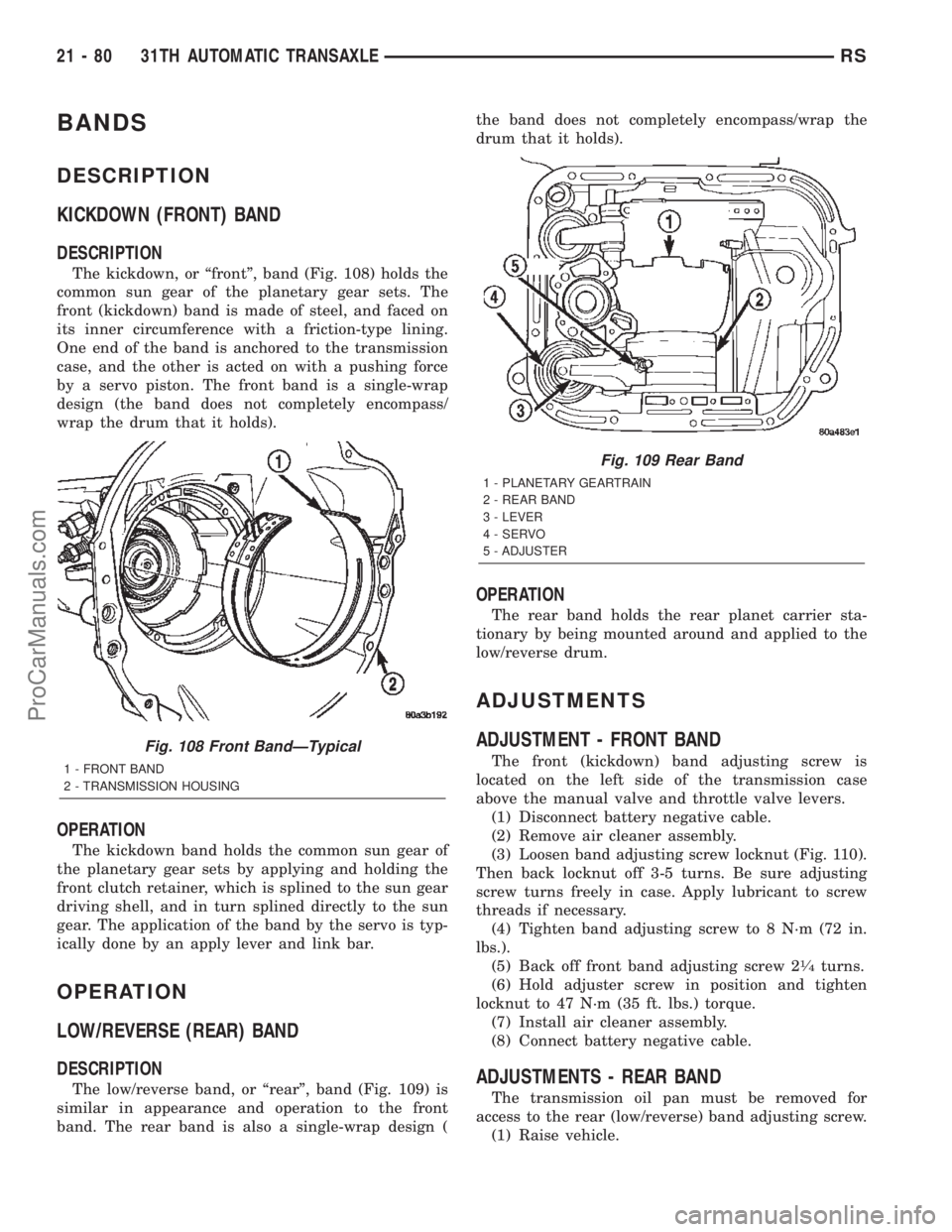
The kickdown, or ªfrontº, band (Fig. 108) holds the
common sun gear of the planetary gear sets. The
front (kickdown) band is made of steel, and faced on
its inner circumference with a friction-type lining.
One end of the band is anchored to the transmission
case, and the other is acted on with a pushing force
by a servo piston. The front band is a single-wrap
design (the band does not completely encompass/
wrap the drum that it holds).
OPERATION
The kickdown band holds the common sun gear of
the planetary gear sets by applying and holding the
front clutch retainer, which is splined to the sun gear
driving shell, and in turn splined directly to the sun
gear. The application of the band by the servo is typ-
ically done by an apply lever and link bar.
OPERATION
LOW/REVERSE (REAR) BAND
DESCRIPTION
The low/reverse band, or ªrearº, band (Fig. 109) is
similar in appearance and operation to the front
band. The rear band is also a single-wrap design (the band does not completely encompass/wrap the
drum that it holds).
OPERATION
The rear band holds the rear planet carrier sta-
tionary by being mounted around and applied to the
low/reverse drum.
ADJUSTMENTS
ADJUSTMENT - FRONT BAND
The front (kickdown) band adjusting screw is
located on the left side of the transmission case
above the manual valve and throttle valve levers.
(1) Disconnect battery negative cable.
(2) Remove air cleaner assembly.
(3) Loosen band adjusting screw locknut (Fig. 110).
Then back locknut off 3-5 turns. Be sure adjusting
screw turns freely in case. Apply lubricant to screw
threads if necessary.
(4) Tighten band adjusting screw to 8 N´m (72 in.
lbs.).
(5) Back off front band adjusting screw 2
1¤4turns.
(6) Hold adjuster screw in position and tighten
locknut to 47 N´m (35 ft. lbs.) torque.
(7) Install air cleaner assembly.
(8) Connect battery negative cable.
ADJUSTMENTS - REAR BAND
The transmission oil pan must be removed for
access to the rear (low/reverse) band adjusting screw.
(1) Raise vehicle.
Fig. 108 Front BandÐTypical
1 - FRONT BAND
2 - TRANSMISSION HOUSING
Fig. 109 Rear Band
1 - PLANETARY GEARTRAIN
2 - REAR BAND
3 - LEVER
4 - SERVO
5 - ADJUSTER
21 - 80 31TH AUTOMATIC TRANSAXLERS
ProCarManuals.com