torque CHRYSLER VOYAGER 2002 Service Manual
[x] Cancel search | Manufacturer: CHRYSLER, Model Year: 2002, Model line: VOYAGER, Model: CHRYSLER VOYAGER 2002Pages: 2399, PDF Size: 57.96 MB
Page 1579 of 2399
ASSEMBLY...........................115
SHIFT INTERLOCK SOLENOID
DESCRIPTION........................115
OPERATION..........................115
DIAGNOSIS AND TESTING - BRAKE/
TRANSMISSION SHIFT INTERLOCK
SOLENOID..........................117
REMOVAL............................117
INSTALLATION........................118
SOLENOID - TCC
DESCRIPTION........................119
OPERATION..........................119
REMOVAL............................119
INSTALLATION........................120
THROTTLE VALVE CABLE
REMOVAL............................120
INSTALLATION........................121
ADJUSTMENTS
THROTTLE VALVE LINKAGE
ADJUSTMENT.......................122
TORQUE CONVERTER
DESCRIPTION........................122
OPERATION..........................126
REMOVAL............................127
INSTALLATION........................127
TRANSFER SYSTEM - OUTPUT SHAFT/GEAR/
BEARING
REMOVAL............................128INSTALLATION........................131
ADJUSTMENTS
ADJUSTMENT - OUTPUT SHAFT BEARING . 135
TRANSFER SYSTEM - TRANSFER SHAFT/
GEAR/BEARING
REMOVAL............................137
INSTALLATION........................141
ADJUSTMENTS
ADJUSTMENT - TRANSFER SHAFT
BEARING...........................145
VALVE BODY
REMOVAL............................146
DISASSEMBLY........................148
CLEANING...........................154
INSPECTION.........................155
ASSEMBLY...........................155
INSTALLATION........................158
ADJUSTMENTS
HYDRAULIC CONTROL PRESSURE
ADJUSTMENTS......................160
VEHICLE SPEED SENSOR/PINION GEAR
REMOVAL............................160
INSTALLATION........................160
31TH AUTOMATIC
TRANSAXLE
DESCRIPTION
This transaxle combines torque converter, three
speed transmission, final drive gearing, and differen-
tial into a front wheel drive system.
Within this transaxle, there are three primary
areas:
(1) Main center line plus valve body.
(2) Transfer shaft center line (includes governor
and parking sprag).
(3) Differential center line.
Center distances between the main rotating parts
in these three areas are held precise to maintain a
low noise level.
The torque converter, transaxle area, and differen-
tial are housed in an integral aluminum die casting.
The differential oil sump is common with the
transaxle sump. Separate filling of the differen-
tial is NOT necessary.
The torque converter is attached to the crankshaft
through a flexible driving plate. Cooling of the con-
verter is accomplished by circulating the transaxle
fluid through a remote cooler. There are two types of
coolers used. An oil-to-water type cooler located in
the radiator side tank and/or an oil-to-air heatexchanger. The torque converter assembly is a sealed
unit that cannot be disassembled.
The transaxle fluid is filtered by an internal filter
attached to the lower side of the valve body assembly.
Engine torque is transmitted to the torque con-
verter and then through the input shaft to multiple-
disc clutches in the transaxle. The power flow
depends on the application of the clutches and bands.
Refer to Elements in Use Chart in Diagnosis and
Tests section.
The transaxle consists of:
²Two multiple-disc clutches
²An overrunning clutch
²Two servos
²A hydraulic accumulator
²Two bands
²Two planetary gear sets
This provides three forward ratios and a reverse
ratio. The common sun gear of the planetary gear
sets is connected to the front clutch by a driving
shell. The driving shell is splined to the sun gear and
front clutch retainer. The hydraulic system consists
of an oil pump and a single valve body which con-
tains all of the valves except the governor valves.
The transaxle sump and differential sump are both
vented through the dipstick. Output torque from the
main center line is delivered through helical gears to
the transfer shaft. This gear set is a factor in the
transaxle final drive (axle) ratio. The shaft also car-
21 - 22 31TH AUTOMATIC TRANSAXLERS
ProCarManuals.com
Page 1580 of 2399
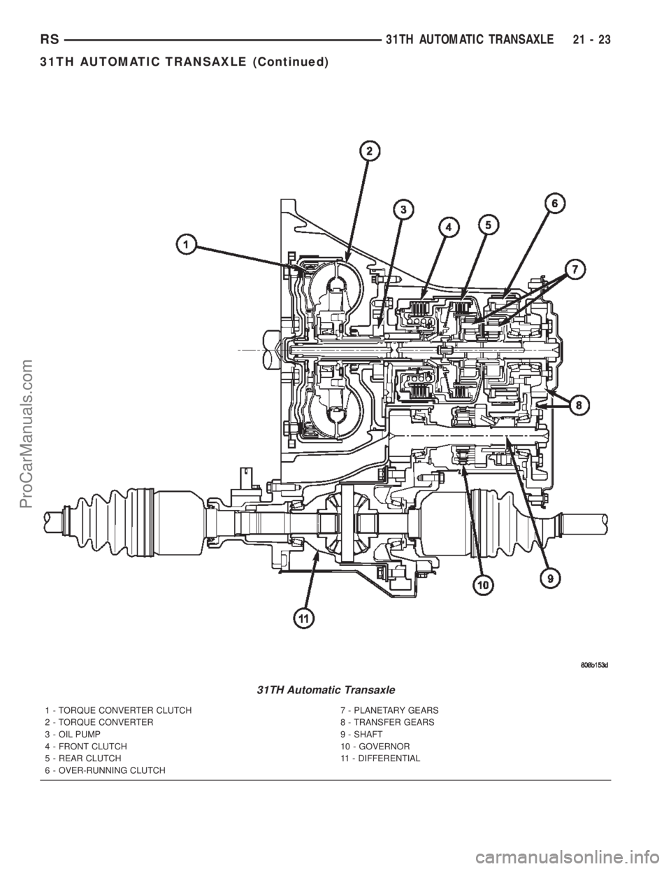
31TH Automatic Transaxle
1 - TORQUE CONVERTER CLUTCH
2 - TORQUE CONVERTER
3 - OIL PUMP
4 - FRONT CLUTCH
5 - REAR CLUTCH
6 - OVER-RUNNING CLUTCH7 - PLANETARY GEARS
8 - TRANSFER GEARS
9 - SHAFT
10 - GOVERNOR
11 - DIFFERENTIAL
RS31TH AUTOMATIC TRANSAXLE21-23
31TH AUTOMATIC TRANSAXLE (Continued)
ProCarManuals.com
Page 1583 of 2399
CONDITION POSSIBLE CAUSES CORRECTION
NO DRIVE RANGE
(REVERSE OK)1. Fluid Level Low. 1. Add fluid and check for leaks if drive is
restored.
2. Gearshift Linkage/Cable
Loose/Misadjusted.2. Repair or replace linkage components.
3. Rear Clutch Burnt. 3. Remove and disassemble transmission
and rear clutch and seals. Repair/replace
worn or damaged parts as needed.
4. Valve Body Malfunction. 4. Remove and disassemble valve body.
Replace assembly if any valves or bores
are damaged.
5. Transmission Overrunning Clutch
Broken.5. Remove and disassemble transmission.
Replace overrunning clutch.
6. Input Shaft Seal Rings Worn/
Damaged.6. Remove and disassemble transmission.
Replace seal rings and any other worn or
damaged parts.
7. Front Planetary Failed Broken. 7. Remove and repair.
NO DRIVE OR REVERSE
(VEHICLE WILL NOT
MOVE)1. Fluid Level Low. 1. Add fluid and check for leaks if drive is
restored.
2. Gearshift Linkage/Cable
Loose/Misadjusted.2. Inspect, adjust and reassemble linkage
as needed. Replace worn/damaged parts.
3. Filter Plugged. 3. Remove and disassemble transmission.
Repair or replace failed components as
needed. Replace filter. If filter and fluid
contained clutch material or metal particles,
an overhaul may be necessary. Perform
lube flow test. Flush oil. Replace cooler as
necessary.
4. Oil Pump Damaged. 4. Perform pressure test to confirm low
pressure. Replace pump body assembly if
necessary.
5. Valve Body Malfunctioned. 5. Check press and inspect valve body.
Replace valve body (as assembly) if any
valve or bore is damaged. Clean and
reassemble correctly if all parts are in good
condition.
6. Transmission Internal Component
Damaged.6. Remove and disassemble transmission.
Repair or replace failed components as
needed. Remove and disassemble
transmission. Repair or replace failed
components as needed.
7. Park Sprag not Releasing - Check
Stall Speed, Worn/Damaged/Stuck.7. Remove, disassemble, repair.
8. Torque Converter Damage. 8. Inspect and replace as required.
21 - 26 31TH AUTOMATIC TRANSAXLERS
31TH AUTOMATIC TRANSAXLE (Continued)
ProCarManuals.com
Page 1587 of 2399
CONDITION POSSIBLE CAUSES CORRECTION
GROWLING, GRATING OR
SCRAPING NOISES1. Drive Plate Broken. 1. Replace.
2. Torque Converter Bolts Hitting
Dust Shield.2. Dust shield bent. Replace or repair.
3. Planetary Gear Set Broken/
Seized.3. Check for debris in oil pan and repair as
required.
4. Overrunning Clutch Worn/Broken. 4. Inspect and check for debris in oil pan.
Repair as required.
5. Oil Pump Components Scored/
Binding.5. Remove, inspect and repair as required.
6. Output Shaft Bearing or Bushing
Damaged.6. Remove, inspect and repair as required.
7. Clutch Operation Faulty. 7. Perform air pressure check and repair as
required.
8. Front and Rear Bands
Misadjusted.8. Adjust bands.
DRAGS OR LOCKS UP 1. Fluid Level Low. 1. Check and adjust level.
2. Clutch Dragging/Failed 2. Air pressure check clutch operation and
repair as required.
3. Front or Rear Band Misadjusted. 3. Adjust bands.
4. Case Leaks Internally. 4. Check for leakage between passages in
case.
5. Servo Band or Linkage
Malfunction.5. Air pressure check servo operation and
repair as required.
6. Overrunning Clutch Worn. 6. Remove and inspect clutch. Repair as
required.
7. Planetary Gears Broken. 7. Remove, inspect and repair as required
(look for debris in oil pan).
WHINE/NOISE RELATED
TO ENGINE SPEED1. Fluid Level Low. 1. Add fluid and check for leaks.
2. Shift Cable Incorrect Routing. 2. Check shift cable for correct routing.
Should not touch engine or bell housing.
TORQUE CONVERTER
LOCKS UP IN SECOND
AND/OR THIRD GEARLockup Solenoid, Relay or Wiring
Shorted/Open.Test solenoid, relay and wiring for
continuity, shorts or grounds. Replace
solenoid and relay if faulty. Repair wiring
and connectors as necessary.
HARSH 1-2 OR 2-3
SHIFTSLockup Solenoid Malfunction. Remove valve body and replace solenoid
assembly.
NO START IN PARK OR
NEUTRAL1. Gearshift Linkage/Cable
Misadjusted.1. Adjust linkage/cable.
2. Neutral Switch Wire Open/Cut. 2. Check continuity with test lamp. Repair
as required.
3. Neutral Switch Faulty. 3. Refer to service section for test and
replacement procedure.
4. Neutral Switch Connect Faulty. 4. Connectors spread open. Repair.
5. Valve Body Manual Lever
Assembly Bent/Worn/Broken.5. Inspect lever assembly and replace if
damaged.
21 - 30 31TH AUTOMATIC TRANSAXLERS
31TH AUTOMATIC TRANSAXLE (Continued)
ProCarManuals.com
Page 1588 of 2399
CONDITION POSSIBLE CAUSES CORRECTION
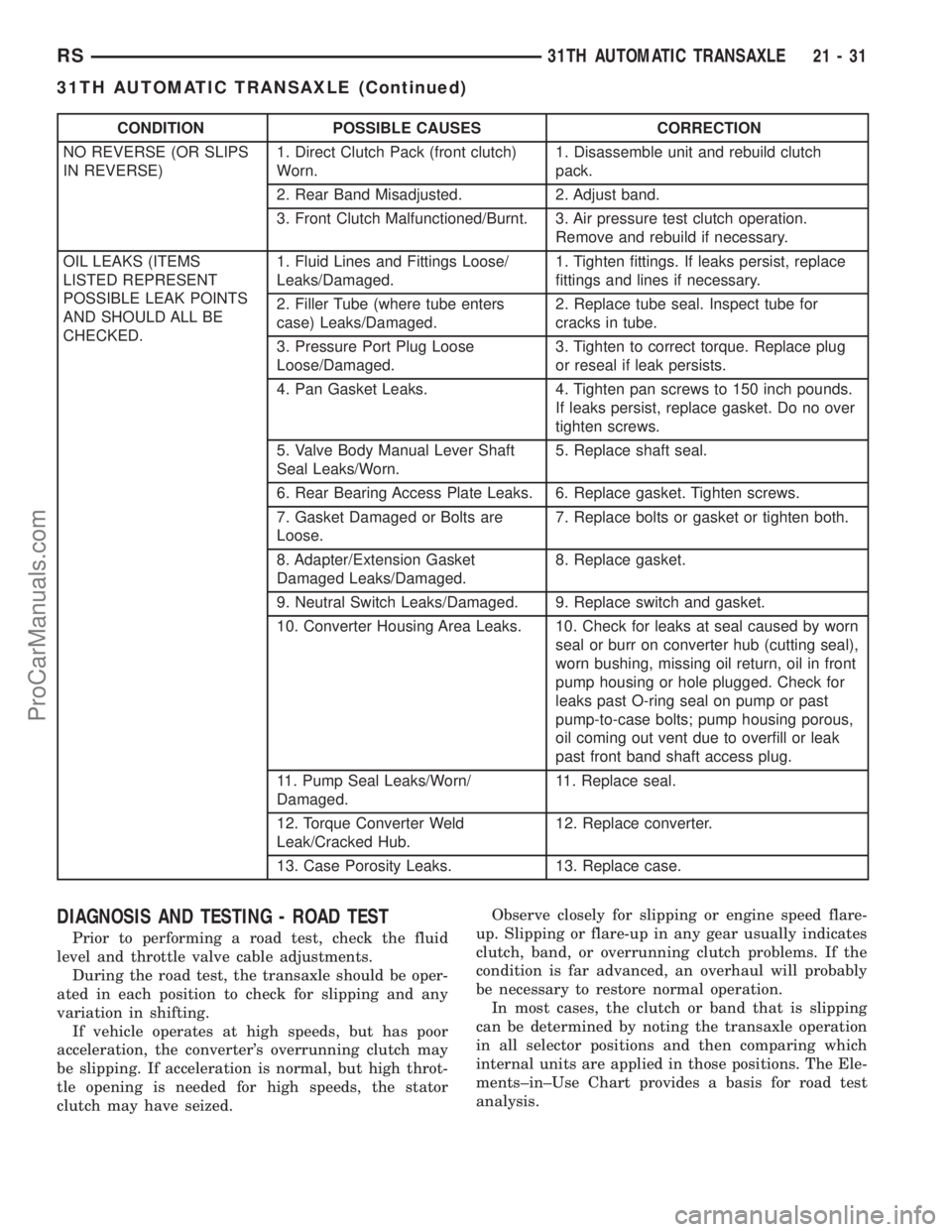
NO REVERSE (OR SLIPS
IN REVERSE)1. Direct Clutch Pack (front clutch)
Worn.1. Disassemble unit and rebuild clutch
pack.
2. Rear Band Misadjusted. 2. Adjust band.
3. Front Clutch Malfunctioned/Burnt. 3. Air pressure test clutch operation.
Remove and rebuild if necessary.
OIL LEAKS (ITEMS
LISTED REPRESENT
POSSIBLE LEAK POINTS
AND SHOULD ALL BE
CHECKED.1. Fluid Lines and Fittings Loose/
Leaks/Damaged.1. Tighten fittings. If leaks persist, replace
fittings and lines if necessary.
2. Filler Tube (where tube enters
case) Leaks/Damaged.2. Replace tube seal. Inspect tube for
cracks in tube.
3. Pressure Port Plug Loose
Loose/Damaged.3. Tighten to correct torque. Replace plug
or reseal if leak persists.
4. Pan Gasket Leaks. 4. Tighten pan screws to 150 inch pounds.
If leaks persist, replace gasket. Do no over
tighten screws.
5. Valve Body Manual Lever Shaft
Seal Leaks/Worn.5. Replace shaft seal.
6. Rear Bearing Access Plate Leaks. 6. Replace gasket. Tighten screws.
7. Gasket Damaged or Bolts are
Loose.7. Replace bolts or gasket or tighten both.
8. Adapter/Extension Gasket
Damaged Leaks/Damaged.8. Replace gasket.
9. Neutral Switch Leaks/Damaged. 9. Replace switch and gasket.
10. Converter Housing Area Leaks. 10. Check for leaks at seal caused by worn
seal or burr on converter hub (cutting seal),
worn bushing, missing oil return, oil in front
pump housing or hole plugged. Check for
leaks past O-ring seal on pump or past
pump-to-case bolts; pump housing porous,
oil coming out vent due to overfill or leak
past front band shaft access plug.
11. Pump Seal Leaks/Worn/
Damaged.11. Replace seal.
12. Torque Converter Weld
Leak/Cracked Hub.12. Replace converter.
13. Case Porosity Leaks. 13. Replace case.
DIAGNOSIS AND TESTING - ROAD TEST
Prior to performing a road test, check the fluid
level and throttle valve cable adjustments.
During the road test, the transaxle should be oper-
ated in each position to check for slipping and any
variation in shifting.
If vehicle operates at high speeds, but has poor
acceleration, the converter's overrunning clutch may
be slipping. If acceleration is normal, but high throt-
tle opening is needed for high speeds, the stator
clutch may have seized.Observe closely for slipping or engine speed flare-
up. Slipping or flare-up in any gear usually indicates
clutch, band, or overrunning clutch problems. If the
condition is far advanced, an overhaul will probably
be necessary to restore normal operation.
In most cases, the clutch or band that is slipping
can be determined by noting the transaxle operation
in all selector positions and then comparing which
internal units are applied in those positions. The Ele-
ments±in±Use Chart provides a basis for road test
analysis.
RS31TH AUTOMATIC TRANSAXLE21-31
31TH AUTOMATIC TRANSAXLE (Continued)
ProCarManuals.com
Page 1592 of 2399
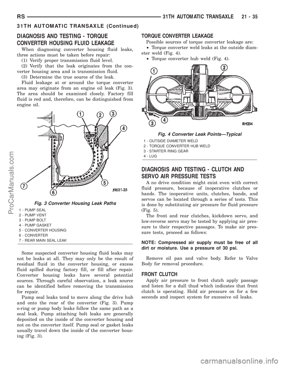
DIAGNOSIS AND TESTING - TORQUE
CONVERTER HOUSING FLUID LEAKAGE
When diagnosing converter housing fluid leaks,
three actions must be taken before repair:
(1) Verify proper transmission fluid level.
(2) Verify that the leak originates from the con-
verter housing area and is transmission fluid.
(3) Determine the true source of the leak.
Fluid leakage at or around the torque converter
area may originate from an engine oil leak (Fig. 3).
The area should be examined closely. Factory fill
fluid is red and, therefore, can be distinguished from
engine oil.
Some suspected converter housing fluid leaks may
not be leaks at all. They may only be the result of
residual fluid in the converter housing, or excess
fluid spilled during factory fill, or fill after repair.
Converter housing leaks have several potential
sources. Through careful observation, a leak source
can be identified before removing the transmission
for repair.
Pump seal leaks tend to move along the drive hub
and onto the rear of the converter (Fig. 3). Pump
o-ring or pump body leaks follow the same path as a
seal leak. Pump attaching bolt leaks are generally
deposited on the inside of the converter housing and
not on the converter itself. Pump seal or gasket leaks
usually travel down the inside of the converter hous-
ing (Fig. 3).
TORQUE CONVERTER LEAKAGE
Possible sources of torque converter leakage are:
²Torque converter weld leaks at the outside diam-
eter weld (Fig. 4).
²Torque converter hub weld (Fig. 4).
DIAGNOSIS AND TESTING - CLUTCH AND
SERVO AIR PRESSURE TESTS
A no drive condition might exist even with correct
fluid pressure, because of inoperative clutches or
bands. The inoperative units, clutches, bands, and
servos can be located through a series of tests. This
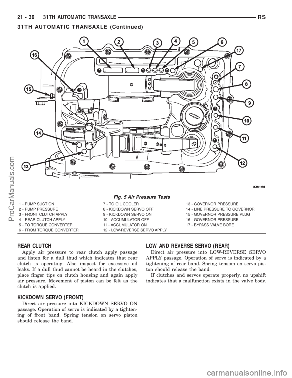
is done by substituting air pressure for fluid pressure
(Fig. 5).
The front and rear clutches, kickdown servo, and
low-reverse servo may be tested by applying air pres-
sure to their respective passages. To make air pres-
sure tests, proceed as follows:
NOTE: Compressed air supply must be free of all
dirt or moisture. Use a pressure of 30 psi.
Remove oil pan and valve body. Refer to Valve
Body for removal procedure.
FRONT CLUTCH
Apply air pressure to front clutch apply passage
and listen for a dull thud which indicates that front
clutch is operating. Hold air pressure on for a few
seconds and inspect system for excessive oil leaks.
Fig. 3 Converter Housing Leak Paths
1 - PUMP SEAL
2 - PUMP VENT
3 - PUMP BOLT
4 - PUMP GASKET
5 - CONVERTER HOUSING
6 - CONVERTER
7 - REAR MAIN SEAL LEAK
Fig. 4 Converter Leak PointsÐTypical
1 - OUTSIDE DIAMETER WELD
2 - TORQUE CONVERTER HUB WELD
3 - STARTER RING GEAR
4 - LUG
RS31TH AUTOMATIC TRANSAXLE21-35
31TH AUTOMATIC TRANSAXLE (Continued)
ProCarManuals.com
Page 1593 of 2399
REAR CLUTCH
Apply air pressure to rear clutch apply passage
and listen for a dull thud which indicates that rear
clutch is operating. Also inspect for excessive oil
leaks. If a dull thud cannot be heard in the clutches,
place finger tips on clutch housing and again apply
air pressure. Movement of piston can be felt as the
clutch is applied.
KICKDOWN SERVO (FRONT)
Direct air pressure into KICKDOWN SERVO ON
passage. Operation of servo is indicated by a tighten-
ing of front band. Spring tension on servo piston
should release the band.
LOW AND REVERSE SERVO (REAR)
Direct air pressure into LOW-REVERSE SERVO
APPLY passage. Operation of servo is indicated by a
tightening of rear band. Spring tension on servo pis-
ton should release the band.
If clutches and servos operate properly, no upshift
indicates that a malfunction exists in the valve body.
Fig. 5 Air Pressure Tests
1 - PUMP SUCTION 7 - TO OIL COOLER 13 - GOVERNOR PRESSURE
2 - PUMP PRESSURE 8 - KICKDOWN SERVO OFF 14 - LINE PRESSURE TO GOVERNOR
3 - FRONT CLUTCH APPLY 9 - KICKDOWN SERVO ON 15 - GOVERNOR PRESSURE PLUG
4 - REAR CLUTCH APPLY 10 - ACCUMULATOR OFF 16 - GOVERNOR PRESSURE
5 - TO TORQUE CONVERTER 11 - ACCUMULATOR ON 17 - BYPASS VALVE BORE
6 - FROM TORQUE CONVERTER 12 - LOW-REVERSE SERVO APPLY
21 - 36 31TH AUTOMATIC TRANSAXLERS
31TH AUTOMATIC TRANSAXLE (Continued)
ProCarManuals.com
Page 1594 of 2399
STANDARD PROCEDURE - ALUMINUM
THREAD REPAIR
Damaged or worn threads in the aluminum trans-
axle case and valve body can be repaired by the use
of Heli-Coils, or equivalent. This repair consists of
drilling out the worn-out damaged threads. Then tap-
ping the hole with a Heli-Coil tap, or equivalent, and
installing a Heli-Coil insert, or equivalent, into the
hole. This brings the hole back to its original thread
size.
Heli-Coil, or equivalent, tools and inserts are
readily available from most automotive parts suppli-
ers.
REMOVAL
(1) Disconnect battery negative cable.
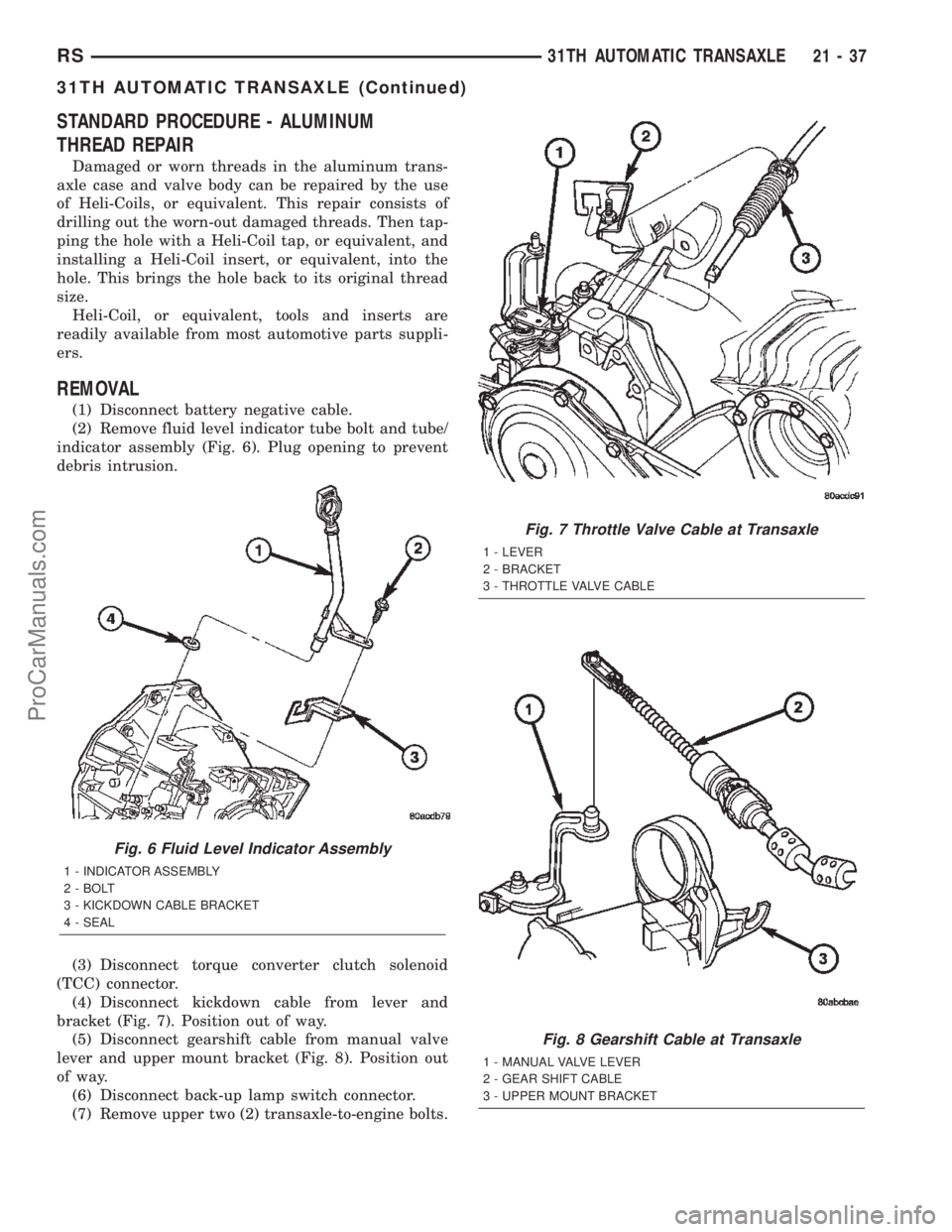
(2) Remove fluid level indicator tube bolt and tube/
indicator assembly (Fig. 6). Plug opening to prevent
debris intrusion.
(3) Disconnect torque converter clutch solenoid
(TCC) connector.
(4) Disconnect kickdown cable from lever and
bracket (Fig. 7). Position out of way.
(5) Disconnect gearshift cable from manual valve
lever and upper mount bracket (Fig. 8). Position out
of way.
(6) Disconnect back-up lamp switch connector.
(7) Remove upper two (2) transaxle-to-engine bolts.
Fig. 6 Fluid Level Indicator Assembly
1 - INDICATOR ASSEMBLY
2 - BOLT
3 - KICKDOWN CABLE BRACKET
4 - SEAL
Fig. 7 Throttle Valve Cable at Transaxle
1 - LEVER
2 - BRACKET
3 - THROTTLE VALVE CABLE
Fig. 8 Gearshift Cable at Transaxle
1 - MANUAL VALVE LEVER
2 - GEAR SHIFT CABLE
3 - UPPER MOUNT BRACKET
RS31TH AUTOMATIC TRANSAXLE21-37
31TH AUTOMATIC TRANSAXLE (Continued)
ProCarManuals.com
Page 1596 of 2399
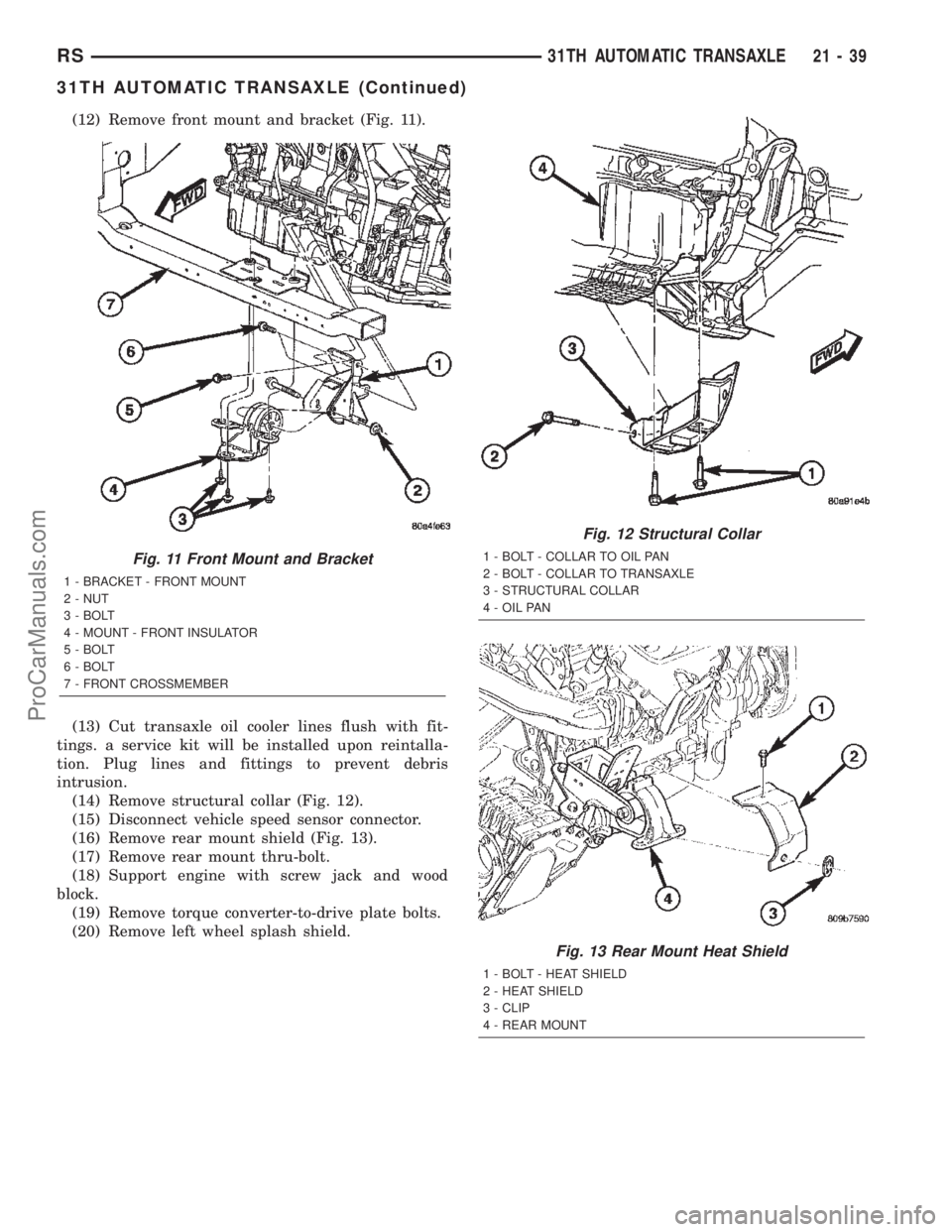
(12) Remove front mount and bracket (Fig. 11).
(13) Cut transaxle oil cooler lines flush with fit-
tings. a service kit will be installed upon reintalla-
tion. Plug lines and fittings to prevent debris
intrusion.
(14) Remove structural collar (Fig. 12).
(15) Disconnect vehicle speed sensor connector.
(16) Remove rear mount shield (Fig. 13).
(17) Remove rear mount thru-bolt.
(18) Support engine with screw jack and wood
block.
(19) Remove torque converter-to-drive plate bolts.
(20) Remove left wheel splash shield.
Fig. 11 Front Mount and Bracket
1 - BRACKET - FRONT MOUNT
2 - NUT
3 - BOLT
4 - MOUNT - FRONT INSULATOR
5 - BOLT
6 - BOLT
7 - FRONT CROSSMEMBER
Fig. 12 Structural Collar
1 - BOLT - COLLAR TO OIL PAN
2 - BOLT - COLLAR TO TRANSAXLE
3 - STRUCTURAL COLLAR
4 - OIL PAN
Fig. 13 Rear Mount Heat Shield
1 - BOLT - HEAT SHIELD
2 - HEAT SHIELD
3 - CLIP
4 - REAR MOUNT
RS31TH AUTOMATIC TRANSAXLE21-39
31TH AUTOMATIC TRANSAXLE (Continued)
ProCarManuals.com
Page 1612 of 2399
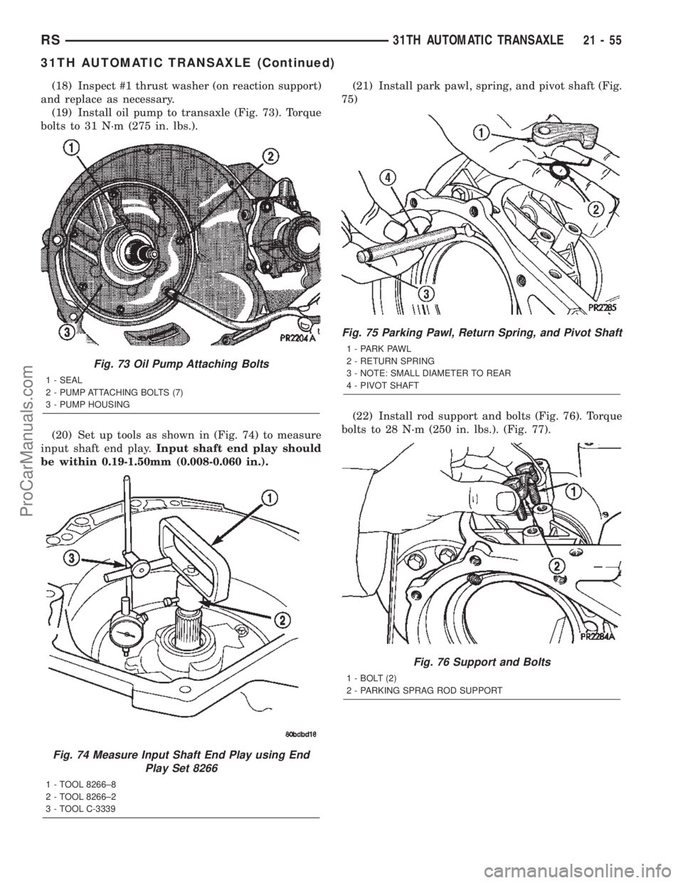
(18) Inspect #1 thrust washer (on reaction support)
and replace as necessary.
(19) Install oil pump to transaxle (Fig. 73). Torque
bolts to 31 N´m (275 in. lbs.).
(20) Set up tools as shown in (Fig. 74) to measure
input shaft end play.Input shaft end play should
be within 0.19-1.50mm (0.008-0.060 in.).(21) Install park pawl, spring, and pivot shaft (Fig.
75)
(22) Install rod support and bolts (Fig. 76). Torque
bolts to 28 N´m (250 in. lbs.). (Fig. 77).
Fig. 73 Oil Pump Attaching Bolts
1 - SEAL
2 - PUMP ATTACHING BOLTS (7)
3 - PUMP HOUSING
Fig. 74 Measure Input Shaft End Play using End
Play Set 8266
1 - TOOL 8266±8
2 - TOOL 8266±2
3 - TOOL C-3339
Fig. 75 Parking Pawl, Return Spring, and Pivot Shaft
1 - PARK PAWL
2 - RETURN SPRING
3 - NOTE: SMALL DIAMETER TO REAR
4 - PIVOT SHAFT
Fig. 76 Support and Bolts
1 - BOLT (2)
2 - PARKING SPRAG ROD SUPPORT
RS31TH AUTOMATIC TRANSAXLE21-55
31TH AUTOMATIC TRANSAXLE (Continued)
ProCarManuals.com