engine CHRYSLER VOYAGER 2002 Service Manual
[x] Cancel search | Manufacturer: CHRYSLER, Model Year: 2002, Model line: VOYAGER, Model: CHRYSLER VOYAGER 2002Pages: 2399, PDF Size: 57.96 MB
Page 1265 of 2399

(3) Install crankshaft vibration damper. (Refer to 9
- ENGINE/ENGINE BLOCK/VIBRATION DAMPER -
INSTALLATION)
TIMING BELT AND
SPROCKET(S)
REMOVAL
REMOVAL - TIMING BELT
(1) Remove air cleaner upper cover, housing, and
clean air tube.
(2) Remove make-up air hose from cylinder head
cover.
(3) Raise vehicle on hoist.
(4) Remove right front wheel.
(5) Remove right inner splash shield.
(6) Remove accessory drive belts. (Refer to 7 -
COOLING/ACCESSORY DRIVE/BELT TENSION-
ERS - REMOVAL)
Fig. 113 ENGINE FRONT MOUNT BRACKET
1 - ENGINE MOUNT BRACKET
2 - BOLTS - 61 N´m (45 ft. lbs.)
Fig. 114 Camshaft Sprocket - Removal/Installation
1 - SPECIAL TOOL 6847
Fig. 115 Timing Belt Rear Cover
1 - BOLTS - REAR COVER 12 N´m (105 in. lbs.)
2 - BOLTS - REAR COVER 28 N´m (250 in. lbs.)
3 - TIMING BELT TENSIONER
9 - 64 ENGINE 2.4LRS
TIMING BELT COVER(S) (Continued)
ProCarManuals.com
Page 1266 of 2399
(7) Remove crankshaft vibration damper. (Refer to
9 - ENGINE/ENGINE BLOCK/VIBRATION
DAMPER - REMOVAL)
(8) Remove air conditioner/generator belt tensioner
and pulley assembly. (Refer to 7 - COOLING/ACCES-
SORY DRIVE/BELT TENSIONERS - REMOVAL)
(9) Remove timing belt lower front cover bolts and
remove cover. (Refer to 9 - ENGINE/VALVE TIMING/
TIMING BELT / CHAIN COVER(S) - REMOVAL)
(10) Lower vehicle.
(11) Remove bolts attaching timing belt upper
front cover and remove cover. (Refer to 9 - ENGINE/
VALVE TIMING/TIMING BELT / CHAIN COVER(S)
- REMOVAL)
(12) Remove right engine mount. (Refer to 9 -
ENGINE/ENGINE MOUNTING/RIGHT MOUNT -
REMOVAL)
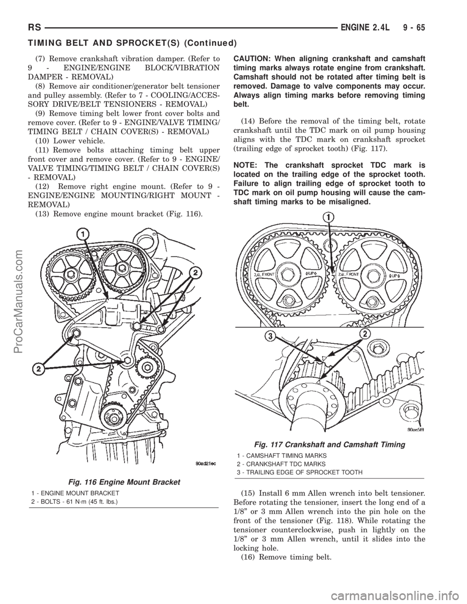
(13) Remove engine mount bracket (Fig. 116).CAUTION: When aligning crankshaft and camshaft
timing marks always rotate engine from crankshaft.
Camshaft should not be rotated after timing belt is
removed. Damage to valve components may occur.
Always align timing marks before removing timing
belt.
(14) Before the removal of the timing belt, rotate
crankshaft until the TDC mark on oil pump housing
aligns with the TDC mark on crankshaft sprocket
(trailing edge of sprocket tooth) (Fig. 117).
NOTE: The crankshaft sprocket TDC mark is
located on the trailing edge of the sprocket tooth.
Failure to align trailing edge of sprocket tooth to
TDC mark on oil pump housing will cause the cam-
shaft timing marks to be misaligned.
(15) Install 6 mm Allen wrench into belt tensioner.
Before rotating the tensioner, insert the long end of a
1/8º or 3 mm Allen wrench into the pin hole on the
front of the tensioner (Fig. 118). While rotating the
tensioner counterclockwise, push in lightly on the
1/8º or 3 mm Allen wrench, until it slides into the
locking hole.
(16) Remove timing belt.
Fig. 116 Engine Mount Bracket
1 - ENGINE MOUNT BRACKET
2 - BOLTS - 61 N´m (45 ft. lbs.)
Fig. 117 Crankshaft and Camshaft Timing
1 - CAMSHAFT TIMING MARKS
2 - CRANKSHAFT TDC MARKS
3 - TRAILING EDGE OF SPROCKET TOOTH
RSENGINE 2.4L9-65
TIMING BELT AND SPROCKET(S) (Continued)
ProCarManuals.com
Page 1267 of 2399
REMOVAL - CRANKSHAFT SPROCKET
(1) Disconnect negative battery cable.
(2) Remove timing belt (Refer to 9 - ENGINE/
VALVE TIMING/TIMING BELT/CHAIN AND
SPROCKETS - REMOVAL).
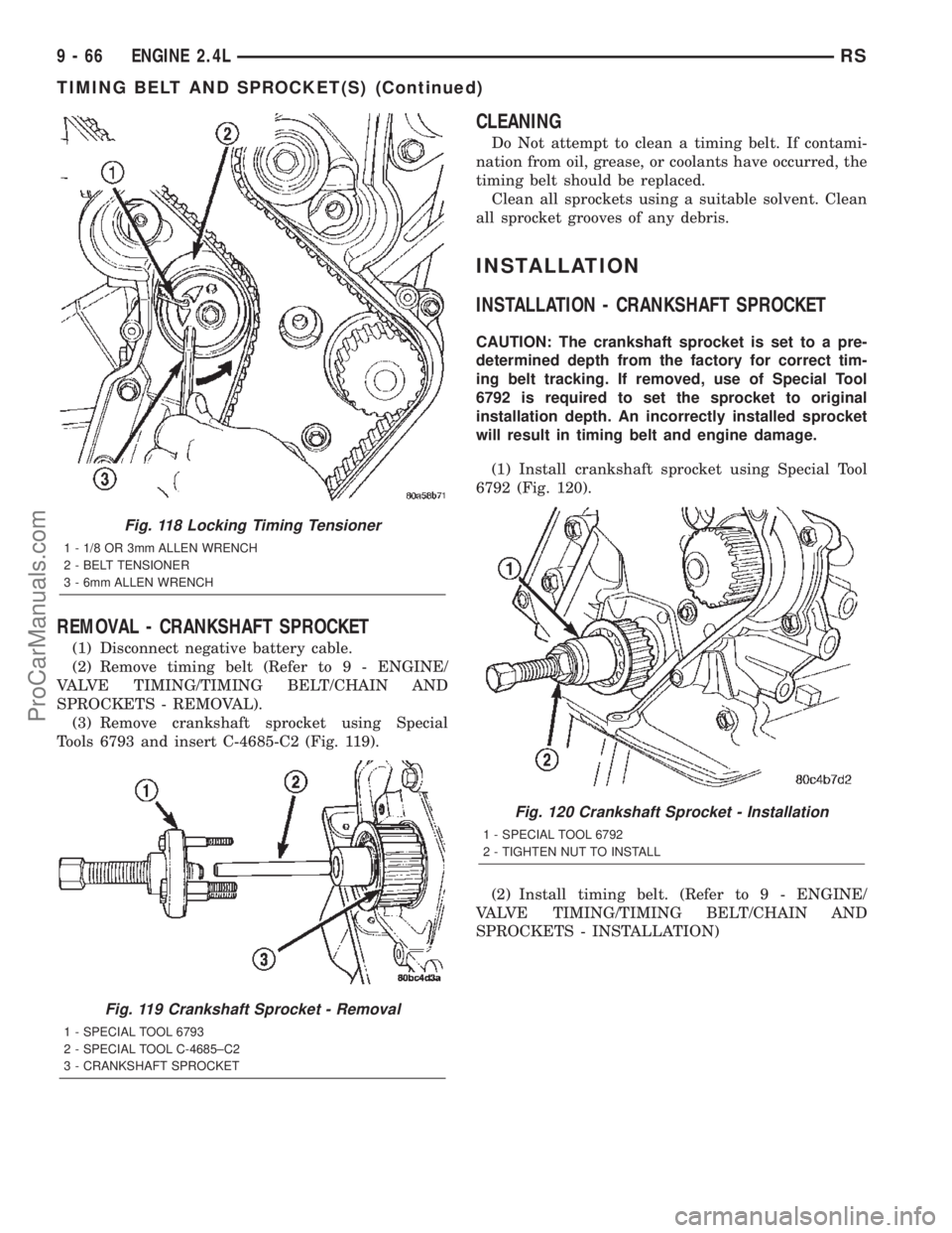
(3) Remove crankshaft sprocket using Special
Tools 6793 and insert C-4685-C2 (Fig. 119).
CLEANING
Do Not attempt to clean a timing belt. If contami-
nation from oil, grease, or coolants have occurred, the
timing belt should be replaced.
Clean all sprockets using a suitable solvent. Clean
all sprocket grooves of any debris.
INSTALLATION
INSTALLATION - CRANKSHAFT SPROCKET
CAUTION: The crankshaft sprocket is set to a pre-
determined depth from the factory for correct tim-
ing belt tracking. If removed, use of Special Tool
6792 is required to set the sprocket to original
installation depth. An incorrectly installed sprocket
will result in timing belt and engine damage.
(1) Install crankshaft sprocket using Special Tool
6792 (Fig. 120).
(2) Install timing belt. (Refer to 9 - ENGINE/
VALVE TIMING/TIMING BELT/CHAIN AND
SPROCKETS - INSTALLATION)
Fig. 118 Locking Timing Tensioner
1 - 1/8 OR 3mm ALLEN WRENCH
2 - BELT TENSIONER
3 - 6mm ALLEN WRENCH
Fig. 119 Crankshaft Sprocket - Removal
1 - SPECIAL TOOL 6793
2 - SPECIAL TOOL C-4685±C2
3 - CRANKSHAFT SPROCKET
Fig. 120 Crankshaft Sprocket - Installation
1 - SPECIAL TOOL 6792
2 - TIGHTEN NUT TO INSTALL
9 - 66 ENGINE 2.4LRS
TIMING BELT AND SPROCKET(S) (Continued)
ProCarManuals.com
Page 1268 of 2399
INSTALLATION - TIMING BELT
CAUTION: The crankshaft sprocket is set to a pre-
determined depth from the factory for correct tim-
ing belt tracking. If removed, use of Special Tool
6792 is required to set the sprocket to original
installation depth. An incorrectly installed sprocket
will result in timing belt and engine damage.
(1) Set crankshaft sprocket to TDC by aligning the
sprocket with the arrow on the oil pump housing.
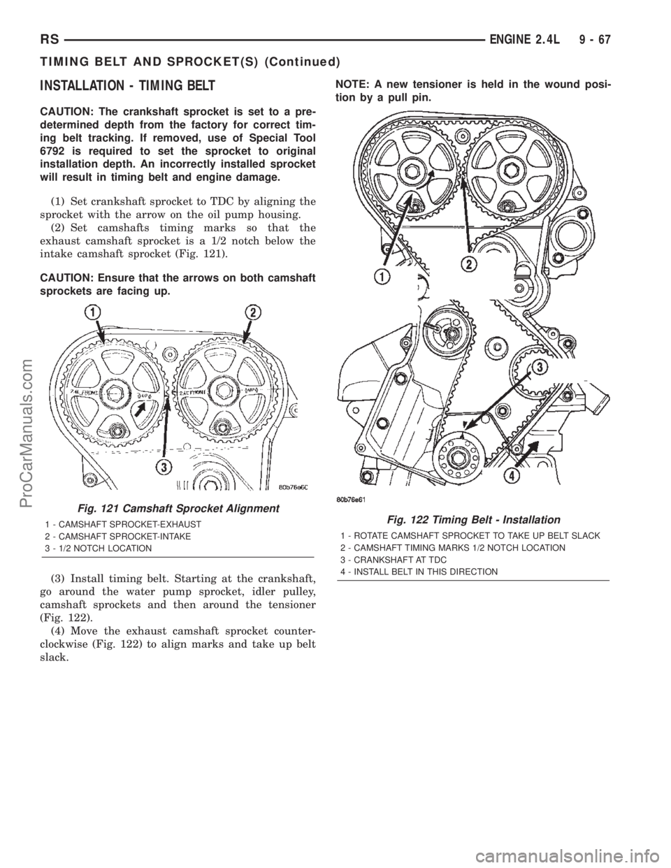
(2) Set camshafts timing marks so that the
exhaust camshaft sprocket is a 1/2 notch below the
intake camshaft sprocket (Fig. 121).
CAUTION: Ensure that the arrows on both camshaft
sprockets are facing up.
(3) Install timing belt. Starting at the crankshaft,
go around the water pump sprocket, idler pulley,
camshaft sprockets and then around the tensioner
(Fig. 122).
(4) Move the exhaust camshaft sprocket counter-
clockwise (Fig. 122) to align marks and take up belt
slack.NOTE: A new tensioner is held in the wound posi-
tion by a pull pin.
Fig. 121 Camshaft Sprocket Alignment
1 - CAMSHAFT SPROCKET-EXHAUST
2 - CAMSHAFT SPROCKET-INTAKE
3 - 1/2 NOTCH LOCATIONFig. 122 Timing Belt - Installation
1 - ROTATE CAMSHAFT SPROCKET TO TAKE UP BELT SLACK
2 - CAMSHAFT TIMING MARKS 1/2 NOTCH LOCATION
3 - CRANKSHAFT AT TDC
4 - INSTALL BELT IN THIS DIRECTION
RSENGINE 2.4L9-67
TIMING BELT AND SPROCKET(S) (Continued)
ProCarManuals.com
Page 1269 of 2399

(5) Remove the pull pin or Allen wrench from the
belt tensioner.
(6) Once the timing belt has been installed and
tensioner released, rotate the crankshaft two (2) com-
plete revolutions. Verify that the TDC marks on
crankshaft and timing marks on the camshafts are
aligned as shown in (Fig. 123).
(7) Install engine mount bracket to engine (Fig.
116).
(8) Install timing belt front covers and bolts.
(Refer to 9 - ENGINE/VALVE TIMING/TIMING
BELT / CHAIN COVER(S) - INSTALLATION)
(9) Install air conditioning/generator belt tensioner
and pulley. (Refer to 7 - COOLING/ACCESSORY
DRIVE/BELT TENSIONERS - INSTALLATION)
(10) Install right engine mount. (Refer to 9 -
ENGINE/ENGINE MOUNTING/RIGHT MOUNT -
INSTALLATION)(11) Install crankshaft vibration damper. (Refer to
9 - ENGINE/ENGINE BLOCK/VIBRATION
DAMPER - INSTALLATION)
(12) Install accessory drive belts. (Refer to 7 -
COOLING/ACCESSORY DRIVE/DRIVE BELTS -
INSTALLATION)
(13) Install drive belt splash shield.
(14) Install right front wheel.
(15) Connect make-up air hose to cylinder head
cover.
(16) Install air cleaner housing, upper cover, and
clean air tube.
TIMING BELT TENSIONER &
PULLEY
REMOVAL
(1) Remove the timing belt (Refer to 9 - ENGINE/
VALVE TIMING/TIMING BELT AND SPROCKETS -
REMOVAL).
(2) Remove timing belt idler pulley.
(3) Hold camshaft sprocket with Special Tool 6847
while removing bolt (Fig. 124). Remove both cam
sprockets.
Fig. 123 Crankshaft and Camshaft Timing
1 - CAMSHAFT TIMING MARKS
2 - CRANKSHAFT TDC MARKS
3 - TRAILING EDGE OF SPROCKET TOOTH
Fig. 124 Camshaft Sprocket - Removal/Installation
1 - SPECIAL TOOL 6847
9 - 68 ENGINE 2.4LRS
TIMING BELT AND SPROCKET(S) (Continued)
ProCarManuals.com
Page 1270 of 2399

(4) Remove rear timing belt cover fasteners and
remove cover from engine (Fig. 125).
(5) Remove lower bolt attaching timing belt ten-
sioner assembly to engine and remove tensioneras
an assembly(Fig. 126).
INSTALLATION
(1) Align timing belt tensioner assembly to engine
and install lower mounting boltbut do not tighten
(Fig. 126). To properly align tensioner assemblyÐin-
stall one of the engine bracket mounting bolts (M10)
5 to 7 turns into the tensioner's upper mounting loca-
tion (Fig. 126).
(2) Torque the tensioner's lower mounting bolt to
61 N´m (45 ft. lbs.). Remove the upper bolt used for
tensioner alignment.(3) Install rear timing belt cover and fasteners
(Fig. 125).
(4) Install timing belt idler pulley and torque
mounting bolt to 61 N´m (45 ft. lbs.).
(5) Install camshaft sprockets. Use Special Tool
6847 to hold sprockets (Fig. 124), torque bolts to 101
N´m (75 ft. lbs.).
(6) Install the timing belt (Refer to 9 - ENGINE/
VALVE TIMING/TIMING BELT AND SPROCKETS -
INSTALLATION).BALANCE SHAFTS AND
CARRIER ASSEMBLY
DESCRIPTION
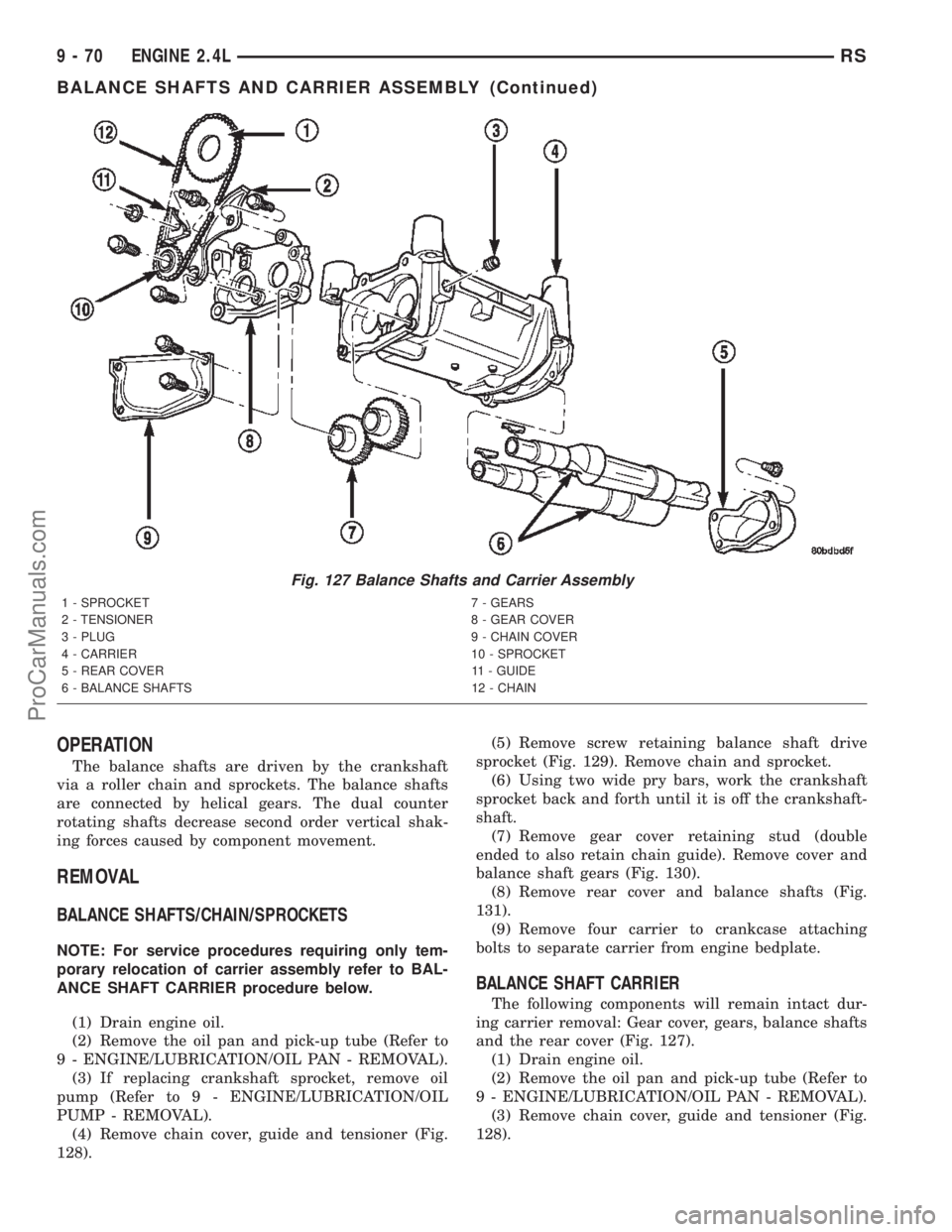
The 2.4L engine is equipped with two nodular cast
iron balance shafts installed in a cast aluminum car-
rier attached to the lower cylinder block (Fig. 127).
Fig. 125 Rear Timing Belt Cover Fasteners
1 - BOLTS - REAR COVER 12 N´m (105 in. lbs.)
2 - BOLTS - REAR COVER 28 N´m (250 in. lbs.)
3 - TIMING BELT TENSIONER
Fig. 126 Timing Belt Tensioner AssemblyÐRemoval/
Installation
1 - TIMING BELT TENSIONER ASSEMBLY
2 - TENSIONER ASSEMBLY UPPER BOLT
3 - TENSIONER ASSEMBLY LOWER BOLT
RSENGINE 2.4L9-69
TIMING BELT TENSIONER & PULLEY (Continued)
ProCarManuals.com
Page 1271 of 2399
OPERATION
The balance shafts are driven by the crankshaft
via a roller chain and sprockets. The balance shafts
are connected by helical gears. The dual counter
rotating shafts decrease second order vertical shak-
ing forces caused by component movement.
REMOVAL
BALANCE SHAFTS/CHAIN/SPROCKETS
NOTE: For service procedures requiring only tem-
porary relocation of carrier assembly refer to BAL-
ANCE SHAFT CARRIER procedure below.
(1) Drain engine oil.
(2) Remove the oil pan and pick-up tube (Refer to
9 - ENGINE/LUBRICATION/OIL PAN - REMOVAL).
(3) If replacing crankshaft sprocket, remove oil
pump (Refer to 9 - ENGINE/LUBRICATION/OIL
PUMP - REMOVAL).
(4) Remove chain cover, guide and tensioner (Fig.
128).(5) Remove screw retaining balance shaft drive
sprocket (Fig. 129). Remove chain and sprocket.
(6) Using two wide pry bars, work the crankshaft
sprocket back and forth until it is off the crankshaft-
shaft.
(7) Remove gear cover retaining stud (double
ended to also retain chain guide). Remove cover and
balance shaft gears (Fig. 130).
(8) Remove rear cover and balance shafts (Fig.
131).
(9) Remove four carrier to crankcase attaching
bolts to separate carrier from engine bedplate.
BALANCE SHAFT CARRIER
The following components will remain intact dur-
ing carrier removal: Gear cover, gears, balance shafts
and the rear cover (Fig. 127).
(1) Drain engine oil.
(2) Remove the oil pan and pick-up tube (Refer to
9 - ENGINE/LUBRICATION/OIL PAN - REMOVAL).
(3) Remove chain cover, guide and tensioner (Fig.
128).
Fig. 127 Balance Shafts and Carrier Assembly
1 - SPROCKET 7 - GEARS
2 - TENSIONER 8 - GEAR COVER
3 - PLUG 9 - CHAIN COVER
4 - CARRIER 10 - SPROCKET
5 - REAR COVER 11 - GUIDE
6 - BALANCE SHAFTS 12 - CHAIN
9 - 70 ENGINE 2.4LRS
BALANCE SHAFTS AND CARRIER ASSEMBLY (Continued)
ProCarManuals.com
Page 1272 of 2399

(4) Remove screw retaining balance shaft drive
sprocket (Fig. 129).
(5) Move balance shaft inboard through drive
chain sprocket. Sprocket will hang in lower chain
loop.
(6) Remove carrier to crankcase attaching bolts to
remove carrier.
INSTALLATION
BALANCE SHAFT INSTALLATION/TIMING
Balance shaft and carrier assembly installation is
the reverse of the removal procedure.During instal-
lation crankshaft-to-balance shaft timing must
be established. Refer to Timing procedure in
this section.
(1) With balance shafts installed in carrier (Fig.
127) position carrier on crankcase and install four
attaching bolts and tighten to 54 N´m (40 ft. lbs.).
(2) Turn balance shafts until both shaft key ways
are up, parallel to vertical centerline of engine.
Install short hub drive gear on sprocket driven shaft
and long hub gear on gear driven shaft. After instal-
lation gear and balance shaft keyways must be upwith gear timing marks meshed as shown in (Fig.
132).
(3) Install gear cover and tighten double ended
stud/washer fastener to 12 N´m (105 in. lbs.).
Fig. 128 Chain Cover, Guide and Tensioner
1 - STUD
2 - TENSIONER (ADJUSTER)
3 - GEAR COVER
4 - ADJUST SCREW
5 - PIVOT SCREW
6 - CHAIN COVER (CUTAWAY)
7 - GUIDE
Fig. 129 Drive Chain and Sprockets
1 - NICKEL PLATED LINK AND MARK
2 - GEAR/SPROCKET SCREWS
3 - NICKEL PLATED LINK AND DOT
Fig. 130 Gear Cover and Gears
1 - STUD (DOUBLE ENDED)
2 - DRIVE GEAR
3 - DRIVEN GEAR
4 - CARRIER DOWEL
5 - GEAR(S)
6 - GEAR COVER
RSENGINE 2.4L9-71
BALANCE SHAFTS AND CARRIER ASSEMBLY (Continued)
ProCarManuals.com
Page 1273 of 2399

(4) Align flat on balance shaft drive sprocket to the
flat on crankshaft (Fig. 133).
(5) Install balance shaft drive sprocket on crank-
shaft using Special Tool 6052 (Fig. 134).
(6) Turn crankshaft until number 1 cylinder is at
top dead center (TDC). The timing marks on the
chain sprocket should line up with the parting line
on the left side of number one main bearing cap.
(Fig. 135).
(7) Place chain over crankshaft sprocket so that
the plated link of the chain is over the number 1 cyl-inder timing mark on the balance shaft crankshaft
sprocket (Fig. 135).
(8) Place balance shaft sprocket into the timing
chain (Fig. 135) and align the timing mark on the
sprocket (dot) with the (lower) plated link on the
chain.
NOTE: The lower plated link is 8 links from the
upper link.
Fig. 131 Balance Shaft - Removal/Installation
1 - REAR COVER
2 - CARRIER
3 - BALANCE SHAFT
Fig. 132 Gear Timing
1 - KEY WAYS UP
2 - GEAR ALIGNMENT DOTS
Fig. 133 Balance Shaft Sprocket Alignment to
Crankshaft
1 - ALIGN FLATS
Fig. 134 Balance Shaft Drive
1 - SPROCKET
2 - SPECIAL TOOL 6052
9 - 72 ENGINE 2.4LRS
BALANCE SHAFTS AND CARRIER ASSEMBLY (Continued)
ProCarManuals.com
Page 1274 of 2399
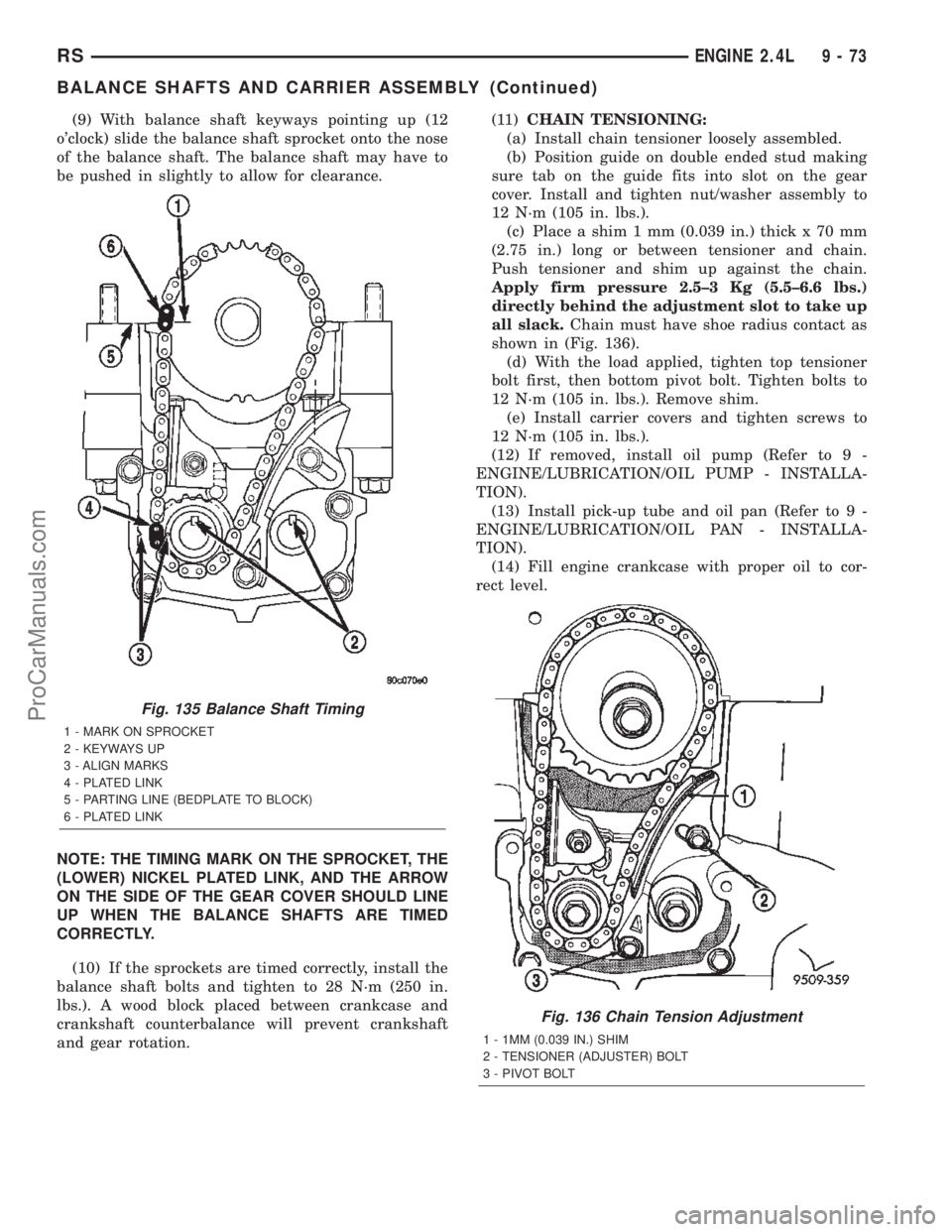
(9) With balance shaft keyways pointing up (12
o'clock) slide the balance shaft sprocket onto the nose
of the balance shaft. The balance shaft may have to
be pushed in slightly to allow for clearance.
NOTE: THE TIMING MARK ON THE SPROCKET, THE
(LOWER) NICKEL PLATED LINK, AND THE ARROW
ON THE SIDE OF THE GEAR COVER SHOULD LINE
UP WHEN THE BALANCE SHAFTS ARE TIMED
CORRECTLY.
(10) If the sprockets are timed correctly, install the
balance shaft bolts and tighten to 28 N´m (250 in.
lbs.). A wood block placed between crankcase and
crankshaft counterbalance will prevent crankshaft
and gear rotation.(11)CHAIN TENSIONING:
(a) Install chain tensioner loosely assembled.
(b) Position guide on double ended stud making
sure tab on the guide fits into slot on the gear
cover. Install and tighten nut/washer assembly to
12 N´m (105 in. lbs.).
(c) Place a shim 1 mm (0.039 in.) thick x 70 mm
(2.75 in.) long or between tensioner and chain.
Push tensioner and shim up against the chain.
Apply firm pressure 2.5±3 Kg (5.5±6.6 lbs.)
directly behind the adjustment slot to take up
all slack.Chain must have shoe radius contact as
shown in (Fig. 136).
(d) With the load applied, tighten top tensioner
bolt first, then bottom pivot bolt. Tighten bolts to
12 N´m (105 in. lbs.). Remove shim.
(e) Install carrier covers and tighten screws to
12 N´m (105 in. lbs.).
(12) If removed, install oil pump (Refer to 9 -
ENGINE/LUBRICATION/OIL PUMP - INSTALLA-
TION).
(13) Install pick-up tube and oil pan (Refer to 9 -
ENGINE/LUBRICATION/OIL PAN - INSTALLA-
TION).
(14) Fill engine crankcase with proper oil to cor-
rect level.
Fig. 135 Balance Shaft Timing
1 - MARK ON SPROCKET
2 - KEYWAYS UP
3 - ALIGN MARKS
4 - PLATED LINK
5 - PARTING LINE (BEDPLATE TO BLOCK)
6 - PLATED LINK
Fig. 136 Chain Tension Adjustment
1 - 1MM (0.039 IN.) SHIM
2 - TENSIONER (ADJUSTER) BOLT
3 - PIVOT BOLT
RSENGINE 2.4L9-73
BALANCE SHAFTS AND CARRIER ASSEMBLY (Continued)
ProCarManuals.com