mirror CHRYSLER VOYAGER 2002 Service Manual
[x] Cancel search | Manufacturer: CHRYSLER, Model Year: 2002, Model line: VOYAGER, Model: CHRYSLER VOYAGER 2002Pages: 2399, PDF Size: 57.96 MB
Page 338 of 2399

ELECTRONIC CONTROL MODULES
TABLE OF CONTENTS
page page
ELECTRONIC CONTROL MODULES
STANDARD PROCEDURE - PCM/SKIM
PROGRAMMING.......................2
ADJUSTABLE PEDAL MODULE
DIAGNOSIS AND TESTING - ADJUSTABLE
PEDAL MODULE.......................3
REMOVAL.............................3
INSTALLATION..........................3
BODY CONTROL MODULE
DESCRIPTION..........................3
OPERATION............................3
REMOVAL.............................5
INSTALLATION..........................5
CONTROLLER ANTILOCK BRAKE
DESCRIPTION..........................5
OPERATION............................5
REMOVAL.............................6
INSTALLATION..........................6
DATA LINK CONNECTOR
DESCRIPTION..........................7
OPERATION............................7
FRONT CONTROL MODULE
DESCRIPTION..........................7
OPERATION............................7
DIAGNOSIS AND TESTING - FRONT
CONTROL MODULE....................8
REMOVAL.............................8
INSTALLATION..........................8
HEATED SEAT MODULE
DESCRIPTION..........................9
OPERATION............................9
DIAGNOSIS AND TESTING - HEATED SEAT
MODULE.............................9
REMOVAL.............................10
INSTALLATION.........................10
POWER LIFTGATE MODULE
DESCRIPTION.........................10
OPERATION...........................10
REMOVAL.............................10
INSTALLATION.........................11
POWERTRAIN CONTROL MODULE
DESCRIPTION
DESCRIPTION........................11DIAGNOSTIC TROUBLE CODE...........13
OPERATION - SENSOR RETURN - PCM
INPUT..............................25
OPERATION - SCI RECEIVE - PCM INPUT . . 25
OPERATION - IGNITION SENSE - PCM
INPUT..............................25
OPERATION - PCM GROUND............25
OPERATION
OPERATION - 8-VOLT SUPPLY - PCM
OUTPUT............................25
OPERATION - 5 VOLT SUPPLY - PCM
OUTPUT............................25
STANDARD PROCEDURE - OBTAINING
DIAGNOSTIC TROUBLE CODES..........25
REMOVAL.............................26
INSTALLATION.........................26
SENTRY KEY IMMOBILIZER MODULE
DESCRIPTION.........................26
OPERATION...........................27
REMOVAL.............................27
INSTALLATION.........................27
TRANSMISSION CONTROL MODULE
DESCRIPTION.........................28
OPERATION...........................28
STANDARD PROCEDURE
STANDARD PROCEDURE - PINION
FACTOR SETTING.....................31
STANDARD PROCEDURE - QUICK LEARN
PROCEDURE........................31
REMOVAL.............................31
INSTALLATION.........................32
MEMORY SEAT/MIRROR MODULE
DESCRIPTION.........................33
OPERATION...........................33
DIAGNOSIS AND TESTING - MEMORY
SEAT/MIRROR MODULE................33
REMOVAL.............................33
INSTALLATION.........................33
SLIDING DOOR CONTROL MODULE
DESCRIPTION.........................33
OPERATION...........................34
REMOVAL.............................34
INSTALLATION.........................34
RSELECTRONIC CONTROL MODULES8E-1
ProCarManuals.com
Page 341 of 2399

interior lamps after 15 minutes after the ignition is
turned off, if they are not turned off by the driver.
²Chime Driver
²Compass/Mini-Trip support.
²Interior Lighting (Courtesy/Reading Lamps)
²BCM Diagnostic Reporting
²Electronic Liftgate Release (with Power Door
Locks)
²Exterior Lighting
²Headlamp Time Delay (with/without Automatic
Headlamps)
²Illuminated Entry
²Fade to Off Interior Lamps - This feature dims
the interior lighting (courtesy lamps) gradually if theBCM does not receive any new inputs that would
cause the interior lamps to remain on.
²Pulse Width Modulated Instrument Panel Dim-
ming
²Door Lock Inhibit - This feature disables the
door lock functions if the key is in the ignition and
either front door is ajar. Pressing the Remote Keyless
Entry (RKE) lock/unlock button under these condi-
tions result in normal lock/unlock activation.
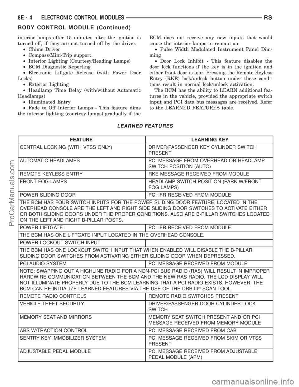
The BCM has the ability to LEARN additional fea-
tures in the vehicle, provided the appropriate switch
input and PCI data bus messages are received. Refer
to the LEARNED FEATURES table.
LEARNED FEATURES
FEATURE LEARNING KEY
CENTRAL LOCKING (WITH VTSS ONLY) DRIVER/PASSENGER KEY CYLINDER SWITCH
PRESENT
AUTOMATIC HEADLAMPS PCI MESSAGE FROM OVERHEAD OR HEADLAMP
SWITCH POSITION (AUTO)
REMOTE KEYLESS ENTRY RKE MESSAGE RECEIVED FROM MODULE
FRONT FOG LAMPS HEADLAMP SWITCH POSITION (PARK W/FRONT
FOG LAMPS)
POWER SLIDING DOOR PCI IFR RECEIVED FROM MODULE
THE BCM HAS FOUR SWITCH INPUTS FOR THE POWER SLIDING DOOR FEATURE; LOCATED IN THE
OVERHEAD CONSOLE ARE THE LEFT AND RIGHT SIDE SLIDING DOOR SWITCHES TO ACTIVATE EITHER
OR BOTH SLIDING DOORS UNDER THE PROPER CONDITIONS. ALSO ARE B-PILLAR SWITCHES LOCATED
ON THE LEFT AND RIGHT B-PILLAR POSTS.
POWER LIFTGATE PCI IFR RECEIVED FROM MODULE
THE BCM HAS ONE LIFTGATE INPUT LOCATED IN THE OVERHEAD CONSOLE.
POWER LOCKOUT SWITCH INPUT
THE BCM HAS ONE LOCKOUT SWITCH INPUT THAT WHEN ENABLED WILL DISABLE THE B-PILLAR
SLIDING DOOR SWITCHES FROM ACTIVATING EITHER SLIDING DOOR WHEN DEPRESSED.
PCI AUDIO SYSTEM PCI MESSAGE RECEIVED FROM MODULE
NOTE: SWAPPING OUT A HIGHLINE RADIO FOR A NON-PCI BUS RADIO (RAS) WILL RESULT IN IMPROPER
HARDWIRE COMMUNICATION BETWEEN THE BCM AND THE NEW RAS RADIO. THE LCD DISPLAY WILL
NOT ILLUMINATE PROPERLY DUE TO THE BCM LEARNING THAT A PCI RADIO EXISTS. HOWEVER, THE
BCM CAN RE-INITIALIZE LEARNED FEATURES VIA THE USE OF THE DRB IIITSCAN TOOL.
REMOTE RADIO CONTROLS REMOTE RADIO SWITCHES PRESENT
VEHICLE THEFT SECURITY DRIVER/PASSENGER DOOR CYLINDER LOCK
SWITCH
MEMORY SEAT AND MIRRORS MEMORY SEAT SWITCH PRESENT AND OR PCI
MESSAGE RECEIVED FROM MEMORY MODULE
ABS W/TRACTION CONTROL PCI MESSAGE RECEIVED FROM CAB
SENTRY KEY IMMOBILIZER SYSTEM PCI MESSAGE RECEIVED FROM SKIM OR VTSS
PRESENT
ADJUSTABLE PEDAL MODULE PCI MESSAGE RECEIVED FROM ADJUSTABLE
PEDAL MODULE (APM)
8E - 4 ELECTRONIC CONTROL MODULESRS
BODY CONTROL MODULE (Continued)
ProCarManuals.com
Page 370 of 2399

MEMORY SEAT/MIRROR
MODULE
DESCRIPTION
Vehicles equipped with the memory seat/mirror
option, utilize a memory module located under the
drivers front seat. This module is basically wired in-
line between the power seat switch and the power
seat track/adjuster motors, or in-line between the
power mirror switch and the power side view mir-
ror(s) motor(s). The MSMM contains a central pro-
cessing unit that communicates with other modules
on the Programmable Communications Interface
(PCI) data bus network.
The Memory Seat/Mirror Module (MSMM) receives
hard wired inputs from the driver power seat switch
and the potentiometers on each of the driver side
power seat track motors, or from the power mirror
switch and the potentiometers on the side view mir-
ror. The MSMM receives messages over the PCI data
bus from the Body Control Module (BCM) (memory
switch status), the Powertrain Control Module (PCM)
(vehicle speed status). The MSMM will prevent the
seat memory recall function from being initiated if
the driver side seat belt is buckled, if the transmis-
sion gear selector lever is not in the Park or Neutral
positions, or if the vehicle is moving.
For diagnosis of the MSMM or the PCI data bus, a
DRB IIItscan tool and the proper Diagnostic Proce-
dures manual are recommended. The MSMM cannot
be repaired and, if faulty or damaged, it must be
replaced. Refer toMemory Systemin the Power
Seat or Power Mirror section of this manual for more
information on the memory system option.
OPERATION
When memory system operation is requested
(depressing of the memory switch), a resistor multi-
plexed signal is sent from the memory switch to the
body control module (BCM). The body control module
will then send the appropriate signals out to the
memory/mirror seat module, the memory/mirror seat
module then applies the voltage supply to the power
seat track or side-view mirror if the proper require-
ments are met. The vehicle speed must equal zero
and the transmission must be in park or neutral in
order for the memory system to function.
DIAGNOSIS AND TESTING - MEMORY
SEAT/MIRROR MODULE
Visually inspect the related wiring harness connec-
tors. Look for broken, bent, pushed out, or corroded
terminals. If any of the above conditions are present,
repair as necessary. If not, use a DRB IIItscan tool
and the proper Diagnostic Procedures Manual to testthe memory/mirror seat module. For complete circuit
diagrams, refer toWiring Diagrams.
REMOVAL
(1) Disconnect and isolate the battery negative
cable.
(2) Remove the driver side front bucket seat
retaining nuts from under the vehicle (Refer to 23 -
BODY/SEATS/SEAT - REMOVAL).
(3) Lift the drivers seat up and out of the mount-
ing holes in the floor pan and lay the seat rearward
to access the module located under the seat. It is not
necessary to disconnect the seat electrical, just use
care not to damage the wiring by over-extending.
(4) Disconnect the memory/mirror seat module
electrical connectors. Depress the retaining tab and
pull straight apart.
(5) Remove the module retaining bolts and remove
the module from the bracket.
INSTALLATION
(1) Position and install the module retaining bolts.
(2) Connect the memory/mirror seat module elec-
trical connectors.
(3) Position the drivers seat in the mounting holes
in the floor pan.
(4) Install the driver side front bucket seat retain-
ing nuts from under the vehicle (Refer to 23 - BODY/
SEATS/SEAT - INSTALLATION).
(5) Connect the battery negative cable.
SLIDING DOOR CONTROL
MODULE
DESCRIPTION
Vehicles equipped with a power sliding door utilize
a sliding door control module. The sliding door con-
trol module is located behind the sliding door trim
panel in the center of the door, just above the sliding
door motor (Fig. 20). This module controls the opera-
tion of the door through the Programmable Commu-
nication Interface (PCI) J1850 data bus circuit and
the Body Control Module. The sliding door control
module contains software technology which enables it
to detect resistance to door travel and to reverse door
travel in order to avoid damage to the door or to
avoid possible personal injury if the obstruction is a
person. This feature functions in both the opening
and closing cycles. If the power sliding door system
develops any problems the control module will store
and recall Diagnostic Trouble Codes (DTC). The use
of a diagnostic scan tool, such as the DRB IIItis
required to read and troubleshoot these trouble
codes. The sliding door control module can be
RSELECTRONIC CONTROL MODULES8E-33
ProCarManuals.com
Page 454 of 2399

HEATED SYSTEMS
TABLE OF CONTENTS
page page
HEATED GLASS........................... 1
HEATED MIRRORS......................... 5HEATED SEAT SYSTEM..................... 7
HEATED GLASS
TABLE OF CONTENTS
page page
HEATED GLASS
DESCRIPTION..........................1
OPERATION............................2
DEFOGGER RELAY
DESCRIPTION..........................2
REAR WINDOW DEFOGGER GRID
STANDARD PROCEDURE - GRID LINE
REPAIR REAR.........................2REAR WINDOW DEFOGGER SWITCH
DESCRIPTION..........................2
OPERATION............................2
WINDSHIELD GRID
DIAGNOSIS AND TESTING - SYSTEM TEST . . . 3
STANDARD PROCEDURE - GRID LINE AND
TERMINAL REPAIR.....................3
HEATED GLASS
DESCRIPTION
Fig. 1 REAR WINDOW DEFOGGER (TYPICAL)
1 - REAR DEFOGGER GRID
2 - REAR WINDOW
Fig. 2 (TYPICAL) Heated Windshield Wiper De-icer
1 - DEFROSTER OUTLET
2 - VIN #
3 - HEATED WINDSHIELD GRID
RSHEATED SYSTEMS8G-1
ProCarManuals.com
Page 455 of 2399

The electrically heated Rear Window Defogger (Fig.
1), Heated Power Side View Mirrors, and Heated
Windshield Wiper De-icer (Fig. 2)is available on
select models.
OPERATION
The Rear Window Defogger(Refer to 8 - ELECTRI-
CAL/HEATED GLASS - DESCRIPTION) system con-
sists of two vertical bus bars linked by a series of
grid lines on the inside surface of the rear window.
The electrical circuit consists of the rear defogger
switch in the HVAC control assembly and a relay
with timer switch to turn OFF the system after ten
minutes. The main feed circuit is protected by fuse
13 (40 amp) in the Power Distribution Center (PDC)
which is connected directly to the front control mod-
ule (FCM) to form an integrated unit called an Inte-
grated Power Module (IPM). The rear defogger
switch and relay also activates the heated power side
view mirrors. The rear defogger switch also activates
the heated windshield wiper de-icer which is powered
by the RUN/ACC relay in the IPM and feed thru fuse
#11 (20 amp) in the PDC. The heated mirror circuit
is protected by a non-servicable Positive Temperature
Coefficient (PTC) located inside the PDC. The heated
windshield wiper de-icer circuit is protected by fuse
11 (20 amp) in the PDC.
The Heated Windshield Wiper Deicer is also acti-
vated when the DEFROST mode is selected on the
HVAC. In the DEFROST mode the rear defogger
timout is bypassed, the heated windshield wiper de-
icer will stay ON until the another mode is selected.
For circuit information and component location refer
to appropriate section for Wiring Diagrams.
CAUTION:
Since grid lines can be damaged or scraped off
with sharp instruments, care should be taken in
cleaning the glass or removing foreign materials,
decals or stickers. Normal glass cleaning solvents
or hot water used with rags or toweling is recom-
mended.
DEFOGGER RELAY
DESCRIPTION
There is no heated windshield wiper de-icer relay.
The grid is powered directly from fuse #11 in the
PDC and is controlled directly from the HVAC con-
trol assembly.
REAR WINDOW DEFOGGER
GRID
STANDARD PROCEDURE - GRID LINE REPAIR
REAR
For Grid repair procedure for the rear window
defogger (Refer to 8 - ELECTRICAL/HEATED
GLASS/WINDSHIELD GRID - STANDARD PROCE-
DURE).
REAR WINDOW DEFOGGER
SWITCH
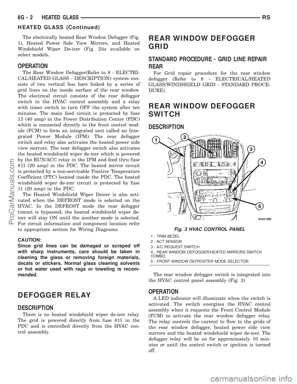
DESCRIPTION
The rear window defogger switch is integrated into
the HVAC control panel assembly (Fig. 3)
OPERATION
A LED indicator will illuminate when the switch is
activated. The switch energizes the HVAC control
assembly when it requests the Front Control Module
(FCM) to activate the rear window defogger relay.
The relay controls the current to flow to the grids of
the rear window defogger, heated power side view
mirrors and the heated windshield wiper de-icer. The
defogger relay will be on for approximately 10 min-
utes or until the control switch or ignition is turned
off.
Fig. 3 HVAC CONTROL PANEL
1 - TRIM BEZEL
2 - ACT SENSOR
3 - A/C REQUEST SWITCH
4 - REAR WINDOW DEFOGGER/HEATED MIRRORS SWITCH
COMBO
5 - FRONT WINDOW DEFROSTER MODE SELECTOR
8G - 2 HEATED GLASSRS
HEATED GLASS (Continued)
ProCarManuals.com
Page 458 of 2399

HEATED MIRRORS
TABLE OF CONTENTS
page page
HEATED MIRRORS
DESCRIPTION..........................5
OPERATION............................5
DIAGNOSIS AND TESTING - HEATED
MIRROR TEST........................5
MIRROR SWITCH
DESCRIPTION..........................5OPERATION............................6
HEATED MIRROR GRID
STANDARD PROCEDURE - HEATED MIRROR . . 6
RELAY
DESCRIPTION..........................6
HEATED MIRRORS
DESCRIPTION
Heated mirrors are available on models with
Power Mirrors and Rear Window Defogger only.
OPERATION
The heated mirror is controlled by the rear window
defogger switch. The heated mirror is ON when the
rear window defogger is ON (Fig. 1).
DIAGNOSIS AND TESTING - HEATED MIRROR
TEST
Heated mirrors are available on models with
Power Mirrors and Rear Window Defogger only. The
heated mirror is controlled by the rear window defog-
ger switch. The heated mirror is ON when the rear
window defogger is ON.
(1) The mirror glass should be warm to the touch.
(2) If not, check the 20 amp fuse (11) in the Power
Distribution Center (PDC) part of the Integrated
Power Module (IPM) in the engine compartment.
(3) Test voltage at rear window defogger switch.
²If no voltage repair wire.
²Remove mirror glass and test the wires for con-
tinuity. If no continuity repair wires.
²If wires are OK, replace mirror glass.
²To test defogger switch refer to the appropriate
section in Electrical.
MIRROR SWITCH
DESCRIPTION
The heated mirror switch is integrated into the
rear window defogger switch located in the HVAC
control panel (Fig. 1).
Fig. 1 HVAC CONTROL PANEL
1 - TRIM BEZEL
2 - ACT SENSOR
3 - A/C REQUEST SWITCH
4 - REAR WINDOW DEFOGGER/HEATED MIRRORS SWITCH
COMBO
5 - FRONT WINDOW DEFROSTER MODE SELECTOR
RSHEATED MIRRORS8G-5
ProCarManuals.com
Page 459 of 2399

OPERATION
A LED indicator will illuminate when the switch is
activated. The switch energizes the HVAC control
assembly when it requests the Front Control Module
(FCM) to activate the rear window defogger relay.
The relay controls the current to flow to the grids of
the rear window defogger and the heated power side
view mirrors. The defogger relay will be on for
approximately 10 minutes or until the control switch
or ignition is turned off.
HEATED MIRROR GRID
STANDARD PROCEDURE - HEATED MIRROR
Replacement of the mirror is necessary if the grid
is damaged and diagnostics have been performed
(Refer to 23 - BODY/EXTERIOR/SIDE VIEW MIR-
ROR - REMOVAL).
RELAY
DESCRIPTION
There is no heated mirror relay it is integrated
into the (E.B.L) relay that is located in the IPM in
the engine compartment.
8G - 6 HEATED MIRRORSRS
MIRROR SWITCH (Continued)
ProCarManuals.com
Page 504 of 2399

sage transmitted by the BCM to the FCM to turn off
the headlamps.
OPERATION
AUTOMATIC HEADLAMP SYSTEM
Automatic headlamps are controlled by the Body Con-
trol Module (BCM). With the headlamp switch in the
AUTO position, the BCM will control the headlamp, park-
ing, side marker, tail and instrumentation lamps based on
ambient light levels. Ambient light levels are monitored
by the BCM using the Day/Night signal and Electrochro-
matic Mirror (ECM) present from the Compass Mini Trip
(CMTC) located on the front windshield in front of the
rear view mirror ECM. Ambient light readings are aver-
aged to limit cycling the lamps ON and OFF when pass-
ing through areas with varying light levels. The
automatic headlamps will only function when the engine
is running with RPM > 450. When the headlamp switch is
in the AUTO position (Automatic mode), the Headlamp
Time Delay system will function when the ignition switch
is placed in any position other than run/start.
DAYTIME RUNNING LAMPS
Power is reduced using pulse-width modulation to
the high beams, where by the power is switched on
and off rapidly instead of remaining on continuously.
The duration and interval of the power pulses is pro-
grammed into the FCM.
HEADLAMP SYSTEM
The headlamp system will default to headlamps
ON position when ignition switch is ON and when an
open or short circuit failure occurs on the headlamp
switch input. The system will return to normal oper-
ation when the open or short is repaired. A fault will
be reported by the BCM when a failure occurs on the
dimmer or headlamp switch input.
If the exterior lamps are ON and the headlamp
switch is in any position other than OFF or AUTO
and with the ignition switch OFF (LOCK) after 3
minutes the BCM sends a message via PCI bus to
the FCM informing the FCM to turn off the head-
lamps, park lamps and fog lamps. This feature pre-
vents the vehicle battery from being discharged when
the vehicle lights have been left ON.
HEADLAMP TIME DELAY SYSTEM
The headlamp time delay system is activated by
turning the headlamps ON (high or low beam) while
the engine is running, turning the ignition switch
OFF, and then turning the headlamp switch OFF
within 45 seconds. The system will not activate if
more than 45 seconds elapse between ignition switch
OFF and headlamp switch OFF. The BCM will allow
the headlamps to remain ON for 90 seconds (config-urable) before they automatically turn off (If the key
is in the ignition during the headlamp time delay
mode, then both the headlamps and park lamps
(including panel dimming) will be ON). Refer to the
Owner's Manual for more information.
If the headlamp switch is in the Auto Headlamp
Position, the headlamps are ON due to the night sig-
nal from the CMTC and the ignition switch is in any
position other than run/start, the BCM shall enter a
90 second (configurable) Auto Headlamps time delay
mode. If the key is in the ignition during the head-
lamp time delay mode, then both the headlamps and
park lamps (including panel dimming) will be ON. If
the key is not in the ignition, then only the head-
lamps will be ON. The BCM will allow the head-
lamps to remain ON for 90 seconds before they
automatically turn OFF. Refer to the Owner's Man-
ual for more information.
OPTICAL HORN/HIGH BEAMS
When the multi-function switch is pulled to the
first detent (optical horn) signal, the headlamps are
ON, key-in the ignition the BCM shall send a mes-
sage via PCI bus to the FCM to turn on the head-
lamps drivers to illuminate all four filaments (Low
and High beams). When the multi-function switch is
pulled to the second detent (high beam) signal and
the headlamps are ON, the BCM shall send a mes-
sage via PCI bus to the FCM to turn on the head-
lamps drivers. The High Beams are illuminated and
the Low Beams and Fog Lamps (if ON) are extin-
guished. If the headlamps were in the high beam
configuration when power was removed from the
headlamps, the headlamps will be configured as low
beam the next time they are activated.
WARNING
WARNING: EYE PROTECTION SHOULD BE USED
WHEN SERVICING GLASS COMPONENTS. PER-
SONAL INJURY CAN RESULT.
CAUTION: Do not touch the glass of halogen bulbs
with fingers or other possibly oily surface, reduced
bulb life will result. Do not use bulbs other than
those indicated in the Bulb Application table. Dam-
age to lamp and/or Daytime Running Lamp Module
can result. Do not use fuses, circuit breakers or
relays having greater amperage value than indi-
cated on the fuse panel or in the Owners Manual.
CAUTION: Do not use bulbs other than those listed
in the Bulb Application Table. Damage to lamp can
result. Do not touch halogen bulbs with fingers or
other oily surfaces. Bulb life will be reduced.
RSLAMPS/LIGHTING - EXTERIOR8L-3
LAMPS/LIGHTING - EXTERIOR (Continued)
ProCarManuals.com
Page 517 of 2399

HEADLAMP LEVELING
SWITCH - EXPORT
DESCRIPTION
Some vehicles are equipped with a remote head-
lamp leveling system. This system allows the driver
to adjust the vertical headlamp aim from the interior
of the vehicle to compensate for passenger or cargo
load.
The headlamp leveling switch is located next to the
headlamp switch on the instrument panel (Fig. 15).
If the headlamp leveling switch is faulty or damaged,
the headlamp switch must be replaced.
DIAGNOSIS AND TESTING - HEADLAMP
LEVELING SWITCH - EXPORT
The headlamp leveling switch is located next to the
headlamp switch on the instrument panel. (Refer to 8
- ELECTRICAL/LAMPS/LIGHTING - EXTERIOR/
HEADLAMP SWITCH - DIAGNOSIS AND TEST-
ING) for diagnosis of the headlamp leveling switch. If
the headlamp leveling switch is faulty, the headlamp
switch must be replaced.
HEADLAMP SWITCH
DIAGNOSIS AND TESTING
DIAGNOSIS AND TESTING - HEADLAMP
SWITCH
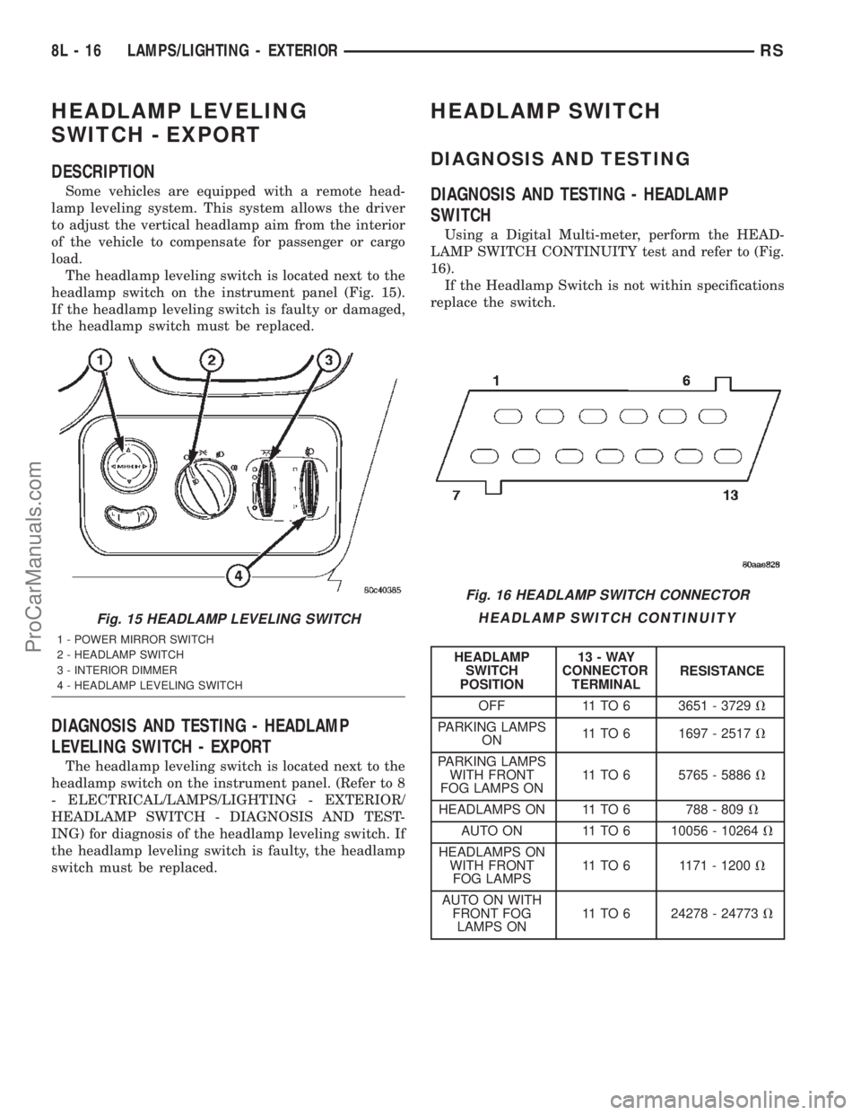
Using a Digital Multi-meter, perform the HEAD-
LAMP SWITCH CONTINUITY test and refer to (Fig.
16).
If the Headlamp Switch is not within specifications
replace the switch.
HEADLAMP SWITCH CONTINUITY
HEADLAMP
SWITCH
POSITION13-WAY
CONNECTOR
TERMINALRESISTANCE
OFF 11 TO 6 3651 - 3729V
PARKING LAMPS
ON11 TO 6 1697 - 2517V
PARKING LAMPS
WITH FRONT
FOG LAMPS ON11 TO 6 5765 - 5886V
HEADLAMPS ON 11 TO 6 788 - 809V
AUTO ON 11 TO 6 10056 - 10264V
HEADLAMPS ON
WITH FRONT
FOG LAMPS11 TO 6 1171 - 1200V
AUTO ON WITH
FRONT FOG
LAMPS ON11 TO 6 24278 - 24773V
Fig. 15 HEADLAMP LEVELING SWITCH
1 - POWER MIRROR SWITCH
2 - HEADLAMP SWITCH
3 - INTERIOR DIMMER
4 - HEADLAMP LEVELING SWITCH
Fig. 16 HEADLAMP SWITCH CONNECTOR
8L - 16 LAMPS/LIGHTING - EXTERIORRS
ProCarManuals.com
Page 542 of 2399

POWER SYSTEMS
TABLE OF CONTENTS
page page
POWER LIFTGATE SYSTEM.................. 1
POWER SLIDING DOOR SYSTEM............ 18
POWER LOCKS........................... 39POWER MIRRORS........................ 46
POWER SEAT SYSTEM..................... 51
POWER WINDOWS........................ 64
POWER LIFTGATE SYSTEM
TABLE OF CONTENTS
page page
POWER LIFTGATE SYSTEM
DESCRIPTION..........................2
OPERATION............................3
DIAGNOSIS AND TESTING - POWER
LIFTGATE SYSTEM.....................4
STANDARD PROCEDURE
STANDARD PROCEDURE - LIFTGATE
ADJUSTMENT.........................8
STANDARD PROCEDURE - POWER
LIFTGATE LEARN CYCLE................9
PINCH SENSOR
DESCRIPTION..........................9
OPERATION............................9
REMOVAL.............................9
INSTALLATION..........................9
FULL OPEN SWITCH
DESCRIPTION.........................10
OPERATION...........................10
REMOVAL.............................10
INSTALLATION.........................10
LIFTGATE MOTOR
DESCRIPTION.........................10
OPERATION...........................11
REMOVAL.............................11
INSTALLATION.........................11
ENGAGE ACTUATOR
DESCRIPTION.........................11
OPERATION...........................11
REMOVAL.............................12
INSTALLATION.........................12TRANSVERSE BRACKET
DESCRIPTION.........................12
OPERATION...........................12
REMOVAL.............................13
INSTALLATION.........................13
LIFT GEAR & LINK ROD
DESCRIPTION.........................13
OPERATION...........................14
REMOVAL.............................14
INSTALLATION.........................14
LATCH
DESCRIPTION.........................14
OPERATION...........................15
REMOVAL.............................15
INSTALLATION.........................15
LATCH ACTUATOR
DESCRIPTION.........................15
OPERATION...........................15
REMOVAL.............................15
INSTALLATION.........................16
EXTERIOR HANDLE SWITCH
DESCRIPTION.........................16
OPERATION...........................16
REMOVAL.............................16
INSTALLATION.........................16
CHIME/THERMISTOR
DESCRIPTION.........................17
OPERATION...........................17
REMOVAL.............................17
INSTALLATION.........................17
RSPOWER SYSTEMS8N-1
ProCarManuals.com