sensor CHRYSLER VOYAGER 2002 Service Manual
[x] Cancel search | Manufacturer: CHRYSLER, Model Year: 2002, Model line: VOYAGER, Model: CHRYSLER VOYAGER 2002Pages: 2399, PDF Size: 57.96 MB
Page 1929 of 2399

(6) Install coolant recovery bottle to bracket.
(7) Connect battery temperature sensor to battery
tray. Install battery tray into position (Fig. 174).
(8) Install battery, hold-down clamp, and nut (Fig.
175).(9) Install battery thermal shield (Fig. 176).
(10) Install selector cable to gearshift mechanism
(Fig. 177). Install retainer clip (Fig. 178).
Fig. 174 Battery Tray
1 - BATTERY TRAY
Fig. 175 Battery and Hold-Down Clamp
1 - BATTERY
2 - HOLD-DOWN CLAMP
Fig. 176 Battery Thermal Shield
1 - BATTERY THERMAL SHIELD
Fig. 177 Selector Cable at Gearshift Mechanism
1 - GEARSHIFT MECHANISM
2 - SELECTOR CABLE
21 - 372 T850 MANUAL TRANSAXLERS
GEARSHIFT CABLE - SELECTOR (Continued)
ProCarManuals.com
Page 1960 of 2399
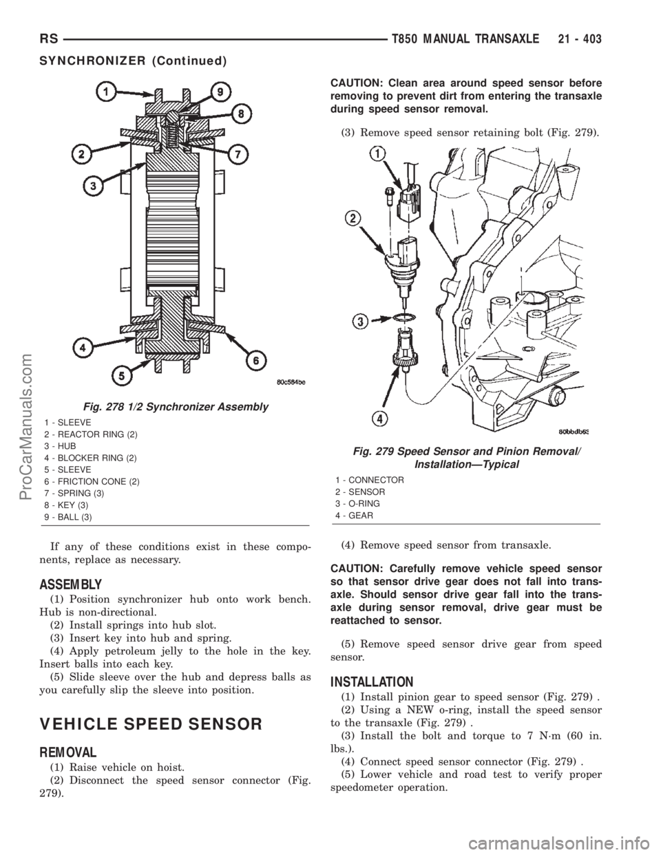
If any of these conditions exist in these compo-
nents, replace as necessary.
ASSEMBLY
(1) Position synchronizer hub onto work bench.
Hub is non-directional.
(2) Install springs into hub slot.
(3) Insert key into hub and spring.
(4) Apply petroleum jelly to the hole in the key.
Insert balls into each key.
(5) Slide sleeve over the hub and depress balls as
you carefully slip the sleeve into position.
VEHICLE SPEED SENSOR
REMOVAL
(1) Raise vehicle on hoist.
(2) Disconnect the speed sensor connector (Fig.
279).CAUTION: Clean area around speed sensor before
removing to prevent dirt from entering the transaxle
during speed sensor removal.
(3) Remove speed sensor retaining bolt (Fig. 279).
(4) Remove speed sensor from transaxle.
CAUTION: Carefully remove vehicle speed sensor
so that sensor drive gear does not fall into trans-
axle. Should sensor drive gear fall into the trans-
axle during sensor removal, drive gear must be
reattached to sensor.
(5) Remove speed sensor drive gear from speed
sensor.
INSTALLATION
(1) Install pinion gear to speed sensor (Fig. 279) .
(2) Using a NEW o-ring, install the speed sensor
to the transaxle (Fig. 279) .
(3) Install the bolt and torque to 7 N´m (60 in.
lbs.).
(4) Connect speed sensor connector (Fig. 279) .
(5) Lower vehicle and road test to verify proper
speedometer operation.
Fig. 278 1/2 Synchronizer Assembly
1 - SLEEVE
2 - REACTOR RING (2)
3 - HUB
4 - BLOCKER RING (2)
5 - SLEEVE
6 - FRICTION CONE (2)
7 - SPRING (3)
8 - KEY (3)
9 - BALL (3)
Fig. 279 Speed Sensor and Pinion Removal/
InstallationÐTypical
1 - CONNECTOR
2 - SENSOR
3 - O-RING
4 - GEAR
RST850 MANUAL TRANSAXLE21 - 403
SYNCHRONIZER (Continued)
ProCarManuals.com
Page 1962 of 2399

TIRES/WHEELS
TABLE OF CONTENTS
page page
TIRES/WHEELS
DIAGNOSIS AND TESTING - TIRE AND
WHEEL VIBRATION.....................1
STANDARD PROCEDURE
STANDARD PROCEDURE - TIRE AND
WHEEL BALANCE......................5
STANDARD PROCEDURE - TIRE AND
WHEEL MATCH MOUNTING..............5
STANDARD PROCEDURE - TIRE AND
WHEEL ROTATION.....................7
REMOVAL
REMOVAL - TIRE AND WHEEL ASSEMBLY
(ALUMINUM WHEEL)....................7
REMOVAL - TIRE AND WHEEL ASSEMBLY
(STEEL WHEEL).......................7
INSTALLATION
INSTALLATION - TIRE AND WHEEL
ASSEMBLY (ALUMINUM WHEEL)..........8
INSTALLATION - TIRE AND WHEEL
ASSEMBLY (STEEL WHEEL)..............8
TIRE PRESSURE MONITORING (TPM)
DESCRIPTION..........................9
OPERATION............................9
SENSOR - TPM
DESCRIPTION.........................10
OPERATION...........................10
CAUTION.............................10
DIAGNOSIS AND TESTING - TIRE PRESSURE
SENSOR............................10
STANDARD PROCEDURE - TIRE PRESSURE
SENSOR RETRAIN....................10
REMOVAL.............................11
INSTALLATION.........................11
TIRES
DESCRIPTION
DESCRIPTION - TIRE..................13
DESCRIPTION - RADIAL-PLY TIRES.......13DESCRIPTION - REPLACEMENT TIRES....14
DESCRIPTION - SPARE TIRE
(TEMPORARY).......................14
DIAGNOSIS AND TESTING
DIAGNOSIS AND TESTING - TIRE NOISE . . . 14
DIAGNOSIS AND TESTING - TIRE/VEHICLE
LEAD...............................14
DIAGNOSIS AND TESTING - TIRE WEAR
PATTERNS..........................14
DIAGNOSIS AND TESTING - TREAD WEAR
INDICATORS.........................14
STANDARD PROCEDURE
STANDARD PROCEDURE - TIRE INFLATION
PRESSURES.........................14
STANDARD PROCEDURE - TIRE
PRESSURE FOR HIGH SPEED
OPERATION.........................17
STANDARD PROCEDURE - TIRE LEAK
REPAIRING..........................17
CLEANING - TIRES.....................17
WHEELS
DESCRIPTION - WHEEL..................17
DIAGNOSIS AND TESTING - WHEEL
INSPECTION.........................18
CLEANING - ALUMINUM WHEEL CARE......18
SPECIFICATIONS
WHEEL.............................19
WHEEL COVER
DESCRIPTION.........................19
REMOVAL.............................19
INSTALLATION.........................19
WHEEL MOUNTING STUDS - FRONT
REMOVAL.............................20
INSTALLATION.........................21
WHEEL MOUNTING STUDS - REAR
REMOVAL.............................21
INSTALLATION.........................22
TIRES/WHEELS
DIAGNOSIS AND TESTING - TIRE AND WHEEL
VIBRATION
Tire and wheel imbalance, runout and force varia-
tion can cause vehicles to exhibit steering wheel
vibration.
VISUAL INSPECTION
Visual inspection of the vehicle is recommended
prior to road testing or performing any other proce-
dure. Raise vehicle on a suitable hoist. (Refer to
LUBRICATION & MAINTENANCE/HOISTING -
STANDARD PROCEDURE)
RSTIRES/WHEELS22-1
ProCarManuals.com
Page 1970 of 2399
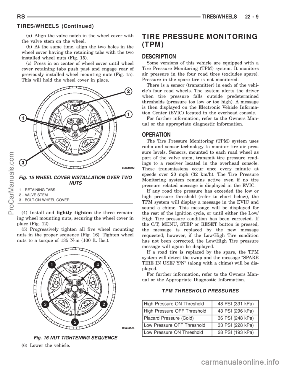
(a) Align the valve notch in the wheel cover with
the valve stem on the wheel.
(b) At the same time, align the two holes in the
wheel cover having the retaining tabs with the two
installed wheel nuts (Fig. 15).
(c) Press in on center of wheel cover until wheel
cover retaining tabs push past and engage rear of
previously installed wheel mounting nuts (Fig. 15).
This will hold the wheel cover in place.
(4) Install andlightly tightenthe three remain-
ing wheel mounting nuts, securing the wheel cover in
place (Fig. 12).
(5) Progressively tighten all five wheel mounting
nuts in the proper sequence (Fig. 16). Tighten wheel
nuts to a torque of 135 N´m (100 ft. lbs.).
(6) Lower the vehicle.TIRE PRESSURE MONITORING
(TPM)
DESCRIPTION
Some versions of this vehicle are equipped with a
Tire Pressure Monitoring (TPM) system. It monitors
air pressure in the four road tires (excludes spare).
Pressure in the spare tire is not monitored.
There is a sensor (transmitter) in each of the vehi-
cle's four road wheels. The system alerts the driver
when tire pressure falls outside predetermined
thresholds (pressure too low or too high). A message
is then displayed on the Electronic Vehicle Informa-
tion Center (EVIC) located in the overhead console.
For further information, refer to the Owners Man-
ual or the appropriate diagnostic information.
OPERATION
The Tire Pressure Monitoring (TPM) system uses
radio and sensor technology to monitor tire air pres-
sure levels. Sensors, mounted to each road wheel as
part of the valve stem, transmit tire pressure read-
ings to a receiver located in the overhead console.
These transmissions occur once every minute at
speeds over 20 mph (32 km/h). The Tire Pressure
Monitoring system remains active even if no tire
pressure related message is displayed in the EVIC.
If any road tire pressure has exceeded the low or
high pressure threshold (refer to chart below), the
TPM system will display a message in the EVIC and
sound a chime. This message will be displayed for
the rest of the ignition cycle, or until either the Low/
High Tire pressure condition has been corrected. If
the C/T, MENU, STEP or RESET button is pressed,
the message is replaced by the new message
requested; however, if the Low/High Tire condition
has not been corrected, the Low/High Tire pressure
message will again be displayed.
If a road tire is replaced by the spare, the TPM
system will detect the swap and the message9SPARE
TIRE IN USE? Y/N9(along with a chime) will be dis-
played.
For further information, refer to the Owners Man-
ual or the Appropriate Diagnostic Information.
TPM THRESHOLD PRESSURES
High Pressure ON Threshold 48 PSI (331 kPa)
High Pressure OFF Threshold 43 PSI (296 kPa)
Placard Pressure (Cold) 36 PSI (248 kPa)
Low Pressure OFF Threshold 33 PSI (228 kPa)
Low Pressure ON Threshold 28 PSI (193 kPa)
Fig. 15 WHEEL COVER INSTALLATION OVER TWO
NUTS
1 - RETAINING TABS
2 - VALVE STEM
3 - BOLT-ON WHEEL COVER
Fig. 16 NUT TIGHTENING SEQUENCE
RSTIRES/WHEELS22-9
TIRES/WHEELS (Continued)
ProCarManuals.com
Page 1971 of 2399
SENSOR - TPM
DESCRIPTION
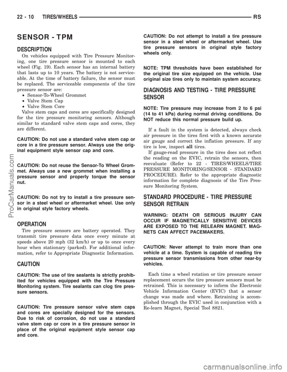
On vehicles equipped with Tire Pressure Monitor-
ing, one tire pressure sensor is mounted to each
wheel (Fig. 19). Each sensor has an internal battery
that lasts up to 10 years. The battery is not service-
able. At the time of battery failure, the sensor must
be replaced. The serviceable components of the tire
pressure sensor are:
²Sensor-To-Wheel Grommet
²Valve Stem Cap
²Valve Stem Core
Valve stem caps and cores are specifically designed
for the tire pressure monitoring sensors. Although
similar to standard valve stem caps and cores, they
are different.
CAUTION: Do not use a standard valve stem cap or
core in a tire pressure sensor. Always use the orig-
inal equipment style sensor cap and core.
CAUTION: Do not reuse the Sensor-To Wheel Grom-
met. Always use a new grommet when installing a
pressure sensor and properly torque the sensor
nut.
CAUTION: Do not try to install a tire pressure sen-
sor in a steel wheel or aftermarket wheel. Use only
in original style factory wheels.
OPERATION
Tire pressure sensors are battery operated. They
transmit tire pressure data once every minute at
speeds above 20 mph (32 km/h) or up to once every
hour when stationary (parked). For additional infor-
mation, refer to Appropriate Diagnostic Information.
CAUTION
CAUTION: The use of tire sealants is strictly prohib-
ited for vehicles equipped with the Tire Pressure
Monitoring system. Tire sealants can clog tire pres-
sure sensors.
CAUTION: Tire pressure sensor valve stem caps
and cores are specially designed for the sensors.
Due to risk of corrosion, do not use a standard
valve stem cap or core in a tire pressure sensor in
place of the original equipment style sensor cap
and core.CAUTION: Do not attempt to install a tire pressure
sensor in a steel wheel or aftermarket wheel. Use
tire pressure sensors in original style factory
wheels only.
NOTE: TPM thresholds have been established for
the original tire size equipped on the vehicle. Use
original size tires only to maintain system accuracy.
DIAGNOSIS AND TESTING - TIRE PRESSURE
SENSOR
NOTE: Tire pressure may increase from 2 to 6 psi
(14 to 41 kPa) during normal driving conditions. Do
NOT reduce this normal pressure build up.
If a fault in the system is detected, always check
air pressure in the tires first with a known accurate
air gauge and correct the inflation pressure. If any
tire is low, inspectalltires.
If gauge-read pressure in the tires does not reflect
the reading on the EVIC, retrain the sensors, then
reevaluate (Refer to 22 - TIRES/WHEELS/TIRE
PRESSURE MONITORING/SENSOR - STANDARD
PROCEDURE). Refer to the appropriate diagnostic
information for complete diagnosis of the Tire Pres-
sure Monitoring System.
STANDARD PROCEDURE - TIRE PRESSURE
SENSOR RETRAIN
WARNING: DEATH OR SERIOUS INJURY CAN
OCCUR IF MAGNETICALLY SENSITIVE DEVICES
ARE EXPOSED TO THE RELEARN MAGNET. MAG-
NETS CAN AFFECT PACEMAKERS.
CAUTION: Never attempt to train more than one
vehicle at a time. System is capable of reading tire
pressure sensor transmissions from other near-by
vehicles.
Each time a wheel rotation or tire pressure sensor
replacement occurs the tire pressure sensors must be
retrained. This is necessary to inform the Electronic
Vehicle Information Center (EVIC) that a sensor
change was made and where. Retraining is accom-
plished through the EVIC used in conjunction with a
Re-learn Magnet, Special Tool 8821.
22 - 10 TIRES/WHEELSRS
ProCarManuals.com
Page 1972 of 2399
NOTE: Use the following procedure to retrain all
four (4) road wheel tire pressure sensors. No
attempt should be made to retrain individual sen-
sors.
(1) Retrieve Re-learn Magnet, Special Tool 8821.
(2) Press MENU Button on EVIC until9RETRAIN
TIRE SENSORS - NO9is displayed.
(3) Press STEP button to select9YES9.
NOTE: There is a 60 second timer for training the
first sensor and a 30 second timer between training
the remaining sensors. If either of these timers
expire, the EVIC will abort the training procedure.
NOTE: If at any time the EVIC display reads(TRAIN-
ING ABORTED(, move the vehicle ahead at least
one foot and repeat the entire retraining procedure.
(4) Press MENU button to start retraining. Dis-
play will read9TRAIN LEFT FRONT TIRE9
NOTE: The order for retraining all five sensors is:
²Left Front
²Right Front
²Right Rear
²Left Rear
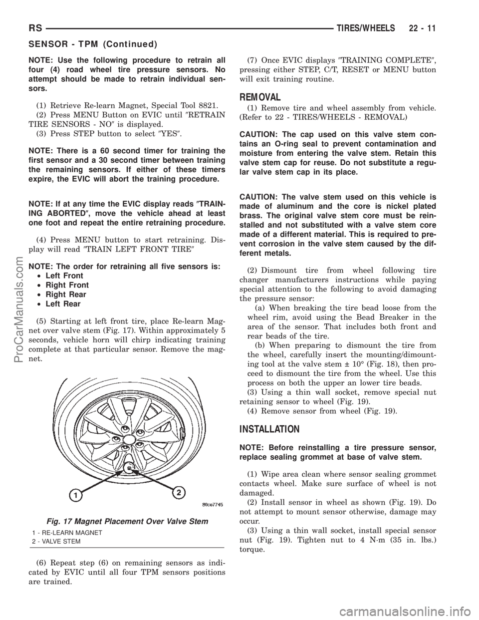
(5) Starting at left front tire, place Re-learn Mag-
net over valve stem (Fig. 17). Within approximately 5
seconds, vehicle horn will chirp indicating training
complete at that particular sensor. Remove the mag-
net.
(6) Repeat step (6) on remaining sensors as indi-
cated by EVIC until all four TPM sensors positions
are trained.(7) Once EVIC displays9TRAINING COMPLETE9,
pressing either STEP, C/T, RESET or MENU button
will exit training routine.
REMOVAL
(1) Remove tire and wheel assembly from vehicle.
(Refer to 22 - TIRES/WHEELS - REMOVAL)
CAUTION: The cap used on this valve stem con-
tains an O-ring seal to prevent contamination and
moisture from entering the valve stem. Retain this
valve stem cap for reuse. Do not substitute a regu-
lar valve stem cap in its place.
CAUTION: The valve stem used on this vehicle is
made of aluminum and the core is nickel plated
brass. The original valve stem core must be rein-
stalled and not substituted with a valve stem core
made of a different material. This is required to pre-
vent corrosion in the valve stem caused by the dif-
ferent metals.
(2) Dismount tire from wheel following tire
changer manufacturers instructions while paying
special attention to the following to avoid damaging
the pressure sensor:
(a) When breaking the tire bead loose from the
wheel rim, avoid using the Bead Breaker in the
area of the sensor. That includes both front and
rear beads of the tire.
(b) When preparing to dismount the tire from
the wheel, carefully insert the mounting/dimount-
ing tool at the valve stem 10É (Fig. 18), then pro-
ceed to dismount the tire from the wheel. Use this
process on both the upper an lower tire beads.
(3) Using a thin wall socket, remove special nut
retaining sensor to wheel (Fig. 19).
(4) Remove sensor from wheel (Fig. 19).
INSTALLATION
NOTE: Before reinstalling a tire pressure sensor,
replace sealing grommet at base of valve stem.
(1) Wipe area clean where sensor sealing grommet
contacts wheel. Make sure surface of wheel is not
damaged.
(2) Install sensor in wheel as shown (Fig. 19). Do
not attempt to mount sensor otherwise, damage may
occur.
(3) Using a thin wall socket, install special sensor
nut (Fig. 19). Tighten nut to 4 N´m (35 in. lbs.)
torque.
Fig. 17 Magnet Placement Over Valve Stem
1 - RE-LEARN MAGNET
2 - VALVE STEM
RSTIRES/WHEELS22-11
SENSOR - TPM (Continued)
ProCarManuals.com
Page 1973 of 2399

CAUTION: Over-torquing the sensor nut by as little
as 12 N´m (106 in. lbs.) may result in sensor sepa-
ration from the valve stem. Under this condition,
the sensor may still function, however, the condi-
tion should be corrected immediately.(4) Mount tire on wheel following tire changer
manufacturers instructions, paying special attention
to the following to avoid damaging tire pressure sen-
sor:
(a) Rotating Wheel Tire Changers - Once the
wheel is mounted to the changer, position the sen-
sor valve stem approximately 210É from the head
of the changer in a clockwise direction before rotat-
ing the wheel (also in a clockwise direction) to
mount the tire (Fig. 20). Use this procedure on
both the upper and lower tire beads.
(b) Rotating Tool Tire Changers - Position the
wheel on the changer so that the sensor valve stem
is approximately 210É from the head of the changer
in a clockwise direction from the mounting end of
the tool (Fig. 21) Make sure the sensor is clear of
the lower bead breaker area to avoid damaging the
sensor when the breaker rises (Fig. 21). Rotate the
tool in a counterclockwise direction to mount the
tire. Use this procedure on both the upper and
lower tire beads.
(5) Install wheel and tire assembly on vehicle.
(Refer to 22 - TIRES/WHEELS - INSTALLATION)
Fig. 18 Start Mount/Dismount Tool Within 10
Degrees Of Valve Stem
Fig. 19 Sensor Mounting To Wheel
1 - TIRE PRESSURE SENSOR
2 - WHEEL
3 - NUT
Fig. 20 Mounting Tire Using Rotating Wheel
Machine
1 - HEAD OF CHANGER LOCATED HERE
2 - VALVE STEM
22 - 12 TIRES/WHEELSRS
SENSOR - TPM (Continued)
ProCarManuals.com
Page 1974 of 2399
(6) Retrain tire pressure sensors. (Refer to 22 -
TIRES/WHEELS/TIRE PRESSURE MONITORING/
SENSOR - STANDARD PROCEDURE)
TIRES
DESCRIPTION
DESCRIPTION - TIRE
Tires are designed and engineered for each specific
vehicle. They provide the best overall performance
for normal operation. The ride and handling charac-
teristics match the vehicle's requirements. With
proper care they will give excellent reliability, trac-
tion, skid resistance, and tread life.
Driving habits have more effect on tire life than
any other factor. Careful drivers will obtain, in most
cases, much greater mileage than severe use or care-
less drivers. A few of the driving habits which will
shorten the life of any tire are:
²Rapid acceleration
²Severe application of brakes
²High-speed driving
²Taking turns at excessive speeds
²Striking curbs and other obstacles
²Operating vehicle with over or under inflated
tire pressuresRadial ply tires are more prone to irregular tread
wear. It is important to follow the tire rotation inter-
val shown in the section on Tire Rotation. This will
help to achieve a greater tread-life potential.
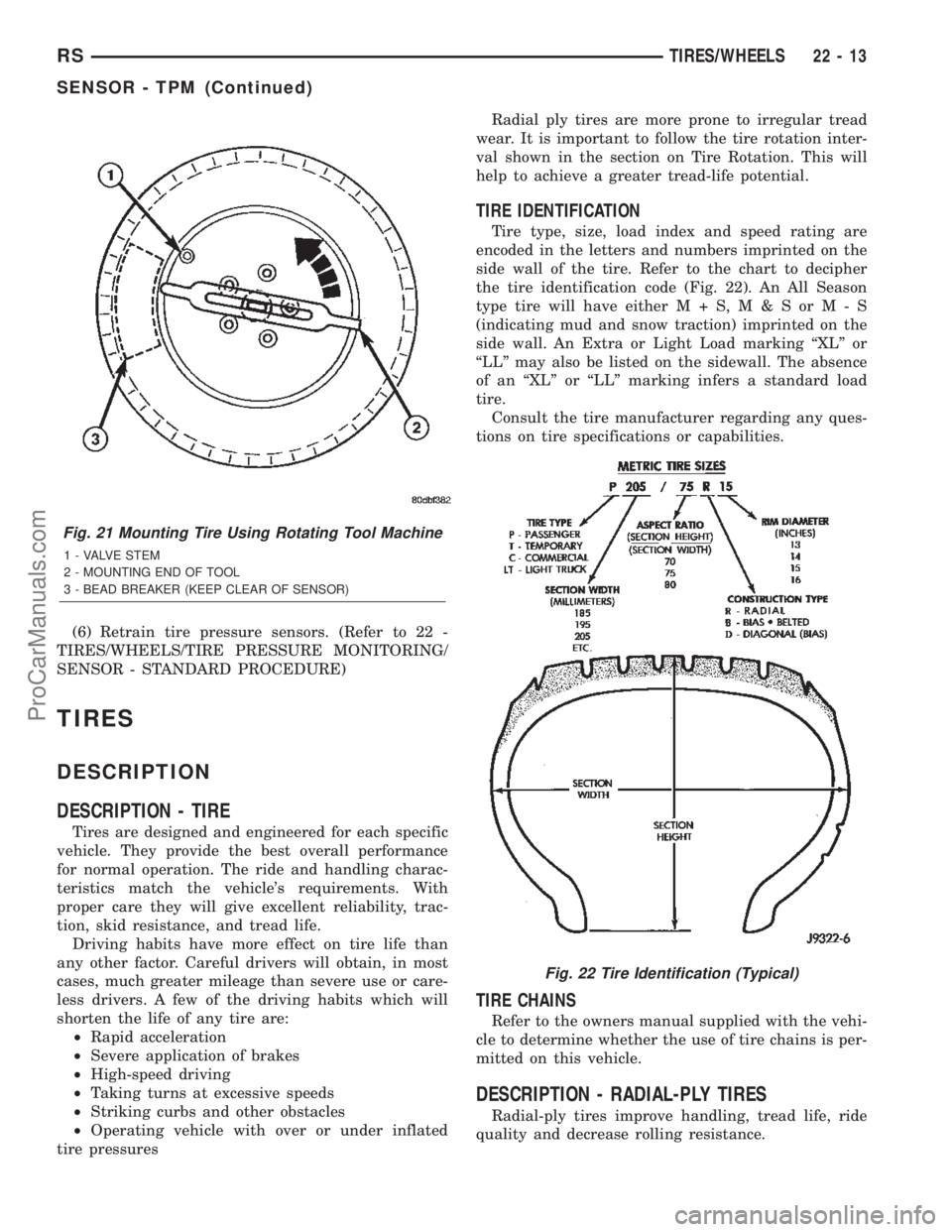
TIRE IDENTIFICATION
Tire type, size, load index and speed rating are
encoded in the letters and numbers imprinted on the
side wall of the tire. Refer to the chart to decipher
the tire identification code (Fig. 22). An All Season
type tire will have eitherM+S,M&SorM-S
(indicating mud and snow traction) imprinted on the
side wall. An Extra or Light Load marking ªXLº or
ªLLº may also be listed on the sidewall. The absence
of an ªXLº or ªLLº marking infers a standard load
tire.
Consult the tire manufacturer regarding any ques-
tions on tire specifications or capabilities.
TIRE CHAINS
Refer to the owners manual supplied with the vehi-
cle to determine whether the use of tire chains is per-
mitted on this vehicle.
DESCRIPTION - RADIAL-PLY TIRES
Radial-ply tires improve handling, tread life, ride
quality and decrease rolling resistance.
Fig. 21 Mounting Tire Using Rotating Tool Machine
1 - VALVE STEM
2 - MOUNTING END OF TOOL
3 - BEAD BREAKER (KEEP CLEAR OF SENSOR)
Fig. 22 Tire Identification (Typical)
RSTIRES/WHEELS22-13
SENSOR - TPM (Continued)
ProCarManuals.com
Page 2245 of 2399

FRONT CONTROL PANEL
The front control panel and integral computer is
mounted in the instrument panel.
The instrument panel mounted control and inte-
gral computer contains:
²a power button which allows the system to be
completely turned off.
²rear window defogger on/off switch.
²slide controls for completely independent side-to-
side temperature control of the discharge air. The full
range of temperature that the system can produce in
any mode is available on either side of the vehicle by
independently positioning the slide controls on the
instrument panel.
²air recirculation button. The Recirculate button
contains an LED that illuminates to show when the
function is in operation.
²an air conditioning button that allows the com-
pressor to be turned on/off. The Snowflake button
contains an LED that illuminates to shown when the
function is in operation.
²rotary knobs for front and rear fan speed selec-
tion.
²a rotary knob for mode control.
REAR CONTROL PANEL
A rear control panel centrally mounted on the
headliner has a rotary adjustment for temperature
and fan speed control of the rear unit by intermedi-
ate seat passengers when the front control rear knob
is set to the rear position.
DESCRIPTION - THREE ZONE AUTOMATIC
TEMPERATURE CONTROL
The Three-Zone Automatic Temperature Control
(ATC) allows occupants to select a comfort tempera-
ture, which is the perceived temperature level not
the actual passenger compartment air temperature.
The Three Zone Automatic Temperature Control
system includes a dust and odor air filter. The filter
element is the same size as the air conditioning evap-
orator to ensure ample capacity. A door at the base of
the heater and air conditioning housing below the
glove box provides easy access to the filter element.
The ATC computer utilizes integrated circuitry and
information carried on the Programmable Communi-
cations Interface (PCI) data bus network to monitor
many sensors and switch inputs throughout the vehi-
cle. In response to those inputs, the internal circuitry
and programming of the ATC computer allow it to
control electronic functions and features of the ATC
system. The inputs to the ATC computer are:
²Vehicle Speed/Engine RPM± The ATC com-
puter monitors engine RPM, vehicle speed and Man-
ifold Absolute Pressure information from the PCM.²Coolant Temperature± ATC computer moni-
tors Coolant temperature received from the PCM and
converts it to degrees Fahrenheit.
²Ambient Temperature± ATC computer moni-
tors Ambient temperature from the Compass Mini
Trip Computer (CMTC) and converts it to degrees
Fahrenheit.
²Engine Miscellaneous Sensor Status±ATC
computer monitors A/C disable information from the
PCM.
²Refrigerant Pressure± ATC computer moni-
tors Barometric Pressure, Intake Air Temperature,
High Side Pressure and Methanol Content as broad-
cast by the PCM.
²Door Ajar Status± The ATC computer moni-
tors Driver Front Door, Passenger Front Door, Left
Rear Door, Right Rear Door and Liftgate ajar infor-
mation, as identified by the Body Control Module
(BCM), to determine if all in-car temperatures should
be maintained.
²Dimming± The ATC computer monitors dim-
ming status from the BCM to determine the required
level of brightness and will dim accordingly.
²Vehicle Odometer± The ATC computer moni-
tors the vehicle odometer information from the BCM
to prevent flashing the VF tube icons if the manual
motor calibration or manual cool down tests have
failed. Flashing of the display icons will cease when
the vehicle odometer is greater than 3 miles.
²English Metric± The ATC computer monitors
the English/Metric information broadcast by the
CMTC. The set temp displays for both the front and
rear control heads will be set accordingly.
²Vehicle Identification Number± The ATC
computer monitors the last eight characters of the
VIN broadcast by the PCM and compares it to the
information stored in EEPROM. If it is different, the
new number will be stored over the old one and a
motor calibration shall be initiated.
²A/C System Information± The ATC computer
will send a message for Evaporator Temperature too
Low, Fan Blower Relay status, Evaporator Sensor
Failure, Rear Window Defogger Relay and A/C Select.
FRONT CONTROL PANEL
The front control panel and integral computer is
mounted in the instrument panel.
The instrument panel mounted control and inte-
gral computer contains:
²A power button which allows the system to be
completely turned off. The display is blank when the
system is off.
²Three rocker switches that select comfort tem-
peratures from 15É to 30É C (59É to 85É F), which are
shown in the vacuum-fluorescent digital control dis-
play. If the set temp is 59 and the down button is
24 - 2 HEATING & AIR CONDITIONINGRS
HEATING & AIR CONDITIONING (Continued)
ProCarManuals.com
Page 2247 of 2399

REAR CONTROL PANEL
With the rear control active, temperature selection
dictates indirectly the mode (floor or overhead air) of
the rear unit: a low temperature setting directs flow
to the overhead outlets and a high temperature set-
ting to the floor.
OPERATION - THREE ZONE ATC
Comfort temperature or perceived temperature is
affected by air flow, sun impinging on exposed skin,
etc. The air temperature may be higher or lower than
the comfort temperature. Three infrared sensors, two
in the instrument panel center stack, and one in the
overhead-mounted rear control panel, independently
measure the temperature of the driver, front passen-
ger, and rear compartment occupants to determine
their comfort level relative to the selected comfort
temperature. The HVAC computer in the control
module adjusts the air flow rate and temperature to
maintain the customer-perceived comfort tempera-
ture. The air temperature in the passenger compart-
ment at any time may be slightly higher or lower
than the comfort temperature. For instance, on
sunny summer days the air flow will probably be
cooler than the comfort temperature; on cold or
cloudy days and at night it will probably be slightly
warmer. Infrared Three-Zone Temperature Control
provides side-to-side and front-to-rear variation in
comfort temperature settings. The Infrared Three-
Zone Automatic Temperature Control fan provides a
continuously variable air flow rate to meet occupant
comfort requirements.
FRONT CONTROL PANEL
²AUTO HI/LO± This system features two sets of
automatic control logic that allow either a rapid cool-
down rate or a somewhat slower cool-down rate with
less fan noise. HI-AUTO controls the system to reach
its assigned temperature quickly with a higher fan
speed. LO-AUTO controls the system to reach its
assigned temperature somewhat slower with less fan
noise. Both modes will automatically engage auto
recirculation.
²DE-FROST± The front de-frost function is
active when the rear window defogger function is
active or when the defog/defrost mode is selected.
²RECIRC± The RECIRC button will close the
air inlet door. If the system is in auto recirc (indica-
tor being displayed automatically), pressing the man-
ual recirc button will disable the auto recirc function
until one of the auto keys are pressed or the ignition
is cycled. If Auto HI/LO is pressed while manual
recirc is active, manual recirc will be deactivated.
²REAR WINDOW DEFOGGER± Pushing the
button sends a PCI bus message to the Intelligent
Power Module which controls the Rear WindowDefogger and side view mirror (if equipped) circuitry.
The defogger function will be active for 10 minutes
and can be turned off by a switch press. The defogger
will function while the control is in the OFF mode.
²FAN/MODE± The Fan and Mode knobs have
17 manual selectable positions. Manually changing
either of the rotary knobs for mode or fan speed set-
tings makes control of that function alone manual for
as long as the ignition is on. If only one is changed
manually, the other remains under automatic control.
Pressing the HI-AUTO/LO-AUTO rocker switch
restores full automatic control.
²REAR CONTROL± When the Rear System
control knob is moved to the OFF position, there will
be a delay of approximately 1 second before the sys-
tem actually turns off. This delay is to prevent an
undesired blower dropout if the knob is moved
through OFF to the other selections.
²BLOWER DELAY TIMER± The word DELAY
is displayed at start-up to signify that the system is
waiting so that cold air will not be blowing. This tells
the operator that it is unnecessary to turn the sys-
tem off, raise the temperature setting or turn the fan
speed setting down to prevent cold air from blowing.
A countdown in minutes and seconds until the engine
is warm enough to begin delivering heat to the pas-
sengers alternates with the DELAY message at 25
second intervals. This countdown is based on actual
measurement of the rate of engine coolant tempera-
ture change. During the delay time, Defrost mode is
selected and the fan operates at a low speed to keep
the windshield fog free.
REAR CONTROL PANEL
Primary control of the rear compartment unit is in
the instrument panel center stack. The rear unit con-
trol knob there allows the driver to turn the rear
unit off, allow control by the intermediate seat occu-
pants by switching to the REAR position, or provide
fully automatic control based on the temperature set-
ting shown on the front control display.
²REAR CONTROL± Selecting automatic control
of the rear unit at the instrument panel, illuminates
a Locked Padlock in the rear control panel display.
Selecting REAR activates the rear control panel and
the Padlock then appears unlocked.
²FAN KNOB± The rear fan control has Off and
AUTO positions and a range of manual speed set-
tings that override the AUTO setting.
²MODE KNOB± The mode control allows inter-
mediate seat occupants to manually override the
automatic mode and select any balance of air flow
between overhead and floor outlets from full over-
head to full floor.
²SET TEMP± The rear set temp control will
operate identical to the front controls. If the front
24 - 4 HEATING & AIR CONDITIONINGRS
HEATING & AIR CONDITIONING (Continued)
ProCarManuals.com