sensor CHRYSLER VOYAGER 2002 Service Manual
[x] Cancel search | Manufacturer: CHRYSLER, Model Year: 2002, Model line: VOYAGER, Model: CHRYSLER VOYAGER 2002Pages: 2399, PDF Size: 57.96 MB
Page 1772 of 2399
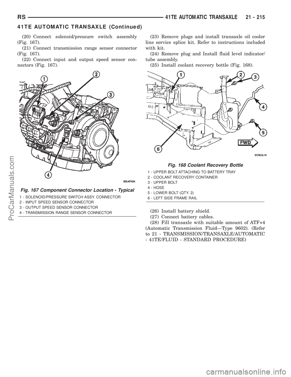
(20) Connect solenoid/pressure switch assembly
(Fig. 167).
(21) Connect transmission range sensor connector
(Fig. 167).
(22) Connect input and output speed sensor con-
nectors (Fig. 167).(23) Remove plugs and install transaxle oil cooler
line service splice kit. Refer to instructions included
with kit.
(24) Remove plug and Install fluid level indicator/
tube assembly.
(25) Install coolant recovery bottle (Fig. 168).
(26) Install battery shield.
(27) Connect battery cables.
(28) Fill transaxle with suitable amount of ATF+4
(Automatic Transmission FluidÐType 9602). (Refer
to 21 - TRANSMISSION/TRANSAXLE/AUTOMATIC
- 41TE/FLUID - STANDARD PROCEDURE)
Fig. 167 Component Connector Location - Typical
1 - SOLENOID/PRESSURE SWITCH ASSY. CONNECTOR
2 - INPUT SPEED SENSOR CONNECTOR
3 - OUTPUT SPEED SENSOR CONNECTOR
4 - TRANSMISSION RANGE SENSOR CONNECTOR
Fig. 168 Coolant Recovery Bottle
1 - UPPER BOLT ATTACHING TO BATTERY TRAY
2 - COOLANT RECOVERY CONTAINER
3 - UPPER BOLT
4 - HOSE
5 - LOWER BOLT (QTY. 2)
6 - LEFT SIDE FRAME RAIL
RS41TE AUTOMATIC TRANSAXLE21 - 215
41TE AUTOMATIC TRANSAXLE (Continued)
ProCarManuals.com
Page 1786 of 2399
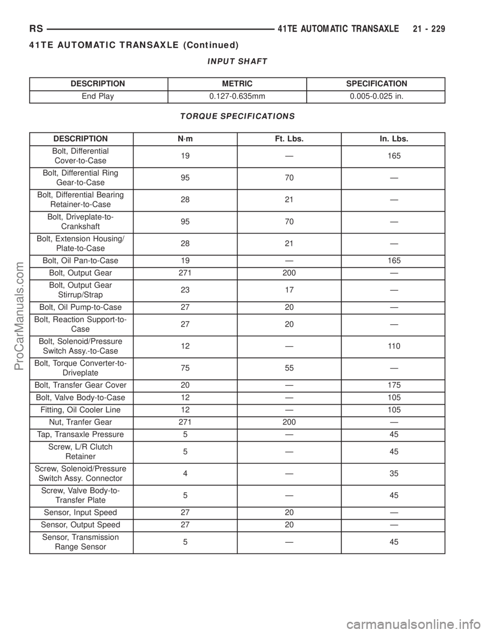
INPUT SHAFT
DESCRIPTION METRIC SPECIFICATION
End Play 0.127-0.635mm 0.005-0.025 in.
TORQUE SPECIFICATIONS
DESCRIPTION N´m Ft. Lbs. In. Lbs.
Bolt, Differential
Cover-to-Case19 Ð 165
Bolt, Differential Ring
Gear-to-Case95 70 Ð
Bolt, Differential Bearing
Retainer-to-Case28 21 Ð
Bolt, Driveplate-to-
Crankshaft95 70 Ð
Bolt, Extension Housing/
Plate-to-Case28 21 Ð
Bolt, Oil Pan-to-Case 19 Ð 165
Bolt, Output Gear 271 200 Ð
Bolt, Output Gear
Stirrup/Strap23 17 Ð
Bolt, Oil Pump-to-Case 27 20 Ð
Bolt, Reaction Support-to-
Case27 20 Ð
Bolt, Solenoid/Pressure
Switch Assy.-to-Case12 Ð 110
Bolt, Torque Converter-to-
Driveplate75 55 Ð
Bolt, Transfer Gear Cover 20 Ð 175
Bolt, Valve Body-to-Case 12 Ð 105
Fitting, Oil Cooler Line 12 Ð 105
Nut, Tranfer Gear 271 200 Ð
Tap, Transaxle Pressure 5 Ð 45
Screw, L/R Clutch
Retainer5Ð45
Screw, Solenoid/Pressure
Switch Assy. Connector4Ð35
Screw, Valve Body-to-
Transfer Plate5Ð45
Sensor, Input Speed 27 20 Ð
Sensor, Output Speed 27 20 Ð
Sensor, Transmission
Range Sensor5Ð45
RS41TE AUTOMATIC TRANSAXLE21 - 229
41TE AUTOMATIC TRANSAXLE (Continued)
ProCarManuals.com
Page 1806 of 2399
FLUID
STANDARD PROCEDURE
FLUID LEVEL AND CONDITION CHECK
NOTE: Only transmission fluid of the type labeled
Mopar ATF+4 (Automatic Transmission Fluid±Type
9602) should be used in this transaxle.
FLUID LEVEL CHECK
The transmission sump has a fluid level indicator
(dipstick) to check oil similar to most automatic
transmissions. It is located on the left side of the
engine. Be sure to wipe all dirt from dipstick handle
before removing.
The torque converter fills in both the P Park and N
Neutral positions. Place the selector lever in P Park
to be sure that the fluid level check is accurate.The
engine should be running at idle speed for at
least one minute, with the vehicle on level
ground.At normal operating temperature 82É C
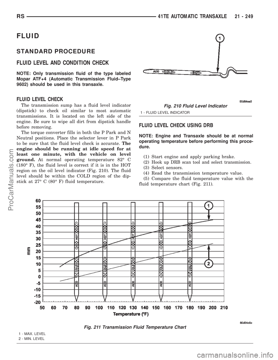
(180É F), the fluid level is correct if it is in the HOT
region on the oil level indicator (Fig. 210). The fluid
level should be within the COLD region of the dip-
stick at 27É C (80É F) fluid temperature.
FLUID LEVEL CHECK USING DRB
NOTE: Engine and Transaxle should be at normal
operating temperature before performing this proce-
dure.
(1) Start engine and apply parking brake.
(2)
Hook up DRB scan tool and select transmission.
(3) Select sensors.
(4) Read the transmission temperature value.
(5) Compare the fluid temperature value with the
fluid temperature chart (Fig. 211).
Fig. 210 Fluid Level Indicator
1 - FLUID LEVEL INDICATOR
Fig. 211 Transmission Fluid Temperature Chart
1 - MAX. LEVEL
2 - MIN. LEVEL
RS41TE AUTOMATIC TRANSAXLE21 - 249
ProCarManuals.com
Page 1837 of 2399
OPERATION
SOLENOIDS
The solenoids receive electrical power from the
Transmission Control Relay through a single wire.
The TCM energizes or operates the solenoids individ-
ually by grounding the return wire of the solenoid
needed. When a solenoid is energized, the solenoid
valve shifts, and a fluid passage is opened or closed
(vented or applied), depending on its default operat-
ing state. The result is an apply or release of a fric-
tional element.
The 2/4 and UD solenoids are normally applied,
which by design allow fluid to pass through in their
relaxed or ªoffº state. This allows transaxle limp-in
(P,R,N,2) in the event of an electrical failure.
The continuity of the solenoids and circuits are
periodically tested. Each solenoid is turned on or off
depending on its current state. An inductive spike
should be detected by the TCM during this test. It no
spike is detected, the circuit is tested again to verify
the failure. In addition to the periodic testing, the
solenoid circuits are tested if a speed ratio or pres-
sure switch error occurs.
PRESSURE SWITCHES
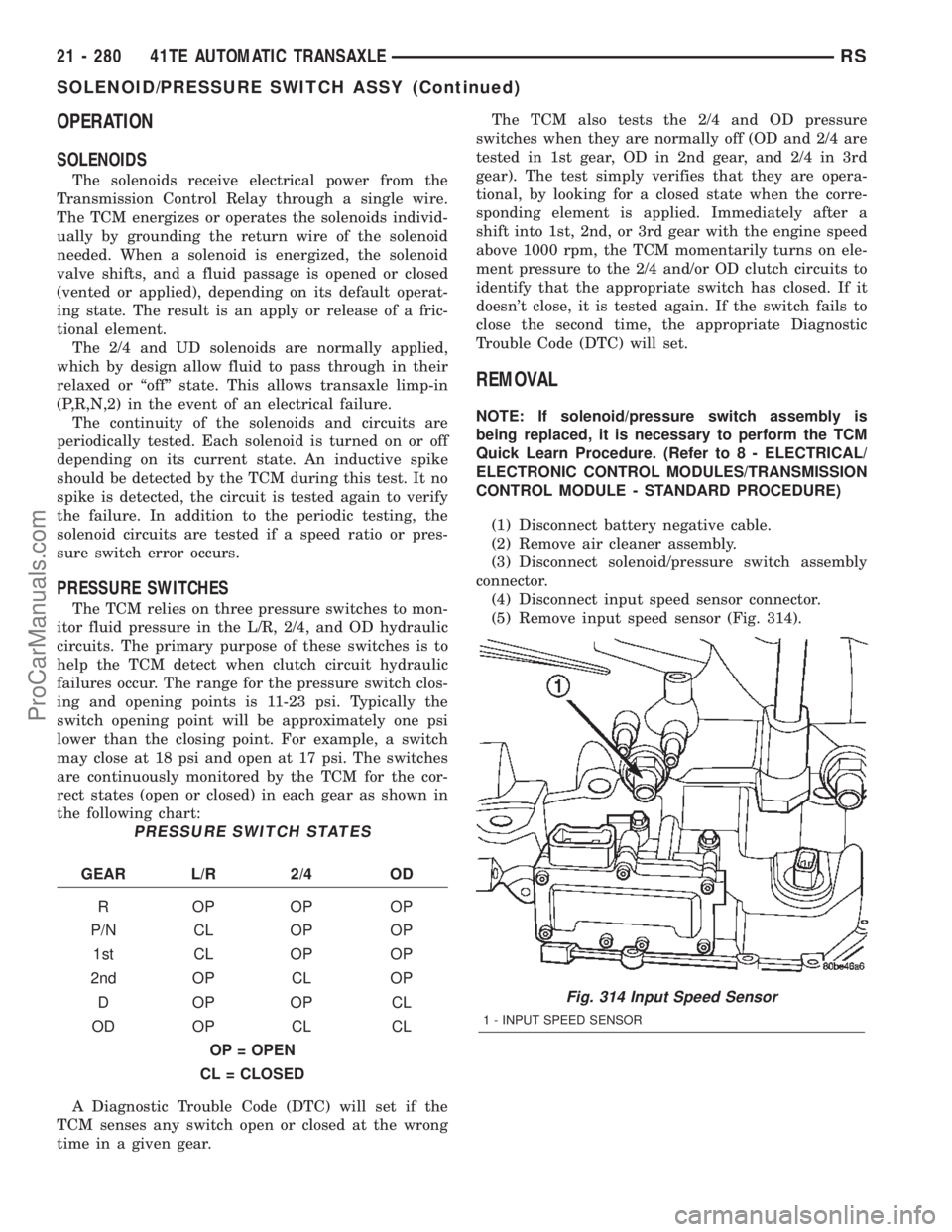
The TCM relies on three pressure switches to mon-
itor fluid pressure in the L/R, 2/4, and OD hydraulic
circuits. The primary purpose of these switches is to
help the TCM detect when clutch circuit hydraulic
failures occur. The range for the pressure switch clos-
ing and opening points is 11-23 psi. Typically the
switch opening point will be approximately one psi
lower than the closing point. For example, a switch
may close at 18 psi and open at 17 psi. The switches
are continuously monitored by the TCM for the cor-
rect states (open or closed) in each gear as shown in
the following chart:
PRESSURE SWITCH STATES
GEAR L/R 2/4 OD
ROPOPOP
P/N CL OP OP
1st CL OP OP
2nd OP CL OP
DOPOPCL
OD OP CL CL
OP = OPEN
CL = CLOSED
A Diagnostic Trouble Code (DTC) will set if the
TCM senses any switch open or closed at the wrong
time in a given gear.The TCM also tests the 2/4 and OD pressure
switches when they are normally off (OD and 2/4 are
tested in 1st gear, OD in 2nd gear, and 2/4 in 3rd
gear). The test simply verifies that they are opera-
tional, by looking for a closed state when the corre-
sponding element is applied. Immediately after a
shift into 1st, 2nd, or 3rd gear with the engine speed
above 1000 rpm, the TCM momentarily turns on ele-
ment pressure to the 2/4 and/or OD clutch circuits to
identify that the appropriate switch has closed. If it
doesn't close, it is tested again. If the switch fails to
close the second time, the appropriate Diagnostic
Trouble Code (DTC) will set.
REMOVAL
NOTE: If solenoid/pressure switch assembly is
being replaced, it is necessary to perform the TCM
Quick Learn Procedure. (Refer to 8 - ELECTRICAL/
ELECTRONIC CONTROL MODULES/TRANSMISSION
CONTROL MODULE - STANDARD PROCEDURE)
(1) Disconnect battery negative cable.
(2) Remove air cleaner assembly.
(3) Disconnect solenoid/pressure switch assembly
connector.
(4) Disconnect input speed sensor connector.
(5) Remove input speed sensor (Fig. 314).
Fig. 314 Input Speed Sensor
1 - INPUT SPEED SENSOR
21 - 280 41TE AUTOMATIC TRANSAXLERS
SOLENOID/PRESSURE SWITCH ASSY (Continued)
ProCarManuals.com
Page 1838 of 2399
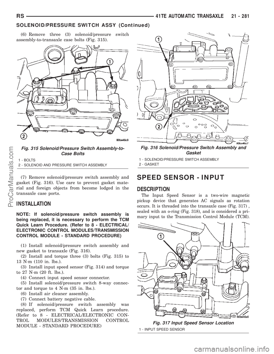
(6) Remove three (3) solenoid/pressure switch
assembly-to-transaxle case bolts (Fig. 315).
(7) Remove solenoid/pressure switch assembly and
gasket (Fig. 316). Use care to prevent gasket mate-
rial and foreign objects from become lodged in the
transaxle case ports.
INSTALLATION
NOTE: If solenoid/pressure switch assembly is
being replaced, it is necessary to perform the TCM
Quick Learn Procedure. (Refer to 8 - ELECTRICAL/
ELECTRONIC CONTROL MODULES/TRANSMISSION
CONTROL MODULE - STANDARD PROCEDURE)
(1) Install solenoid/pressure switch assembly and
new gasket to transaxle (Fig. 316).
(2) Install and torque three (3) bolts (Fig. 315) to
13 N´m (110 in. lbs.).
(3) Install input speed sensor (Fig. 314) and torque
to 27 N´m (20 ft. lbs.).
(4) Connect input speed sensor connector.
(5) Install solenoid/pressure switch 8-way connec-
tor and torque to 4 N´m (35 in. lbs.).
(6) Install air cleaner assembly.
(7) Connect battery negative cable.
(8) If solenoid/pressure switch assembly was
replaced, perform TCM Quick Learn procedure.
(Refer to 8 - ELECTRICAL/ELECTRONIC CON-
TROL MODULES/TRANSMISSION CONTROL
MODULE - STANDARD PROCEDURE)
SPEED SENSOR - INPUT
DESCRIPTION
The Input Speed Sensor is a two-wire magnetic
pickup device that generates AC signals as rotation
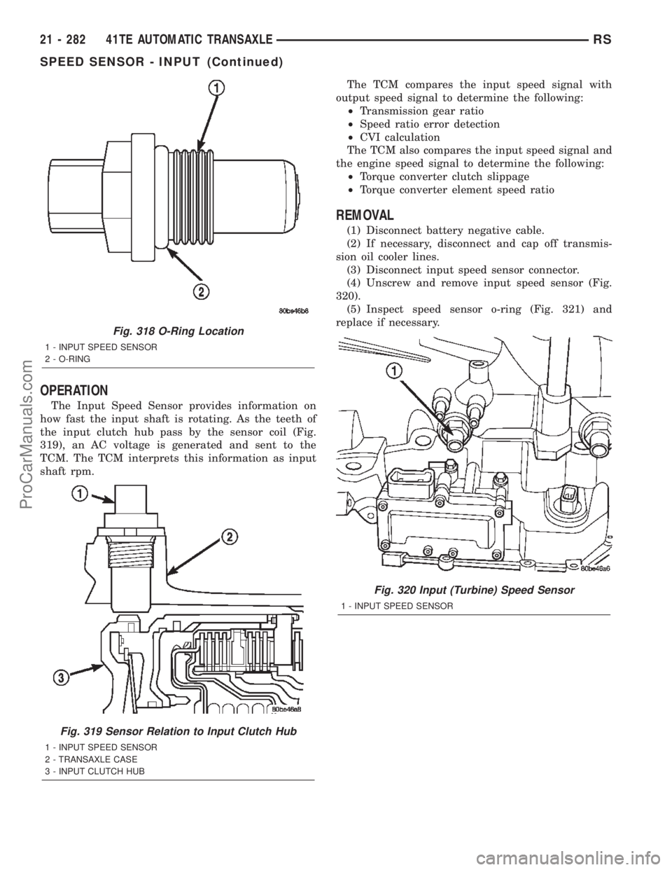
occurs. It is threaded into the transaxle case (Fig. 317) ,
sealed with an o-ring (Fig. 318), and is considered a pri-
mary input to the Transmission Control Module (TCM).
Fig. 315 Solenoid/Pressure Switch Assembly-to-
Case Bolts
1 - BOLTS
2 - SOLENOID AND PRESSURE SWITCH ASSEMBLY
Fig. 316 Solenoid/Pressure Switch Assembly and
Gasket
1 - SOLENOID/PRESSURE SWITCH ASSEMBLY
2 - GASKET
Fig. 317 Input Speed Sensor Location
1 - INPUT SPEED SENSOR
RS41TE AUTOMATIC TRANSAXLE21 - 281
SOLENOID/PRESSURE SWITCH ASSY (Continued)
ProCarManuals.com
Page 1839 of 2399
OPERATION
The Input Speed Sensor provides information on
how fast the input shaft is rotating. As the teeth of
the input clutch hub pass by the sensor coil (Fig.
319), an AC voltage is generated and sent to the
TCM. The TCM interprets this information as input
shaft rpm.The TCM compares the input speed signal with
output speed signal to determine the following:
²Transmission gear ratio
²Speed ratio error detection
²CVI calculation
The TCM also compares the input speed signal and
the engine speed signal to determine the following:
²Torque converter clutch slippage
²Torque converter element speed ratio
REMOVAL
(1) Disconnect battery negative cable.
(2) If necessary, disconnect and cap off transmis-
sion oil cooler lines.
(3) Disconnect input speed sensor connector.
(4) Unscrew and remove input speed sensor (Fig.
320).
(5) Inspect speed sensor o-ring (Fig. 321) and
replace if necessary.
Fig. 318 O-Ring Location
1 - INPUT SPEED SENSOR
2 - O-RING
Fig. 319 Sensor Relation to Input Clutch Hub
1 - INPUT SPEED SENSOR
2 - TRANSAXLE CASE
3 - INPUT CLUTCH HUB
Fig. 320 Input (Turbine) Speed Sensor
1 - INPUT SPEED SENSOR
21 - 282 41TE AUTOMATIC TRANSAXLERS
SPEED SENSOR - INPUT (Continued)
ProCarManuals.com
Page 1840 of 2399
INSTALLATION
(1) Verify o-ring is installed into position.
(2) Install and tighten input speed sensor to 27
N´m (20 ft. lbs.).
(3) Connect speed sensor connector.
(4) Connect battery negative cable.
SPEED SENSOR - OUTPUT
DESCRIPTION
The Output Speed Sensor is a two-wire magnetic
pickup device that generates an AC signal as rotation
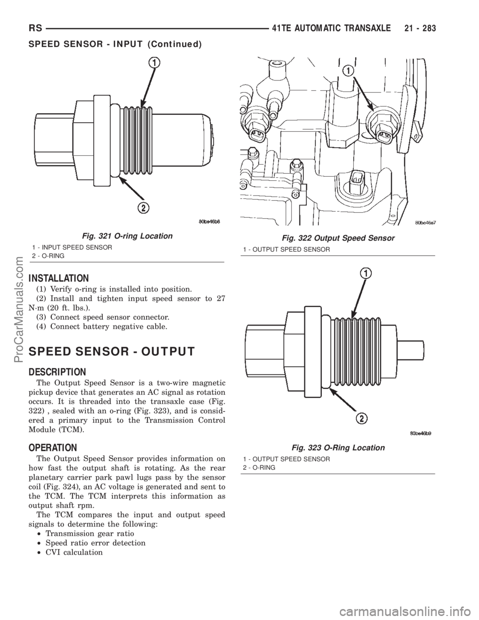
occurs. It is threaded into the transaxle case (Fig.
322) , sealed with an o-ring (Fig. 323), and is consid-
ered a primary input to the Transmission Control
Module (TCM).
OPERATION
The Output Speed Sensor provides information on
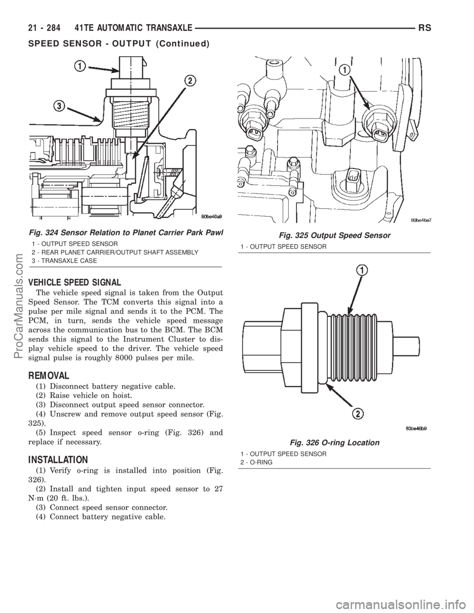
how fast the output shaft is rotating. As the rear
planetary carrier park pawl lugs pass by the sensor
coil (Fig. 324), an AC voltage is generated and sent to
the TCM. The TCM interprets this information as
output shaft rpm.
The TCM compares the input and output speed
signals to determine the following:
²Transmission gear ratio
²Speed ratio error detection
²CVI calculation
Fig. 321 O-ring Location
1 - INPUT SPEED SENSOR
2 - O-RING
Fig. 322 Output Speed Sensor
1 - OUTPUT SPEED SENSOR
Fig. 323 O-Ring Location
1 - OUTPUT SPEED SENSOR
2 - O-RING
RS41TE AUTOMATIC TRANSAXLE21 - 283
SPEED SENSOR - INPUT (Continued)
ProCarManuals.com
Page 1841 of 2399
VEHICLE SPEED SIGNAL
The vehicle speed signal is taken from the Output
Speed Sensor. The TCM converts this signal into a
pulse per mile signal and sends it to the PCM. The
PCM, in turn, sends the vehicle speed message
across the communication bus to the BCM. The BCM
sends this signal to the Instrument Cluster to dis-
play vehicle speed to the driver. The vehicle speed
signal pulse is roughly 8000 pulses per mile.
REMOVAL
(1) Disconnect battery negative cable.
(2) Raise vehicle on hoist.
(3) Disconnect output speed sensor connector.
(4) Unscrew and remove output speed sensor (Fig.
325).
(5) Inspect speed sensor o-ring (Fig. 326) and
replace if necessary.
INSTALLATION
(1) Verify o-ring is installed into position (Fig.
326).
(2) Install and tighten input speed sensor to 27
N´m (20 ft. lbs.).
(3) Connect speed sensor connector.
(4) Connect battery negative cable.
Fig. 324 Sensor Relation to Planet Carrier Park Pawl
1 - OUTPUT SPEED SENSOR
2 - REAR PLANET CARRIER/OUTPUT SHAFT ASSEMBLY
3 - TRANSAXLE CASE
Fig. 325 Output Speed Sensor
1 - OUTPUT SPEED SENSOR
Fig. 326 O-ring Location
1 - OUTPUT SPEED SENSOR
2 - O-RING
21 - 284 41TE AUTOMATIC TRANSAXLERS
SPEED SENSOR - OUTPUT (Continued)
ProCarManuals.com
Page 1848 of 2399
TRANSMISSION CONTROL
RELAY
DESCRIPTION
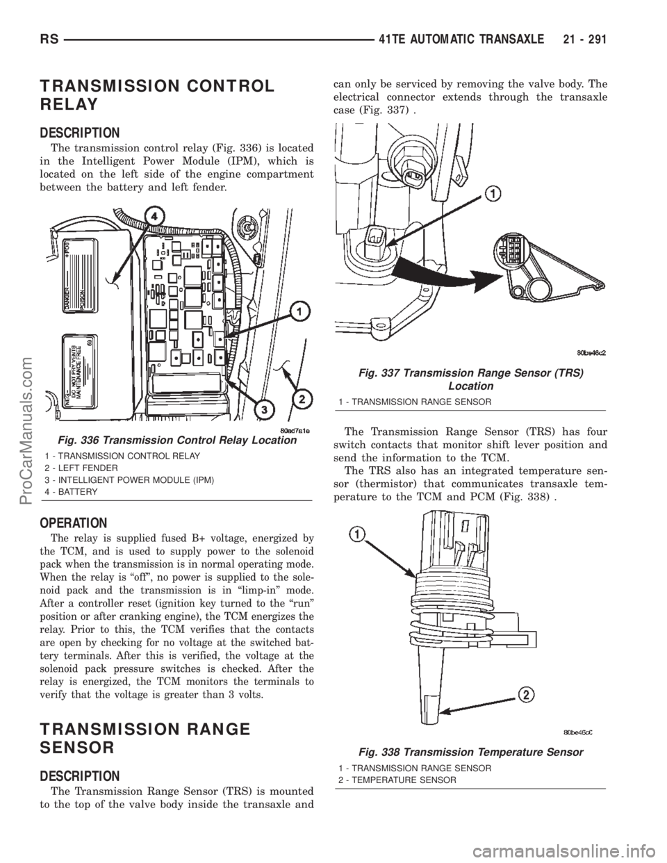
The transmission control relay (Fig. 336) is located
in the Intelligent Power Module (IPM), which is
located on the left side of the engine compartment
between the battery and left fender.
OPERATION
The relay is supplied fused B+ voltage, energized by
the TCM, and is used to supply power to the solenoid
pack when the transmission is in normal operating mode.
When the relay is ªoffº, no power is supplied to the sole-
noid pack and the transmission is in ªlimp-inº mode.
After a controller reset (ignition key turned to the ªrunº
position or after cranking engine), the TCM energizes the
relay. Prior to this, the TCM verifies that the contacts
are open by checking for no voltage at the switched bat-
tery terminals. After this is verified, the voltage at the
solenoid pack pressure switches is checked. After the
relay is energized, the TCM monitors the terminals to
verify that the voltage is greater than 3 volts.
TRANSMISSION RANGE
SENSOR
DESCRIPTION
The Transmission Range Sensor (TRS) is mounted
to the top of the valve body inside the transaxle andcan only be serviced by removing the valve body. The
electrical connector extends through the transaxle
case (Fig. 337) .
The Transmission Range Sensor (TRS) has four
switch contacts that monitor shift lever position and
send the information to the TCM.
The TRS also has an integrated temperature sen-
sor (thermistor) that communicates transaxle tem-
perature to the TCM and PCM (Fig. 338) .
Fig. 336 Transmission Control Relay Location
1 - TRANSMISSION CONTROL RELAY
2 - LEFT FENDER
3 - INTELLIGENT POWER MODULE (IPM)
4 - BATTERY
Fig. 337 Transmission Range Sensor (TRS)
Location
1 - TRANSMISSION RANGE SENSOR
Fig. 338 Transmission Temperature Sensor
1 - TRANSMISSION RANGE SENSOR
2 - TEMPERATURE SENSOR
RS41TE AUTOMATIC TRANSAXLE21 - 291
ProCarManuals.com
Page 1849 of 2399
OPERATION
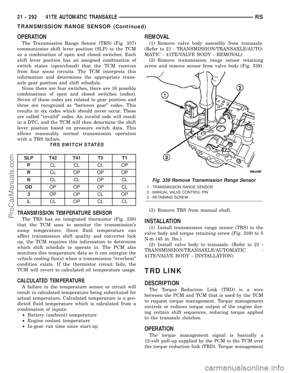
The Transmission Range Sensor (TRS) (Fig. 337)
communicates shift lever position (SLP) to the TCM
as a combination of open and closed switches. Each
shift lever position has an assigned combination of
switch states (open/closed) that the TCM receives
from four sense circuits. The TCM interprets this
information and determines the appropriate trans-
axle gear position and shift schedule.
Since there are four switches, there are 16 possible
combinations of open and closed switches (codes).
Seven of these codes are related to gear position and
three are recognized as ªbetween gearº codes. This
results in six codes which should never occur. These
are called ªinvalidº codes. An invalid code will result
in a DTC, and the TCM will then determine the shift
lever position based on pressure switch data. This
allows reasonably normal transmission operation
with a TRS failure.
TRS SWITCH STATES
SLP T42 T41 T3 T1
PCL CL CL OP
RCL OP OP OP
NCL CL OP CL
ODOP OP OP CL
3OP OP CL OP
LCL OP CL CL
TRANSMISSION TEMPERATURE SENSOR
The TRS has an integrated thermistor (Fig. 338)
that the TCM uses to monitor the transmission's
sump temperature. Since fluid temperature can
affect transmission shift quality and convertor lock
up, the TCM requires this information to determine
which shift schedule to operate in. The PCM also
monitors this temperature data so it can energize the
vehicle cooling fan(s) when a transmission ªoverheatº
condition exists. If the thermistor circuit fails, the
TCM will revert to calculated oil temperature usage.
CALCULATED TEMPERATURE
A failure in the temperature sensor or circuit will
result in calculated temperature being substituted for
actual temperature. Calculated temperature is a pre-
dicted fluid temperature which is calculated from a
combination of inputs:
²Battery (ambient) temperature
²Engine coolant temperature
²In-gear run time since start-up
REMOVAL
(1) Remove valve body assembly from transaxle.
(Refer to 21 - TRANSMISSION/TRANSAXLE/AUTO-
MATIC - 41TE/VALVE BODY - REMOVAL)
(2) Remove transmission range sensor retaining
screw and remove sensor from valve body (Fig. 339).
(3) Remove TRS from manual shaft.
INSTALLATION
(1) Install transmission range sensor (TRS) to the
valve body and torque retaining screw (Fig. 339) to 5
N´m (45 in. lbs.).
(2) Install valve body to transaxle. (Refer to 21 -
TRANSMISSION/TRANSAXLE/AUTOMATIC -
41TE/VALVE BODY - INSTALLATION)
TRD LINK
DESCRIPTION
The Torque Reduction Link (TRD) is a wire
between the PCM and TCM that is used by the TCM
to request torque management. Torque management
controls or reduces torque output of the engine dur-
ing certain shift sequences, reducing torque applied
to the transaxle clutches.
OPERATION
The torque management signal is basically a
12-volt pull-up supplied by the PCM to the TCM over
the torque reduction link (TRD). Torque management
Fig. 339 Remove Transmission Range Sensor
1 - TRANSMISSION RANGE SENSOR
2 - MANUAL VALVE CONTROL PIN
3 - RETAINING SCREW
21 - 292 41TE AUTOMATIC TRANSAXLERS
TRANSMISSION RANGE SENSOR (Continued)
ProCarManuals.com