fuel CHRYSLER VOYAGER 2002 Owner's Guide
[x] Cancel search | Manufacturer: CHRYSLER, Model Year: 2002, Model line: VOYAGER, Model: CHRYSLER VOYAGER 2002Pages: 2399, PDF Size: 57.96 MB
Page 372 of 2399
ELECTRONIC CONTROL MODULES
TABLE OF CONTENTS
page page
ENGINE CONTROL MODULE
DESCRIPTION..........................1
OPERATION............................1
STANDARD PROCEDURE - PCM/ECM/SKIM
PROGRAMMING - DIESEL...............2REMOVAL.............................4
INSTALLATION..........................4
ENGINE CONTROL MODULE
DESCRIPTION
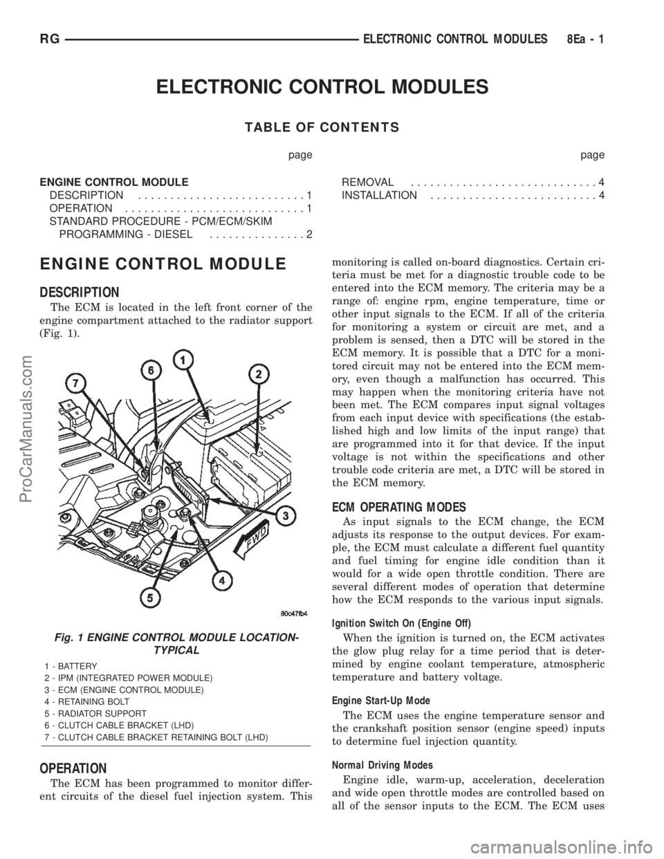
The ECM is located in the left front corner of the
engine compartment attached to the radiator support
(Fig. 1).
OPERATION
The ECM has been programmed to monitor differ-
ent circuits of the diesel fuel injection system. Thismonitoring is called on-board diagnostics. Certain cri-
teria must be met for a diagnostic trouble code to be
entered into the ECM memory. The criteria may be a
range of: engine rpm, engine temperature, time or
other input signals to the ECM. If all of the criteria
for monitoring a system or circuit are met, and a
problem is sensed, then a DTC will be stored in the
ECM memory. It is possible that a DTC for a moni-
tored circuit may not be entered into the ECM mem-
ory, even though a malfunction has occurred. This
may happen when the monitoring criteria have not
been met. The ECM compares input signal voltages
from each input device with specifications (the estab-
lished high and low limits of the input range) that
are programmed into it for that device. If the input
voltage is not within the specifications and other
trouble code criteria are met, a DTC will be stored in
the ECM memory.
ECM OPERATING MODES
As input signals to the ECM change, the ECM
adjusts its response to the output devices. For exam-
ple, the ECM must calculate a different fuel quantity
and fuel timing for engine idle condition than it
would for a wide open throttle condition. There are
several different modes of operation that determine
how the ECM responds to the various input signals.
Ignition Switch On (Engine Off)
When the ignition is turned on, the ECM activates
the glow plug relay for a time period that is deter-
mined by engine coolant temperature, atmospheric
temperature and battery voltage.
Engine Start-Up Mode
The ECM uses the engine temperature sensor and
the crankshaft position sensor (engine speed) inputs
to determine fuel injection quantity.
Normal Driving Modes
Engine idle, warm-up, acceleration, deceleration
and wide open throttle modes are controlled based on
all of the sensor inputs to the ECM. The ECM uses
Fig. 1 ENGINE CONTROL MODULE LOCATION-
TYPICAL
1 - BATTERY
2 - IPM (INTEGRATED POWER MODULE)
3 - ECM (ENGINE CONTROL MODULE)
4 - RETAINING BOLT
5 - RADIATOR SUPPORT
6 - CLUTCH CABLE BRACKET (LHD)
7 - CLUTCH CABLE BRACKET RETAINING BOLT (LHD)
RGELECTRONIC CONTROL MODULES8Ea-1
ProCarManuals.com
Page 373 of 2399
these sensor inputs to adjust fuel quantity and fuel
injector timing.
Limp-In Mode
If there is a fault detected with the accelerator
pedal position sensor, the ECM will set the engine
speed at 1100 RPM.
Overspeed Detection Mode
If the ECM detects engine RPM that exceeds 5200
RPM, the ECM will set a DTC in memory and illu-
minate the MIL until the DTC is cleared.
After-Run Mode
The ECM transfers RAM information to ROM and
performs an Input/Output state check.
MONITORED CIRCUITS
The ECM is able to monitor and identify most
driveability related trouble conditions. Some circuits
are directly monitored through ECM feedback cir-
cuitry. In addition, the ECM monitors the voltage
state of some circuits and compares those states with
expected values. Other systems are monitored indi-
rectly when the ECM conducts a rationality test to
identify problems. Although most subsytems of the
engine control module are either directly or indirectly
monitored, there may be occasions when diagnostic
trouble codes are not immediately identified. For a
trouble code to set, a specific set of conditions must
occur and unless these conditions occur, a DTC will
not set.
DIAGNOSTIC TROUBLE CODES
Each diagnostic trouble code (DTC) is diagnosed by
following a specific procedure. The diagnostic test
procedure contains step-by-step instruction for deter-
mining the cause of the DTC as well as no trouble
code problems. Refer to the appropriate Diesel Pow-
ertrain Diagnostic Manual for more information.
HARD CODE
A DTC that comes back within one cycle of the
ignition key is a hard code. This means that the
problem is current every time the ECM/SKIM checks
that circuit or function. Procedures in this manual
verify if the DTC is a hard code at the beginning of
each test. When the fault is not a hard code, an
intermittent test must be performed. NOTE: If the
DRBIIItdisplays faults for multiple components (i.e.
ECT, VSS, IAT sensors) identify and check the
shared circuits for possible problems before continu-
ing (i.e. sensor grounds or 5-volt supply circuits).
Refer to the appropriate schematic to identify shared
circuits. Refer to the appropriate Diesel Powertrain
Diagnostic Manual for more information.INTERMITTENT CODE
A DTC that is not current every time the ECM/
SKIM checks the circuit or function is an intermit-
tent code. Most intermittent DTCs are caused by
wiring or connector problems. Problems that come
and go like this are the most difficult to diagnose;
they must be looked for under specific conditions that
cause them.NOTE: Electromagnetic (radio)
interference can cause an intermittent system
malfunction.This interference can interrupt com-
munication between the ignition key transponder and
the SKIM. The following checks may assist you in
identifying a possible intermittent problem:
²Visually inspect the related wire harness connec-
tors. Look for broken, bent, pushed out or corroded
terminals.
²Visually inspect the related wire harness. Look
for chafed, pierced or partially broken wire.
²Refer to hotlines or technical service bulletins
that may apply. Refer to the appropriate Diesel Pow-
ertrain Diagnostic Manual for more information.
ECM DIAGNOSTIC TROUBLE CODES
IMPORTANT NOTE: Before replacing the ECM for
a failed driver, control circuit or ground circuit, be
sure to check the related component/circuit integrity
for failures not detected due to a double fault in the
circuit. Most ECM driver/control circuit failures are
caused by internal failures to components (i.e. relays
and solenoids) and shorted circuits (i.e. sensor pull-
ups, drivers and ground circuits). These faults are
difficult to detect when a double fault has occurred
and only one DTC has set. If the DRBIIItdisplays
faults for multiple components (i.e.VSS, ECT, Batt
Temp, etc.) identify and check the shared circuits for
possible problems before continuing (i.e. sensor
grounds or 5-volt supply circuits). Refer to the appro-
priate wiring diagrams to identify shared circuits.
Refer to the appropriate Diesel Powertrain Diagnos-
tic Manual for more information.
STANDARD PROCEDURE - PCM/ECM/SKIM
PROGRAMMING - DIESEL
NOTE: Before replacing the PCM/ECM for a failed
driver, control circuit or ground circuit, be sure to
check the related component/circuit integrity for
failures not detected due to a double fault in the cir-
cuit. Most PCM/ECM driver/control circuit failures
are caused by internal component failures (i.e. relay
and solenoids) and shorted circuits (i.e. pull-ups,
drivers and switched circuits). These failures are
difficult to detect when a double fault has occurred
and only one DTC has set.
8Ea - 2 ELECTRONIC CONTROL MODULESRG
ENGINE CONTROL MODULE (Continued)
ProCarManuals.com
Page 406 of 2399
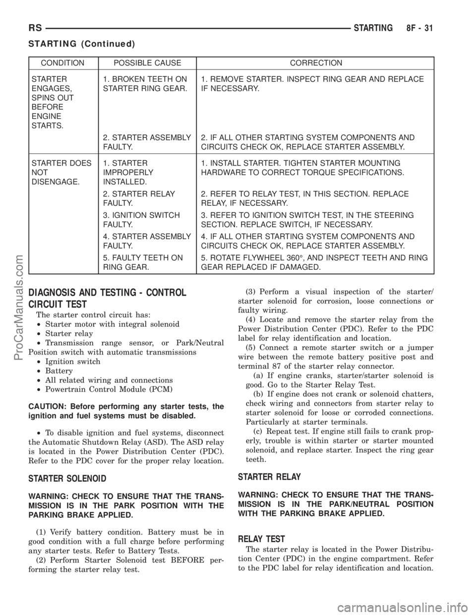
CONDITION POSSIBLE CAUSE CORRECTION
STARTER
ENGAGES,
SPINS OUT
BEFORE
ENGINE
STARTS.1. BROKEN TEETH ON
STARTER RING GEAR.1. REMOVE STARTER. INSPECT RING GEAR AND REPLACE
IF NECESSARY.
2. STARTER ASSEMBLY
FAULTY.2. IF ALL OTHER STARTING SYSTEM COMPONENTS AND
CIRCUITS CHECK OK, REPLACE STARTER ASSEMBLY.
STARTER DOES
NOT
DISENGAGE.1. STARTER
IMPROPERLY
INSTALLED.1. INSTALL STARTER. TIGHTEN STARTER MOUNTING
HARDWARE TO CORRECT TORQUE SPECIFICATIONS.
2. STARTER RELAY
FAULTY.2. REFER TO RELAY TEST, IN THIS SECTION. REPLACE
RELAY, IF NECESSARY.
3. IGNITION SWITCH
FAULTY.3. REFER TO IGNITION SWITCH TEST, IN THE STEERING
SECTION. REPLACE SWITCH, IF NECESSARY.
4. STARTER ASSEMBLY
FAULTY.4. IF ALL OTHER STARTING SYSTEM COMPONENTS AND
CIRCUITS CHECK OK, REPLACE STARTER ASSEMBLY.
5. FAULTY TEETH ON
RING GEAR.5. ROTATE FLYWHEEL 360É, AND INSPECT TEETH AND RING
GEAR REPLACED IF DAMAGED.
DIAGNOSIS AND TESTING - CONTROL
CIRCUIT TEST
The starter control circuit has:
²Starter motor with integral solenoid
²Starter relay
²Transmission range sensor, or Park/Neutral
Position switch with automatic transmissions
²Ignition switch
²Battery
²All related wiring and connections
²Powertrain Control Module (PCM)
CAUTION: Before performing any starter tests, the
ignition and fuel systems must be disabled.
²To disable ignition and fuel systems, disconnect
the Automatic Shutdown Relay (ASD). The ASD relay
is located in the Power Distribution Center (PDC).
Refer to the PDC cover for the proper relay location.
STARTER SOLENOID
WARNING: CHECK TO ENSURE THAT THE TRANS-
MISSION IS IN THE PARK POSITION WITH THE
PARKING BRAKE APPLIED.
(1) Verify battery condition. Battery must be in
good condition with a full charge before performing
any starter tests. Refer to Battery Tests.
(2) Perform Starter Solenoid test BEFORE per-
forming the starter relay test.(3) Perform a visual inspection of the starter/
starter solenoid for corrosion, loose connections or
faulty wiring.
(4) Locate and remove the starter relay from the
Power Distribution Center (PDC). Refer to the PDC
label for relay identification and location.
(5) Connect a remote starter switch or a jumper
wire between the remote battery positive post and
terminal 87 of the starter relay connector.
(a) If engine cranks, starter/starter solenoid is
good. Go to the Starter Relay Test.
(b) If engine does not crank or solenoid chatters,
check wiring and connectors from starter relay to
starter solenoid for loose or corroded connections.
Particularly at starter terminals.
(c) Repeat test. If engine still fails to crank prop-
erly, trouble is within starter or starter mounted
solenoid, and replace starter. Inspect the ring gear
teeth.
STARTER RELAY
WARNING: CHECK TO ENSURE THAT THE TRANS-
MISSION IS IN THE PARK/NEUTRAL POSITION
WITH THE PARKING BRAKE APPLIED.
RELAY TEST
The starter relay is located in the Power Distribu-
tion Center (PDC) in the engine compartment. Refer
to the PDC label for relay identification and location.
RSSTARTING8F-31
STARTING (Continued)
ProCarManuals.com
Page 408 of 2399

tion. If that checks OK check for continuity between
PCM and the terminal 85. Repair open circuit as
required. If OK, the PCM may be defective.
SAFETY SWITCHES
For diagnostics of the Transmission Range Sensor,
refer to the Transaxle section for more information.
If equipped with Clutch Interlock/Upstop Switch,
refer to Diagnosis and Testing in the Clutch section.
IGNITION SWITCH
After testing starter solenoid and relay, test igni-
tion switch and wiring. Refer to the Ignition Section
or Wiring Diagrams for more information. Check all
wiring for opens or shorts, and all connectors for
being loose or corroded.
BATTERY
For battery diagnosis and testing, refer to the Bat-
tery section for procedures.
ALL RELATED WIRING AND CONNECTORS
Refer to Wiring Diagrams for more information.
DIAGNOSIS AND TESTING - FEED CIRCUIT
RESISTANCE TEST
Before proceeding with this operation, review Diag-
nostic Preparation and Starter Feed Circuit Tests.
The following operation will require a voltmeter,
accurate to 1/10 of a volt.
CAUTION: Ignition and Fuel systems must be dis-
abled to prevent engine start while performing the
following tests.
(1) To disable the Ignition and Fuel systems, dis-
connect the Automatic Shutdown Relay (ASD). The
ASD relay is located in the Power Distribution Cen-
ter (PDC). Refer to the PDC cover for proper relay
location.
(2) Gain access to battery terminals.
(3) With all wiring harnesses and components
properly connected, perform the following:
(a) Connect the negative lead of the voltmeter to
the battery negative post, and positive lead to the
battery negative cable clamp. Rotate and hold the
ignition switch in the START position. Observe the
voltmeter. If voltage is detected, correct poor con-
tact between cable clamp and post.
(b) Connect positive lead of the voltmeter to the
battery positive post, and negative lead to the bat-
tery positive cable clamp. Rotate and hold the igni-
tion switch key in the START position. Observe the
voltmeter. If voltage is detected, correct poor con-
tact between the cable clamp and post.(c) Connect negative lead of voltmeter to battery
negative terminal, and positive lead to engine
block near the battery cable attaching point.
Rotate and hold the ignition switch in the START
position. If voltage reads above 0.2 volt, correct
poor contact at ground cable attaching point. If
voltage reading is still above 0.2 volt after correct-
ing poor contacts, replace ground cable.
(4) Connect positive voltmeter lead to the starter
motor housing and the negative lead to the battery
negative terminal. Hold the ignition switch key in
the START position. If voltage reads above 0.2 volt,
correct poor starter to engine ground.
(a) Connect the positive voltmeter lead to the
battery positive terminal, and negative lead to bat-
tery cable terminal on starter solenoid. Rotate and
hold the ignition switch in the START position. If
voltage reads above 0.2 volt, correct poor contact at
battery cable to solenoid connection. If reading is
still above 0.2 volt after correcting poor contacts,
replace battery positive cable.
(b) If resistance tests do not detect feed circuit
failures, replace the starter motor.
DIAGNOSIS AND TESTING - FEED CIRCUIT
TEST
NOTE: The following results are based upon the
vehicle being at room temperature.
The following procedure will require a suitable
volt-ampere tester (Fig. 3).
CAUTION: Before performing any starter tests, the
ignition and fuel systems must be disabled.
(1) Check battery before performing this test. Bat-
tery must be fully charged.
(2) Connect a volt-ampere tester to the battery ter-
minals. Refer to the operating instructions provided
with the tester being used.
Fig. 3 Volt Ampere Tester
RSSTARTING8F-33
STARTING (Continued)
ProCarManuals.com
Page 409 of 2399
(3) To disable the ignition and fuel systems, dis-
connect the Automatic Shutdown Relay (ASD). The
ASD relay is located in the Power Distribution Cen-
ter (PDC). Refer to the PDC cover for proper relay
location.
(4) Verify that all lights and accessories are OFF,
and the transmission shift selector is in the PARK
and SET parking brake.
CAUTION: Do not overheat the starter motor or
draw the battery voltage below 9.6 volts during
cranking operations.
(5) Rotate and hold the ignition switch in the
START position. Observe the volt-ampere tester (Fig.
3).
²If voltage reads above 9.6 volts, and amperage
draw reads above 280 amps, check for engine seizing
or faulty starter.
²If voltage reads 12.4 volts or greater and amper-
age reads 0 to 10 amps, check for corroded cables
and/or bad connections.
²Voltage below 9.6 volts and amperage draw
above 300 amps, the problem is the starter. Replace
the starter refer to starter removal.
(6) After the starting system problems have been
corrected, verify the battery state-of-charge and
charge battery if necessary. Disconnect all testing
equipment and connect ASD relay. Start the vehicle
several times to assure the problem has been cor-
rected.SPECIFICATIONS
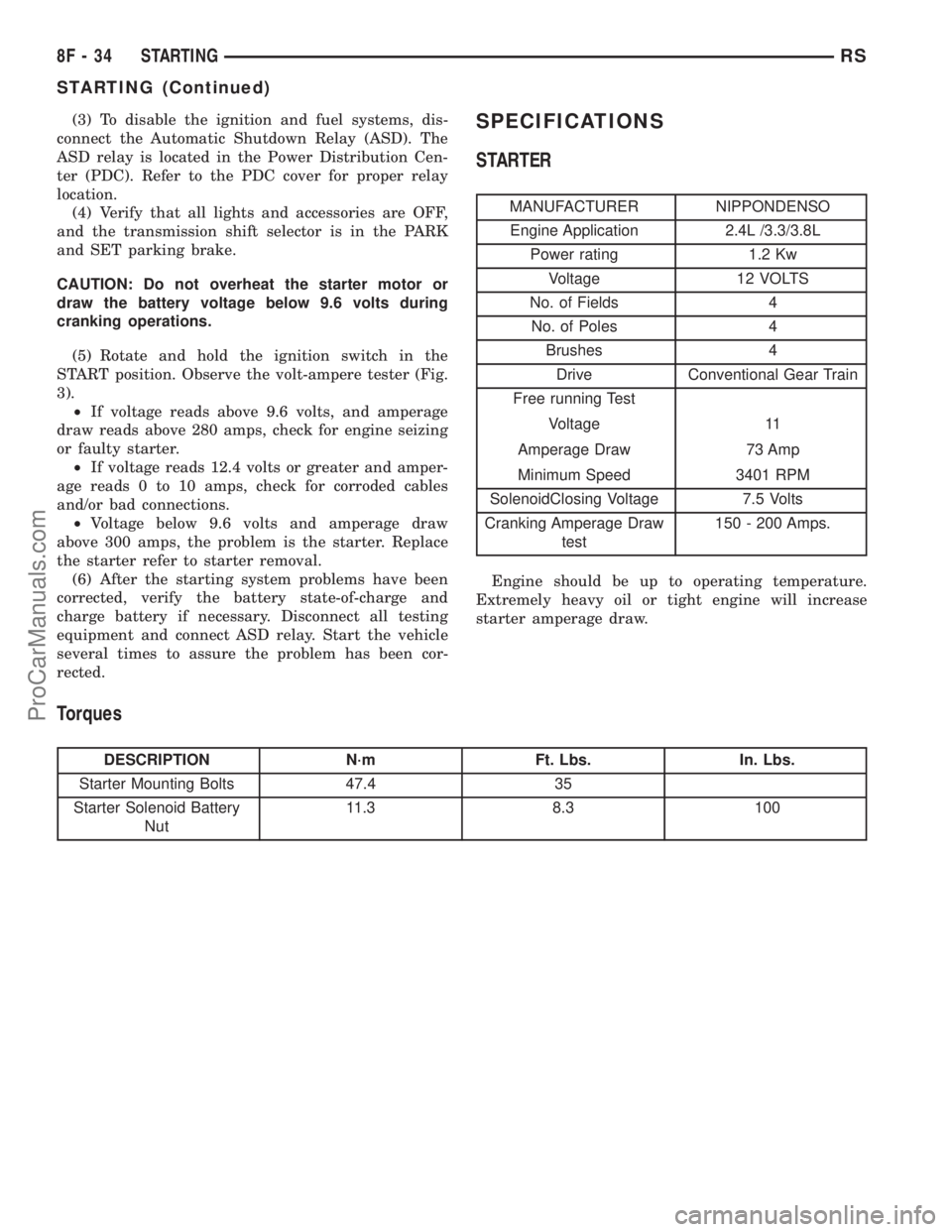
STARTER
MANUFACTURER NIPPONDENSO
Engine Application 2.4L /3.3/3.8L
Power rating 1.2 Kw
Voltage 12 VOLTS
No. of Fields 4
No. of Poles 4
Brushes 4
Drive Conventional Gear Train
Free running Test
Voltage 11
Amperage Draw 73 Amp
Minimum Speed 3401 RPM
SolenoidClosing Voltage 7.5 Volts
Cranking Amperage Draw
test150 - 200 Amps.
Engine should be up to operating temperature.
Extremely heavy oil or tight engine will increase
starter amperage draw.
Torques
DESCRIPTION N´m Ft. Lbs. In. Lbs.
Starter Mounting Bolts 47.4 35
Starter Solenoid Battery
Nut11.3 8.3 100
8F - 34 STARTINGRS
STARTING (Continued)
ProCarManuals.com
Page 445 of 2399
CONDITION POSSIBLE CAUSE CORRECTION
STARTER
ENGAGES,
SPINS OUT
BEFORE
ENGINE
STARTS.1. BROKEN TEETH ON
STARTER RING GEAR.1. REMOVE STARTER. INSPECT RING GEAR AND REPLACE
IF NECESSARY.
2. STARTER ASSEMBLY
FAULTY.2. IF ALL OTHER STARTING SYSTEM COMPONENTS AND
CIRCUITS CHECK OK, REPLACE STARTER ASSEMBLY.
STARTER DOES
NOT
DISENGAGE.1. STARTER
IMPROPERLY
INSTALLED.1. INSTALL STARTER. TIGHTEN STARTER MOUNTING
HARDWARE TO CORRECT TORQUE SPECIFICATIONS.
2. STARTER RELAY
FAULTY.2. REFER TO RELAY TEST, IN THIS SECTION. REPLACE
RELAY, IF NECESSARY.
3. IGNITION SWITCH
FAULTY.3. REFER TO IGNITION SWITCH TEST, IN THE STEERING
SECTION. REPLACE SWITCH, IF NECESSARY.
4. STARTER ASSEMBLY
FAULTY.4. IF ALL OTHER STARTING SYSTEM COMPONENTS AND
CIRCUITS CHECK OK, REPLACE STARTER ASSEMBLY.
5. FAULTY TEETH ON
RING GEAR.5. ROTATE FLYWHEEL 360É, AND INSPECT TEETH AND RING
GEAR REPLACED IF DAMAGED.
DIAGNOSIS AND TESTING - CONTROL
CIRCUIT TEST
The starter control circuit has:
²Starter motor with integral solenoid
²Starter relay
²Transmission range sensor, or Park/Neutral
Position switch with automatic transmissions
²Ignition switch
²Battery
²All related wiring and connections
²Powertrain Control Module (PCM)
CAUTION: Before performing any starter tests, the
ignition and fuel systems must be disabled.
²To disable ignition and fuel systems, disconnect
the Automatic Shutdown Relay (ASD). The ASD relay
is located in the Power Distribution Center (PDC).
Refer to the PDC cover for the proper relay location.
STARTER SOLENOID
WARNING: CHECK TO ENSURE THAT THE TRANS-
MISSION IS IN THE PARK POSITION WITH THE
PARKING BRAKE APPLIED.
(1) Verify battery condition. Battery must be in
good condition with a full charge before performing
any starter tests. Refer to Battery Tests.
(2) Perform Starter Solenoid test BEFORE per-
forming the starter relay test.(3) Perform a visual inspection of the starter/
starter solenoid for corrosion, loose connections or
faulty wiring.
(4) Locate and remove the starter relay from the
Power Distribution Center (PDC). Refer to the PDC
label for relay identification and location.
(5) Connect a remote starter switch or a jumper
wire between the remote battery positive post and
terminal 87 of the starter relay connector.
(a) If engine cranks, starter/starter solenoid is
good. Go to the Starter Relay Test.
(b) If engine does not crank or solenoid chatters,
check wiring and connectors from starter relay to
starter solenoid for loose or corroded connections.
Particularly at starter terminals.
(c) Repeat test. If engine still fails to crank prop-
erly, trouble is within starter or starter mounted
solenoid, and replace starter. Inspect the ring gear
teeth.
STARTER RELAY
WARNING: CHECK TO ENSURE THAT THE TRANS-
MISSION IS IN THE PARK/NEUTRAL POSITION
WITH THE PARKING BRAKE APPLIED.
RELAY TEST
The starter relay is located in the Power Distribu-
tion Center (PDC) in the engine compartment. Refer
to the PDC label for relay identification and location.
8Fa - 34 STARTINGRG
STARTING (Continued)
ProCarManuals.com
Page 447 of 2399
tion. If that checks OK check for continuity between
PCM and the terminal 85. Repair open circuit as
required. If OK, the PCM may be defective.
SAFETY SWITCHES
For diagnostics of the Transmission Range Sensor,
refer to the Transaxle section for more information.
If equipped with Clutch Interlock/Upstop Switch,
refer to Diagnosis and Testing in the Clutch section.
IGNITION SWITCH
After testing starter solenoid and relay, test igni-
tion switch and wiring. Refer to the Ignition Section
or Wiring Diagrams for more information. Check all
wiring for opens or shorts, and all connectors for
being loose or corroded.
BATTERY
For battery diagnosis and testing, refer to the Bat-
tery section for procedures.
ALL RELATED WIRING AND CONNECTORS
Refer to Wiring Diagrams for more information.
DIAGNOSIS AND TESTING - FEED CIRCUIT
RESISTANCE TEST
Before proceeding with this operation, review Diag-
nostic Preparation and Starter Feed Circuit Tests.
The following operation will require a voltmeter,
accurate to 1/10 of a volt.
CAUTION: Ignition and Fuel systems must be dis-
abled to prevent engine start while performing the
following tests.
(1) To disable the Ignition and Fuel systems, dis-
connect the Automatic Shutdown Relay (ASD). The
ASD relay is located in the Power Distribution Cen-
ter (PDC). Refer to the PDC cover for proper relay
location.
(2) Gain access to battery terminals.
(3) With all wiring harnesses and components
properly connected, perform the following:
(a) Connect the negative lead of the voltmeter to
the battery negative post, and positive lead to the
battery negative cable clamp. Rotate and hold the
ignition switch in the START position. Observe the
voltmeter. If voltage is detected, correct poor con-
tact between cable clamp and post.
(b) Connect positive lead of the voltmeter to the
battery positive post, and negative lead to the bat-
tery positive cable clamp. Rotate and hold the igni-
tion switch key in the START position. Observe the
voltmeter. If voltage is detected, correct poor con-
tact between the cable clamp and post.(c) Connect negative lead of voltmeter to battery
negative terminal, and positive lead to engine
block near the battery cable attaching point.
Rotate and hold the ignition switch in the START
position. If voltage reads above 0.2 volt, correct
poor contact at ground cable attaching point. If
voltage reading is still above 0.2 volt after correct-
ing poor contacts, replace ground cable.
(4) Connect positive voltmeter lead to the starter
motor housing and the negative lead to the battery
negative terminal. Hold the ignition switch key in
the START position. If voltage reads above 0.2 volt,
correct poor starter to engine ground.
(a) Connect the positive voltmeter lead to the
battery positive terminal, and negative lead to bat-
tery cable terminal on starter solenoid. Rotate and
hold the ignition switch in the START position. If
voltage reads above 0.2 volt, correct poor contact at
battery cable to solenoid connection. If reading is
still above 0.2 volt after correcting poor contacts,
replace battery positive cable.
(b) If resistance tests do not detect feed circuit
failures, replace the starter motor.
DIAGNOSIS AND TESTING - FEED CIRCUIT
TEST
NOTE: The following results are based upon the
vehicle being at room temperature.
The following procedure will require a suitable
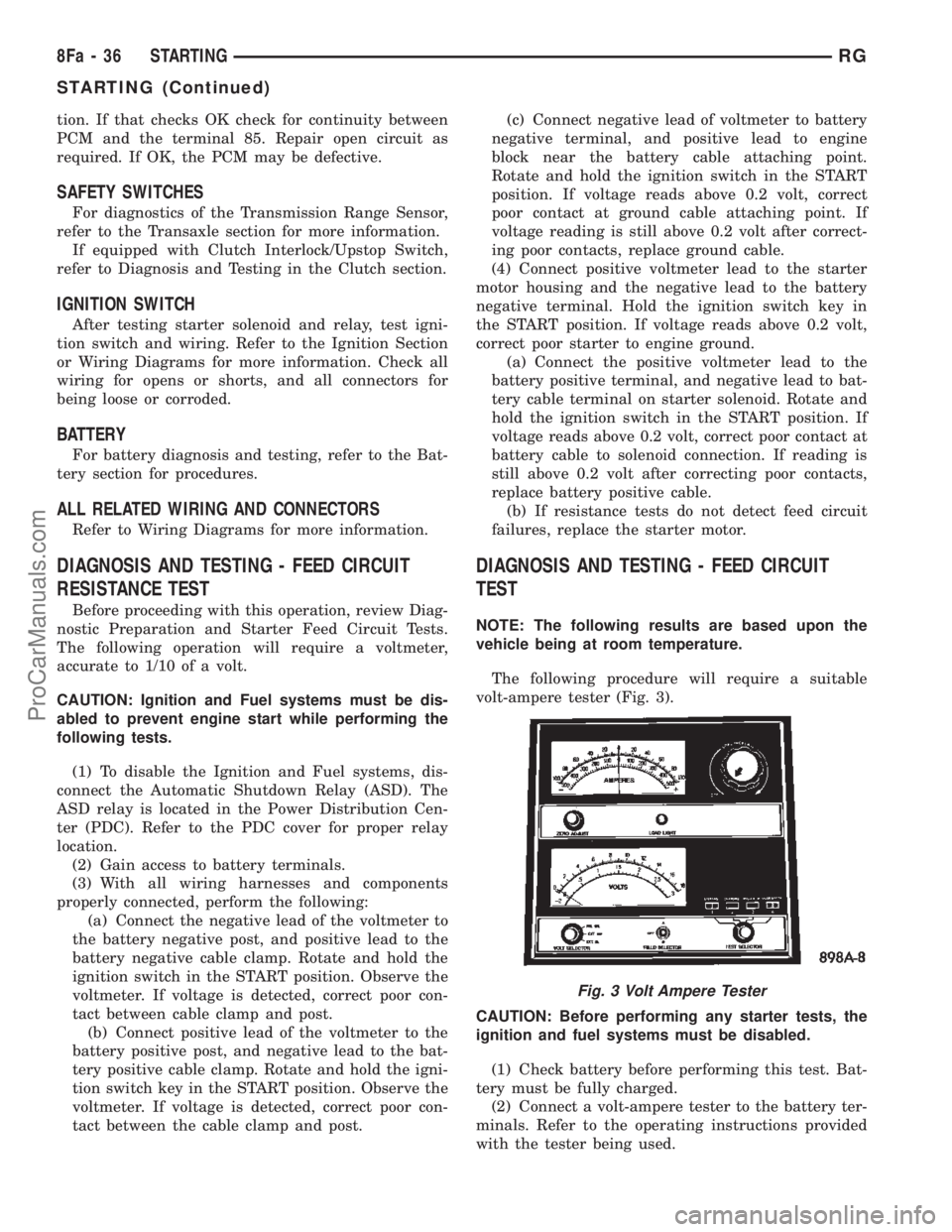
volt-ampere tester (Fig. 3).
CAUTION: Before performing any starter tests, the
ignition and fuel systems must be disabled.
(1) Check battery before performing this test. Bat-
tery must be fully charged.
(2) Connect a volt-ampere tester to the battery ter-
minals. Refer to the operating instructions provided
with the tester being used.
Fig. 3 Volt Ampere Tester
8Fa - 36 STARTINGRG
STARTING (Continued)
ProCarManuals.com
Page 448 of 2399
(3) To disable the ignition and fuel systems, dis-
connect the Automatic Shutdown Relay (ASD). The
ASD relay is located in the Power Distribution Cen-
ter (PDC). Refer to the PDC cover for proper relay
location.
(4) Verify that all lights and accessories are OFF,
and the transmission shift selector is in the PARK
and SET parking brake.
CAUTION: Do not overheat the starter motor or
draw the battery voltage below 9.6 volts during
cranking operations.
(5) Rotate and hold the ignition switch in the
START position. Observe the volt-ampere tester (Fig.
3).
²If voltage reads above 9.6 volts, and amperage
draw reads above 280 amps, check for engine seizing
or faulty starter.
²If voltage reads 12.4 volts or greater and amper-
age reads 0 to 10 amps, check for corroded cables
and/or bad connections.
²Voltage below 9.6 volts and amperage draw
above 300 amps, the problem is the starter. Replace
the starter refer to starter removal.
(6) After the starting system problems have been
corrected, verify the battery state-of-charge and
charge battery if necessary. Disconnect all testing
equipment and connect ASD relay. Start the vehicle
several times to assure the problem has been cor-
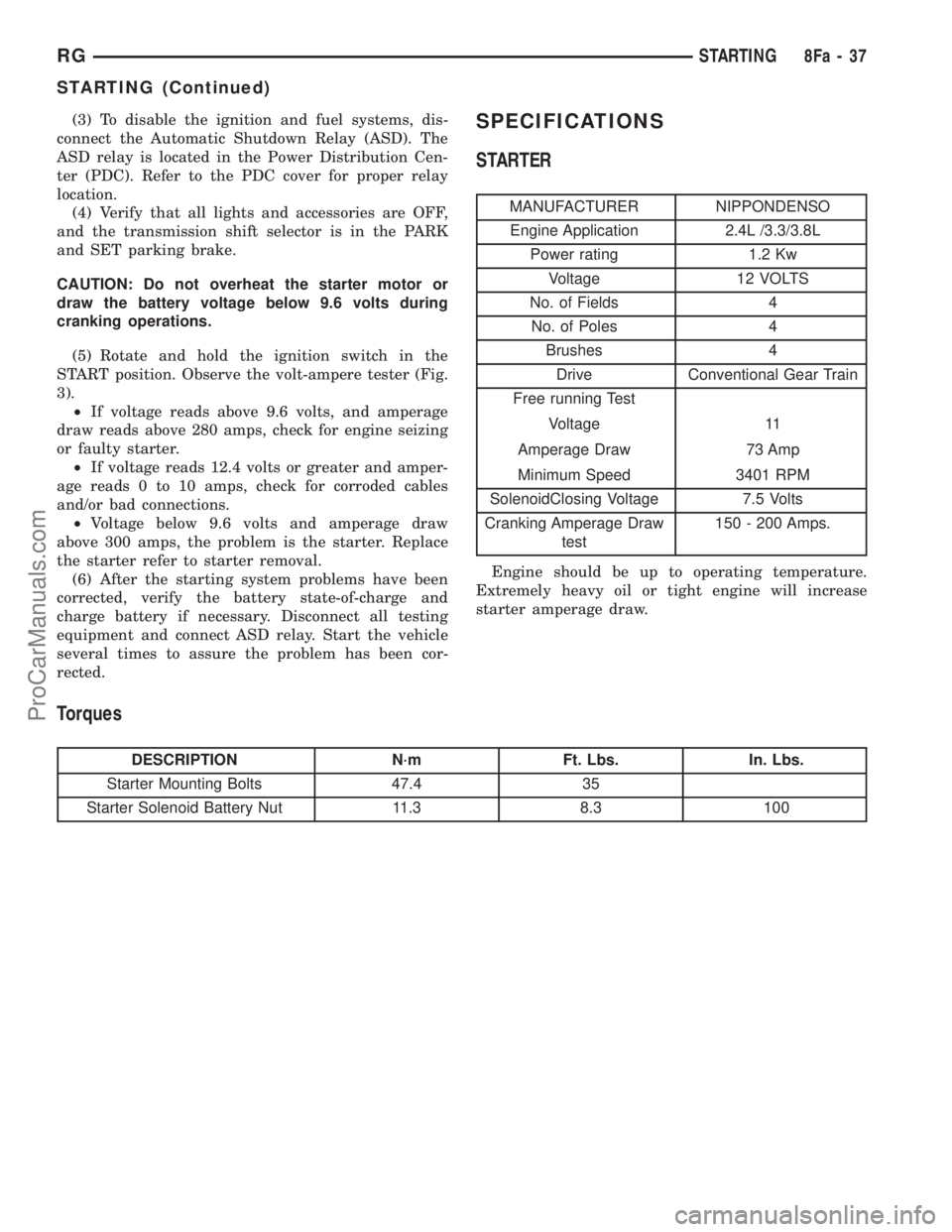
rected.SPECIFICATIONS
STARTER
MANUFACTURER NIPPONDENSO
Engine Application 2.4L /3.3/3.8L
Power rating 1.2 Kw
Voltage 12 VOLTS
No. of Fields 4
No. of Poles 4
Brushes 4
Drive Conventional Gear Train
Free running Test
Voltage 11
Amperage Draw 73 Amp
Minimum Speed 3401 RPM
SolenoidClosing Voltage 7.5 Volts
Cranking Amperage Draw
test150 - 200 Amps.
Engine should be up to operating temperature.
Extremely heavy oil or tight engine will increase
starter amperage draw.
Torques
DESCRIPTION N´m Ft. Lbs. In. Lbs.
Starter Mounting Bolts 47.4 35
Starter Solenoid Battery Nut 11.3 8.3 100
RGSTARTING8Fa-37
STARTING (Continued)
ProCarManuals.com
Page 478 of 2399

FIRING ORDERAUTO SHUT DOWN RELAY
DESCRIPTION
The relay is located in the Power Distribution Cen-
ter (PDC). For the location of the relay within the
PDC, refer to the PDC cover for location. Check elec-
trical terminals for corrosion and repair as necessary
OPERATION
The ASD sense circuit informs the PCM when the
ASD relay energizes. A 12 volt signal at this input
indicates to the PCM that the ASD has been acti-
vated. This input is used only to sense that the ASD
relay is energized.
When energized, the ASD relay supplies battery
voltage to the fuel injectors, ignition coils and the
heating element in each oxygen sensor.
When energized, the ASD relay provides power to
operate the injectors, ignition coil, generator field, O2
sensor heaters (both upstream and downstream),
(EGR solenoid and PCV heater if equipped) and also
provides a sense circuit to the PCM for diagnostic
purposes. If the PCM does not receive 12 volts from
this input after grounding the ASD relay, it sets a
Diagnostic Trouble Code (DTC). The PCM energizes
the ASD any time there is a Crankshaft Position sen-
sor signal that exceeds a predetermined value. The
ASD relay can also be energized after the engine has
been turned off to perform an O2 sensor heater test,
if vehicle is equipped with OBD II diagnostics.
As mentioned earlier, the PCM energizes the ASD
relay during an O2 sensor heater test. This test is
performed only after the engine has been shut off.
The PCM still operates internally to perform several
checks, including monitoring the O2 sensor heaters.
CAMSHAFT POSITION
SENSOR
DESCRIPTION
The camshaft position sensorfor the 3.3/3.8L is
mounted in the front of the timing case cover (Fig. 6)
and the camshaft position sensor for the 2.4L is
mounted on the end of the cylinder head (Fig. 3).
FIRING ORDER 2.4L
Firing Order 1-2-3-4-5-6 3.3/3.8L
1 - Electrical Connector
RSIGNITION CONTROL8I-3
IGNITION CONTROL (Continued)
ProCarManuals.com
Page 487 of 2399

The Glow Plug lamp is tied to this circuit. Lamp
operation is also controlled by the ECM.
With a cold engine, the glow plug relays and glow
plugs may be activated for a maximum time of 200
seconds. Refer to the following Glow Plug Control
chart for a temperature/time comparison of the glow
plug relay operation.
In this chart, Pre-Heat and Post-Heat times are
mentioned. Pre-Heat is the amount of time the glow
plug relay control circuit is activated when the igni-
tion (key) is switched ON, without the engine run-
ning. Post-Heat is the amount of time the glow plug
relay control circuit is activated after the engine is
operated. The Glow Plug lamp will not be activated
during the post-heat cycle.
Engine
Coolant
Temperature
9Key ON9Wait-To
Start Lamp
9ON9
(Seconds)Pre-Heat
Cycle
(Glow
Plugs On
Seconds)Post-Heat
Cycle
(Seconds)
-30C 20 SEC. 35 SEC. 200 SEC.
-10C 8 SEC. 23 SEC. 180 SEC.
+10C 6 SEC. 21 SEC. 160 SEC.
+30C 5 SEC. 20 SEC. 140 SEC.
+40C 4 SEC. 19 SEC. 70 SEC.
+70C 1 SEC. 16 SEC. 20 SEC.
CAMSHAFT POSITION
SENSOR
DESCRIPTION
The camshaft position (CMP) sensor is mounted in
the top of cylinder head cover/intake manifold at the
rear of the engine. The CMP sensor is a hall effect
device (Fig. 3).
OPERATION
The CMP sensor is a hall effect switch. A tooth
made of a ferromagnetic material is attached to the
camshaft. When this tooth passes the CMP sensor an
lectronic signal is created. This signal is then sent to
the engine control module (ECM). This signal is used
by the ECM to determine which cylinder has just
entered its compression phase.
REMOVAL
(1) Disconnect negative battery cable.
(2) Remove engine cover (Refer to 9 - ENGINE
COVER - REMOVAL).
(3) Disconnect camshaft position sensor electrical
connector (Fig. 4).
(4) Remove sensor retaining bolt and remove sen-
sor from cylinder head cover.
INSTALLATION
(1) Lubricate O-ring and install sensor in cylinder
head cover. Torque retaining bolt to 5.4 N´m.
(2) Connect camshaft position sensor electrical
connector.
(3) Install engine cover (Refer to 9 - ENGINE
COVER - INSTALLATION).
(4) Connect negative battery cable.
Fig. 3 CAMSHAFT POSITION SENSOR
Fig. 4 CAMSHAFT POSITION SENSOR LOCATION
1 - CAMSHAFT POSITION SENSOR
2 - CAMSHAFT POSITION SENSOR ELCTRICAL SENSOR
3 - FUEL INJECTOR
4 - CYLINDER HEAD COVER
5 - OIL SEPARATOR
8Ia - 2 IGNITION CONTROLRG
GLOW PLUG RELAY (Continued)
ProCarManuals.com