sensor CHRYSLER VOYAGER 2002 Owner's Guide
[x] Cancel search | Manufacturer: CHRYSLER, Model Year: 2002, Model line: VOYAGER, Model: CHRYSLER VOYAGER 2002Pages: 2399, PDF Size: 57.96 MB
Page 221 of 2399
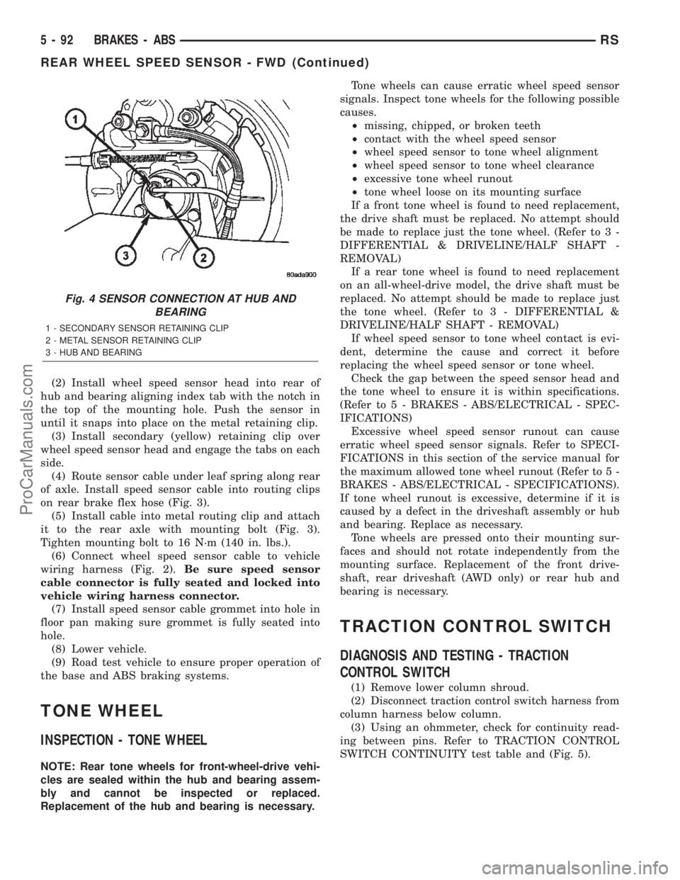
(2) Install wheel speed sensor head into rear of
hub and bearing aligning index tab with the notch in
the top of the mounting hole. Push the sensor in
until it snaps into place on the metal retaining clip.
(3) Install secondary (yellow) retaining clip over
wheel speed sensor head and engage the tabs on each
side.
(4) Route sensor cable under leaf spring along rear
of axle. Install speed sensor cable into routing clips
on rear brake flex hose (Fig. 3).
(5) Install cable into metal routing clip and attach
it to the rear axle with mounting bolt (Fig. 3).
Tighten mounting bolt to 16 N´m (140 in. lbs.).
(6) Connect wheel speed sensor cable to vehicle
wiring harness (Fig. 2).Be sure speed sensor
cable connector is fully seated and locked into
vehicle wiring harness connector.
(7) Install speed sensor cable grommet into hole in
floor pan making sure grommet is fully seated into
hole.
(8) Lower vehicle.
(9) Road test vehicle to ensure proper operation of
the base and ABS braking systems.
TONE WHEEL
INSPECTION - TONE WHEEL
NOTE: Rear tone wheels for front-wheel-drive vehi-
cles are sealed within the hub and bearing assem-
bly and cannot be inspected or replaced.
Replacement of the hub and bearing is necessary.Tone wheels can cause erratic wheel speed sensor
signals. Inspect tone wheels for the following possible
causes.
²missing, chipped, or broken teeth
²contact with the wheel speed sensor
²wheel speed sensor to tone wheel alignment
²wheel speed sensor to tone wheel clearance
²excessive tone wheel runout
²tone wheel loose on its mounting surface
If a front tone wheel is found to need replacement,
the drive shaft must be replaced. No attempt should
be made to replace just the tone wheel. (Refer to 3 -
DIFFERENTIAL & DRIVELINE/HALF SHAFT -
REMOVAL)
If a rear tone wheel is found to need replacement
on an all-wheel-drive model, the drive shaft must be
replaced. No attempt should be made to replace just
the tone wheel. (Refer to 3 - DIFFERENTIAL &
DRIVELINE/HALF SHAFT - REMOVAL)
If wheel speed sensor to tone wheel contact is evi-
dent, determine the cause and correct it before
replacing the wheel speed sensor or tone wheel.
Check the gap between the speed sensor head and
the tone wheel to ensure it is within specifications.
(Refer to 5 - BRAKES - ABS/ELECTRICAL - SPEC-
IFICATIONS)
Excessive wheel speed sensor runout can cause
erratic wheel speed sensor signals. Refer to SPECI-
FICATIONS in this section of the service manual for
the maximum allowed tone wheel runout (Refer to 5 -
BRAKES - ABS/ELECTRICAL - SPECIFICATIONS).
If tone wheel runout is excessive, determine if it is
caused by a defect in the driveshaft assembly or hub
and bearing. Replace as necessary.
Tone wheels are pressed onto their mounting sur-
faces and should not rotate independently from the
mounting surface. Replacement of the front drive-
shaft, rear driveshaft (AWD only) or rear hub and
bearing is necessary.
TRACTION CONTROL SWITCH
DIAGNOSIS AND TESTING - TRACTION
CONTROL SWITCH
(1) Remove lower column shroud.
(2) Disconnect traction control switch harness from
column harness below column.
(3) Using an ohmmeter, check for continuity read-
ing between pins. Refer to TRACTION CONTROL
SWITCH CONTINUITY test table and (Fig. 5).
Fig. 4 SENSOR CONNECTION AT HUB AND
BEARING
1 - SECONDARY SENSOR RETAINING CLIP
2 - METAL SENSOR RETAINING CLIP
3 - HUB AND BEARING
5 - 92 BRAKES - ABSRS
REAR WHEEL SPEED SENSOR - FWD (Continued)
ProCarManuals.com
Page 255 of 2399
SPECIFICATIONS
COOLING SYSTEM CAPACITY
Engine Coolant Capacity*
2.4L 10.7 L (11.4 qts.)
3.3/3.8L (without
rear heater)12.6 L (13.4 qts.)
3.3/3.8L (with rear
heater)15.4 L (16.3 qts.)
*Includes Heater and Coolant Recovery System
ACCESSORY DRIVE BELT TENSION
ACCESSORY
DRIVE BELTTENSION
2.4L ENGINE
Air Conditioning
Compressor/
GeneratorDynamic Tensioner
Power
SteeringNew
Belt534 - 756 N
183 - 218 Hz
(120 - 170
lbs.)
Used
Belt*356 - 534 N
150 - 183 Hz
(80 - 120 lbs)
*Belt is considered used after 15 minutes of run-in
time
3.3/3.8L ENGINES
Air Conditioning
CompressorDynamic
Tensioner
Generator/Water
Pump/Power
Steering
TORQUE
DESCRIPTION N´mFt.
Lbs.In.
Lbs.
Accessory Drive Belt Tensioner
Assembly (3.3/3.8L)ÐBolt28 Ð 250
Engine Coolant Temperature
Sensor
(2.4 & 3.3/3.8L) 7 Ð 60
Generator & A/C Compressor Drive
Belt Tensioner Assembly (2.4L)Ð
Bolt54 40 Ð
Coolant Outlet Connector/
Thermostat Housing
(2.4 & 3.3/3.8L)ÐBolts 28 Ð 250
Water Pump
(2.4 & 3.3/3.8L)ÐBolts 12 Ð 105
Water Pump Inlet Tube (2.4L)Ð
Bolts12 Ð 105
Water Pump Inlet Tube (3.3/3.8L)Ð
Bolts28 Ð 250
Water Pump Pulley (3.3/3.8L)Ð
Bolts28 Ð 250
Radiator to A/C CondenserÐ
Screws5Ð45
Radiator FanÐScrews 5 Ð 45
Radiator Mounting (Upper
Bracket)ÐNuts12 Ð 105
7 - 6 COOLINGRS
COOLING (Continued)
ProCarManuals.com
Page 263 of 2399
ENGINE
TABLE OF CONTENTS
page page
ENGINE
DIAGNOSIS AND TESTING - ENGINE
COOLING SYSTEM....................15
CLEANING............................19
INSPECTION..........................19
COOLANT
DIAGNOSIS AND TESTING - COOLANT
CONCENTRATION TESTING.............19
STANDARD PROCEDURE - COOLANT
SERVICE............................20
COOLANT RECOVERY CONTAINER
DESCRIPTION.........................20
OPERATION...........................20
DIAGNOSIS AND TESTING - COOLANT
RECOVERY SYSTEM..................20
REMOVAL.............................20
INSTALLATION.........................20
ENGINE BLOCK HEATER
DESCRIPTION.........................21
OPERATION...........................21
DIAGNOSIS AND TESTING - ENGINE BLOCK
HEATER TESTING.....................21
REMOVAL.............................21
INSTALLATION.........................21
ENGINE COOLANT TEMPERATURE SENSOR -
2.4L
DESCRIPTION.........................21
REMOVAL.............................21
INSTALLATION.........................21
ENGINE COOLANT TEMPERATURE SENSOR -
3.3/3.8L
DESCRIPTION.........................22
REMOVAL.............................22
INSTALLATION.........................22
ENGINE COOLANT THERMOSTAT
DESCRIPTION.........................23
OPERATION...........................23
DIAGNOSIS AND TESTING - ENGINE
COOLANT THERMOSTAT...............23
ENGINE COOLANT THERMOSTAT - 2.4L
REMOVAL.............................23
INSTALLATION.........................23
ENGINE COOLANT THERMOSTAT - 3.3/3.8L
REMOVAL.............................24
INSTALLATION.........................24
RADIATOR
DESCRIPTION.........................25
OPERATION...........................25REMOVAL.............................25
INSTALLATION.........................26
RADIATOR DRAINCOCK
REMOVAL.............................27
INSTALLATION.........................27
RADIATOR PRESSURE CAP
DESCRIPTION.........................27
OPERATION...........................27
DIAGNOSIS AND TESTING
DIAGNOSIS AND TESTING - COOLING
SYSTEM PRESSURE CAP TESTING.......28
DIAGNOSIS AND TESTING - RADIATOR
CAP TO FILLER NECK SEAL.............28
CLEANING............................29
INSPECTION..........................29
RADIATOR FAN
DESCRIPTION.........................29
OPERATION...........................29
DIAGNOSIS AND TESTING - RADIATOR FAN
MOTOR .............................30
REMOVAL.............................30
INSTALLATION.........................30
RADIATOR FAN RELAY
DESCRIPTION.........................31
OPERATION...........................31
REMOVAL.............................31
INSTALLATION.........................31
WATER PUMP - 2.4L
DESCRIPTION.........................32
OPERATION...........................32
REMOVAL.............................32
CLEANING............................32
INSPECTION..........................32
INSTALLATION.........................32
WATER PUMP - 3.3/3.8L
DESCRIPTION.........................34
OPERATION...........................34
REMOVAL.............................34
CLEANING............................35
INSPECTION..........................35
INSTALLATION.........................35
WATER PUMP INLET TUBE - 2.4L
DESCRIPTION.........................36
REMOVAL.............................36
INSTALLATION.........................36
WATER PUMP INLET TUBE - 3.3/3.8L
REMOVAL.............................36
INSTALLATION.........................36
7 - 14 ENGINERS
ProCarManuals.com
Page 267 of 2399

CONDITION POSSIBLE CAUSES CORRECTION
COOLANT COLOR 1. Coolant color is not necessarily
an indication of adequate corrosion
or temperature protection. Do not
rely on coolant color for determining
condition of coolant.1. Check the freeze point of the
coolant. (Refer to 7 - COOLING/
ENGINE/COOLANT - DIAGNOSIS
AND TESTING) Adjust the ethylene
glycol-to-water ratio as necessary.
COOLANT LEVEL CHANGES IN
COOLANT BOTTLE.
TEMPERATURE GAUGE IS IN
NORMAL RANGE.1. Level changes are to be
expected as coolant volume
fluctuates with engine temperature.
The coolant level will also drop as
the system removes air from a
recent filling.1. A normal condition. No repair is
necessary.
Refer to (Fig. 1) when using the TEMPERATURE
GAUGE INDICATION DIAGNOSIS CHART.
TEMPERATURE GAUGE INDICATION DIAGNOSIS CHART
CONDITION POSSIBLE CAUSES CORRECTION
TEMPERATURE GAUGE READING
IS INCONSISTENT (FLUCTUATES,
CYCLES OR IS ERRATIC).1. Normal reaction to fan and/or
thermostat cycle (Fig. 1 ),
Examples B and C. During cold
weather operation with the heater
blower in the high position, the
gauge reading may drop slightly
(Fig. 1 ), Example D. Fluctuation is
also influenced by outside
temperature and heavy loads (Fig.
1 ), Example E.1. A normal condition. No correction
is necessary.
2. Gauge reading rises when
vehicle is brought to a stop after
heavy use (engine still running)
(Fig. 1 ), Example F.2. A normal condition. No correction
is necessary. Gauge reading should
return to normal range (Fig. 1 ),
Example A, after vehicle is driven.
3. Gauge reading high after
restarting a warmed-up (hot)
engine.3. A normal condition. No correction
is necessary. The gauge should
return to normal range (Fig. 1 ),
Example A, after a few minutes of
engine operation.
4. Temperature gauge or engine
coolant temperature sensor
defective or shorted. Also, corroded
or loose wiring in the electrical
circuit.4. Check operation of gauge or
engine coolant temperature sensor
and repair, if necessary.
7 - 18 ENGINERS
ENGINE (Continued)
ProCarManuals.com
Page 270 of 2399
ENGINE BLOCK HEATER
DESCRIPTION
The engine block heater is available as an optional
accessory on all models. The heater is operated by
ordinary house current (110 Volt A.C.) through a
power cord located behind the radiator grille. This
provides easier engine starting and faster warm-up
when vehicle is operated in areas having extremely
low temperatures. The heater is mounted in a core
hole (in place of a core hole plug) in the engine block,
with the heating element immersed in coolant.
OPERATION
The block heater element is submerged in the cool-
ing system's coolant. When electrical power (110 volt
A.C.) is applied to the element, it creates heat. This
heat is transferred to the engine coolant. This pro-
vides easier engine starting and faster warm-up
when vehicle is operated in areas having extremely
low temperatures.
DIAGNOSIS AND TESTING - ENGINE BLOCK
HEATER TESTING
If unit does not operate, trouble can be in either
the power cord or the heater element. Test power
cord for continuity with a 110-volt voltmeter or 110-
volt test light; test heater element continuity with an
ohmmeter or 12-volt test light.
REMOVAL
(1) Drain coolant from radiator and cylinder block.
(Refer to 7 - COOLING - STANDARD PROCEDURE)
(2) Disconnect the power cord plug from heater.
(3) Loosen screw in center of heater. Remove the
heater assembly.
INSTALLATION
(1) Clean block core hole and heater seat.
(2) Insert heater assembly with element loop posi-
tionedupward.
(3) With heater seated, tighten center screw
securely to assure a positive seal.
(4) Install power cord plug to heater.
(5) Fill cooling system with coolant to the proper
level. (Refer to 7 - COOLING - STANDARD PROCE-
DURE)
ENGINE COOLANT
TEMPERATURE SENSOR - 2.4L
DESCRIPTION
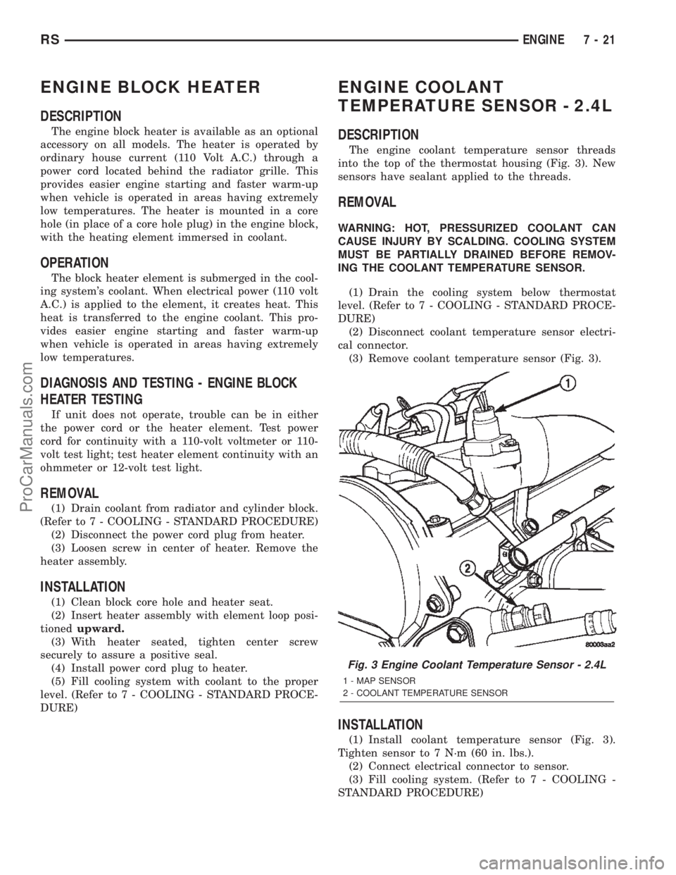
The engine coolant temperature sensor threads
into the top of the thermostat housing (Fig. 3). New
sensors have sealant applied to the threads.
REMOVAL
WARNING: HOT, PRESSURIZED COOLANT CAN
CAUSE INJURY BY SCALDING. COOLING SYSTEM
MUST BE PARTIALLY DRAINED BEFORE REMOV-
ING THE COOLANT TEMPERATURE SENSOR.
(1) Drain the cooling system below thermostat
level. (Refer to 7 - COOLING - STANDARD PROCE-
DURE)
(2) Disconnect coolant temperature sensor electri-
cal connector.
(3) Remove coolant temperature sensor (Fig. 3).
INSTALLATION
(1) Install coolant temperature sensor (Fig. 3).
Tighten sensor to 7 N´m (60 in. lbs.).
(2) Connect electrical connector to sensor.
(3) Fill cooling system. (Refer to 7 - COOLING -
STANDARD PROCEDURE)
Fig. 3 Engine Coolant Temperature Sensor - 2.4L
1 - MAP SENSOR
2 - COOLANT TEMPERATURE SENSOR
RSENGINE7-21
ProCarManuals.com
Page 271 of 2399
ENGINE COOLANT
TEMPERATURE SENSOR -
3.3/3.8L
DESCRIPTION
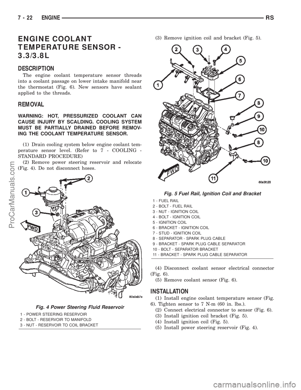
The engine coolant temperature sensor threads
into a coolant passage on lower intake manifold near
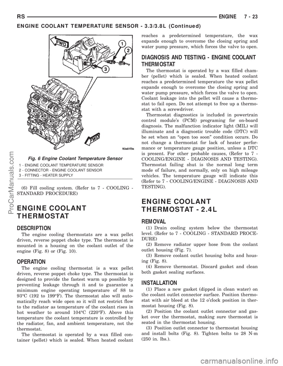
the thermostat (Fig. 6). New sensors have sealant
applied to the threads.
REMOVAL
WARNING: HOT, PRESSURIZED COOLANT CAN
CAUSE INJURY BY SCALDING. COOLING SYSTEM
MUST BE PARTIALLY DRAINED BEFORE REMOV-
ING THE COOLANT TEMPERATURE SENSOR.
(1) Drain cooling system below engine coolant tem-
perature sensor level. (Refer to 7 - COOLING -
STANDARD PROCEDURE)
(2) Remove power steering reservoir and relocate
(Fig. 4). Do not disconnect hoses.(3) Remove ignition coil and bracket (Fig. 5).
(4) Disconnect coolant sensor electrical connector
(Fig. 6).
(5) Remove coolant sensor (Fig. 6).
INSTALLATION
(1) Install engine coolant temperature sensor (Fig.
6). Tighten sensor to 7 N´m (60 in. lbs.).
(2) Connect electrical connector to sensor (Fig. 6).
(3) Install ignition coil bracket (Fig. 5).
(4) Install ignition coil (Fig. 5).
(5) Install power steering reservoir (Fig. 4).
Fig. 4 Power Steering Fluid Reservoir
1 - POWER STEERING RESERVOIR
2 - BOLT - RESERVOIR TO MANIFOLD
3 - NUT - RESERVOIR TO COIL BRACKET
Fig. 5 Fuel Rail, Ignition Coil and Bracket
1 - FUEL RAIL
2 - BOLT - FUEL RAIL
3 - NUT - IGNITION COIL
4 - BOLT - IGNITION COIL
5 - IGNITION COIL
6 - BRACKET - IGNITION COIL
7 - STUD - IGNITION COIL
8 - SEPARATOR - SPARK PLUG CABLE
9 - BRACKET - SPARK PLUG CABLE SEPARATOR
10 - BOLT - SEPARATOR BRACKET
11 - BRACKET - SPARK PLUG CABLE SEPARATOR
7 - 22 ENGINERS
ProCarManuals.com
Page 272 of 2399
(6) Fill cooling system. (Refer to 7 - COOLING -
STANDARD PROCEDURE)
ENGINE COOLANT
THERMOSTAT
DESCRIPTION
The engine cooling thermostats are a wax pellet
driven, reverse poppet choke type. The thermostat is
mounted in a housing on the coolant outlet of the
engine (Fig. 8) or (Fig. 10).
OPERATION
The engine cooling thermostat is a wax pellet
driven, reverse poppet choke type. The thermostat is
designed to provide the fastest warm up possible by
preventing leakage through it and to guarantee a
minimum engine operating temperature of 88 to
93ÉC (192 to 199ÉF). The thermostat also will auto-
matically reach wide open so it will not restrict flow
to the radiator as temperature of the coolant rises in
hot weather to around 104ÉC (220ÉF). Above this
temperature the coolant temperature is controlled by
the radiator, fan, and ambient temperature, not the
thermostat.
The thermostat is operated by a wax filled con-
tainer (pellet) which is sealed. When heated coolantreaches a predetermined temperature, the wax
expands enough to overcome the closing spring and
water pump pressure, which forces the valve to open.
DIAGNOSIS AND TESTING - ENGINE COOLANT
THERMOSTAT
The thermostat is operated by a wax filled cham-
ber (pellet) which is sealed. When heated coolant
reaches a predetermined temperature the wax pellet
expands enough to overcome the closing spring and
water pump pressure, which forces the valve to open.
Coolant leakage into the pellet will cause a thermo-
stat to fail open. Do not attempt to free up a thermo-
stat with a screwdriver.
Thermostat diagnostics is included in powertrain
control module's (PCM) programing for on-board
diagnosis. The malfunction indicator light (MIL) will
illuminate and a diagnostic trouble code (DTC) will
be set when an ªopen too soonº condition occurs. Do
not change a thermostat for lack of heater perfor-
mance or temperature gauge position, unless a DTC
is present. For other probable causes, (Refer to 7 -
COOLING/ENGINE - DIAGNOSIS AND TESTING).
Thermostat failing shut is the normal long term
mode of failure, and normally, only on high mileage
vehicles. The temperature gauge will indicate this
(Refer to 7 - COOLING/ENGINE - DIAGNOSIS AND
TESTING).
ENGINE COOLANT
THERMOSTAT - 2.4L
REMOVAL
(1) Drain cooling system below the thermostat
level. (Refer to 7 - COOLING - STANDARD PROCE-
DURE)
(2) Remove radiator upper hose from the coolant
outlet housing (Fig. 7).
(3) Remove coolant outlet housing bolts and hous-
ing (Fig. 8).
(4) Remove thermostat. Discard gasket and clean
both gasket sealing surfaces.
INSTALLATION
(1) Place a new gasket (dipped in clean water) on
the coolant outlet connector surface. Position thermo-
stat with air bleed at the 12 o'clock position in ther-
mostat housing (Fig. 8).
(2) Position the coolant outlet connector and gas-
ket over the thermostat, making sure thermostat is
seated in the thermostat housing.
(3) Position outlet connector to thermostat housing
and install bolts (Fig. 8). Tighten bolts to 28 N´m
(250 in. lbs.).
Fig. 6 Engine Coolant Temperature Sensor
1 - ENGINE COOLANT TEMPERATURE SENSOR
2 - CONNECTOR - ENGINE COOLANT SENSOR
3 - FITTING - HEATER SUPPLY
RSENGINE7-23
ENGINE COOLANT TEMPERATURE SENSOR - 3.3/3.8L (Continued)
ProCarManuals.com
Page 279 of 2399
DIAGNOSIS AND TESTING - RADIATOR FAN
MOTOR
RADIATOR FAN DIAGNOSIS CHART
CONDITION POSSIBLE CAUSES CORRECTION
NOISY RADIATOR FAN 1. Fan blade loose. 1. Replace fan assembly. (Refer to
7 - COOLING/ENGINE/RADIATOR
FAN - REMOVAL)
2. Fan blade striking a surrounding
object.2. Locate point of fan blade contact
and repair as necessary.
3. Air obstructions at radiator or A/C
condenser.3. Remove obstructions and/or
clean debris.
4. Electric fan motor defective. 4. Replace fan assembly. (Refer to
7 - COOLING/ENGINE/RADIATOR
FAN - REMOVAL)
ELECTRIC FAN MOTOR DOES
NOT OPERATE1. Fan relay, powertrain control
module (PCM), coolant temperature
sensor, or wiring defective.1. (Refer to Appropriate Diagnostic
Information) Repair as necessary.
2. Defective A/C pressure
transducer.2. (Refer to Appropriate Diagnostic
Information) Repair as necessary.
ELECTRIC RADIATOR FAN
OPERATES ALL THE TIME1. Fan relay, powertrain control
module (PCM), coolant temperature
sensor or wiring defective.1. (Refer to Appropriate Diagnostic
Information) Repair as necessary.
2. Check for low coolant level. 2. Add coolant as necessary.
3. Defective A/C pressure
transducer.3. (Refer to Appropriate Diagnostic
Information) Repair as necessary.
REMOVAL
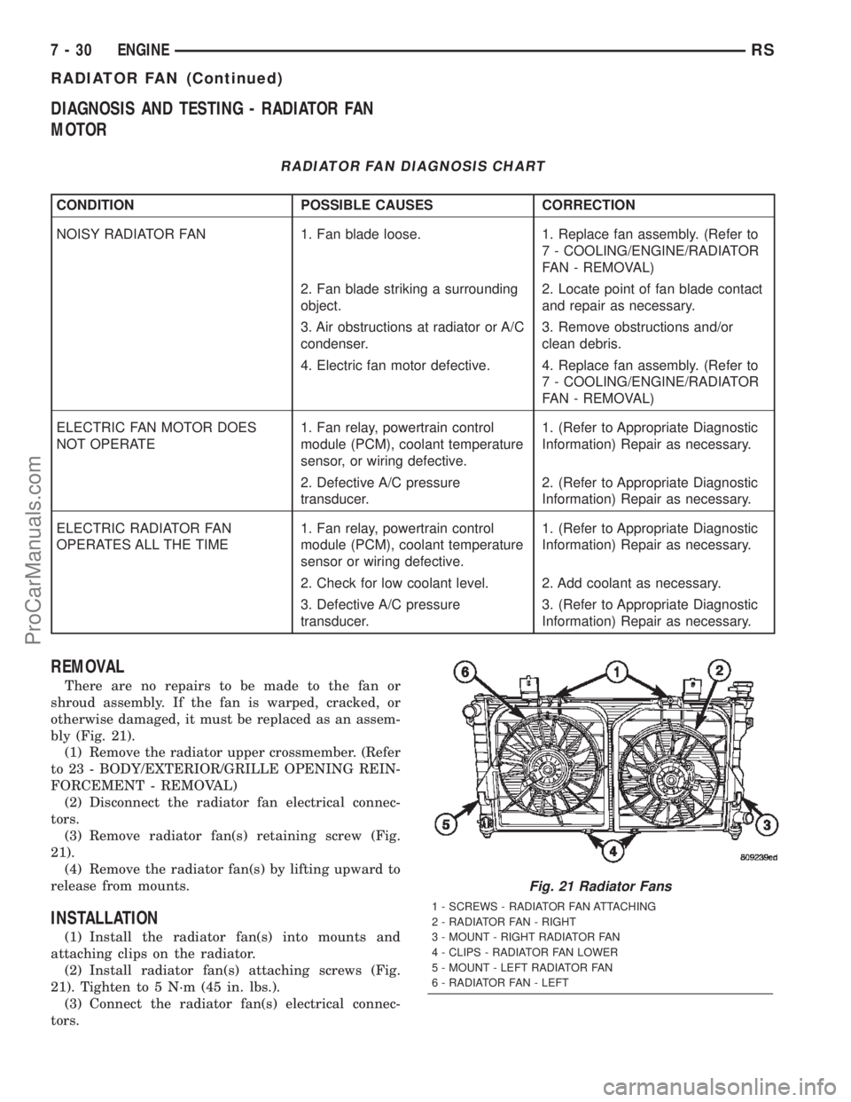
There are no repairs to be made to the fan or
shroud assembly. If the fan is warped, cracked, or
otherwise damaged, it must be replaced as an assem-
bly (Fig. 21).
(1) Remove the radiator upper crossmember. (Refer
to 23 - BODY/EXTERIOR/GRILLE OPENING REIN-
FORCEMENT - REMOVAL)
(2) Disconnect the radiator fan electrical connec-
tors.
(3) Remove radiator fan(s) retaining screw (Fig.
21).
(4) Remove the radiator fan(s) by lifting upward to
release from mounts.
INSTALLATION
(1) Install the radiator fan(s) into mounts and
attaching clips on the radiator.
(2) Install radiator fan(s) attaching screws (Fig.
21). Tighten to 5 N´m (45 in. lbs.).
(3) Connect the radiator fan(s) electrical connec-
tors.
Fig. 21 Radiator Fans
1 - SCREWS - RADIATOR FAN ATTACHING
2 - RADIATOR FAN - RIGHT
3 - MOUNT - RIGHT RADIATOR FAN
4 - CLIPS - RADIATOR FAN LOWER
5 - MOUNT - LEFT RADIATOR FAN
6 - RADIATOR FAN - LEFT
7 - 30 ENGINERS
RADIATOR FAN (Continued)
ProCarManuals.com
Page 291 of 2399
COOLING SYSTEM DIAGNOSIS-DIESEL ENGINE
CONDITION POSSIBLE CAUSES CORRECTION
TEMPERATURE GAUGE
READS LOW1. Diesel engines, due to their
inherent effiency are slower to warm
up than gasoline powered engines,
and will operate at lower
temperatures when the vehicle is
unloaded.1. The low gauge reading may
be normal. Refer to thermostats
in the manual text for
information. See Thermostat
Diagnosis-Diesel Engine.
2. Is the temperature gauge
connected to the temperature gauge
coolant sensor on the engine?2. Check, the engine
temperature sensor connector
in the engine compartment.
3. Is the temperature gauge
operating OK?3. Check gauge operation.
Repair as necessary.
4. Coolant level low in cold ambient
temperatures accompanied with poor
heater performance.4. Check coolant level in the
coolant tank. Inspect system for
leaks. Repair leaks as
necessary. Refer to the Coolant
section for WARNINGS and
precautions before removing
the pressure cap.
5. Improper operation of internal
heater doors or heater controls.5. Inspect heater and repair as
necessary. Refer to Heating
and Air Conditioning for
procedures.
TEMPERATURE GAUGE
READS HIGH. COOLANT
MAY OR MAY NOT BE
LOST OR LEAKING FROM
COOLING SYSTEM1. Trailer is being towed, a steep hill
is being climbed, vehicle is operated
in slow moving traffic, or engine is
being idled with very high ambient
(outside) temperature and the air
conditioning is on. Higher altitudes
could aggravate these conditions.1. This may be a temporary
condition and repair is not
necessary. Turn off the air
conditioning and attempt to
drive the vehicle without any of
the previous conditions.
Observe the temperature
gauge. The gauge should return
to the normal range. If the
gauge does not return to
normal range, determine the
cause for the overheating and
repair.
2. Temperature gauge reading
incorrectly.2. Check gauge. Refer to I/P
group.
3. Coolant low in coolant tank and
radiator.3. Check for coolant leaks and
repair as necessary.
4. Pressure cap not installed tightly.
If cap is loose, boiling point of
coolant will be lowered.4. Tighten cap.
5. Poor seals at pressure/vent cap. 5. (a) Check condition of cap
and cap seals. (b) Check
condition of coolant tank filler
neck. Make sure it does not
leak pressure.
7a - 2 COOLING 2.5L TURBO DIESELRG
COOLING 2.5L TURBO DIESEL (Continued)
ProCarManuals.com
Page 292 of 2399
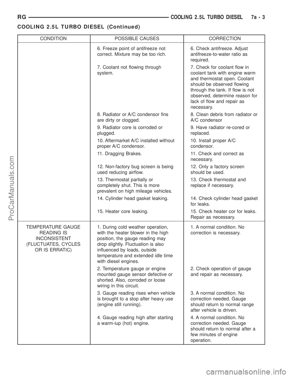
CONDITION POSSIBLE CAUSES CORRECTION
6. Freeze point of antifreeze not
correct. Mixture may be too rich.6. Check antifreeze. Adjust
antifreeze-to-water ratio as
required.
7. Coolant not flowing through
system.7. Check for coolant flow in
coolant tank with engine warm
and thermostat open. Coolant
should be observed flowing
through the tank. If flow is not
observed, determine reason for
lack of flow and repair as
necessary.
8. Radiator or A/C condensor fins
are dirty or clogged.8. Clean debris from radiator or
A/C condensor
9. Radiator core is corroded or
plugged.9. Have radiator re-cored or
replaced.
10. Aftermarket A/C installed without
proper A/C condensor.10. Install proper A/C
condensor.
11. Dragging Brakes. 11. Check and correct as
necessary.
12. Non-factory bug screen is being
used reducing airflow.12. Only a factory screen
should be used.
13. Thermostat partially or
completely shut. This is more
prevalent on high mileage vehicles.13. Check thermostat and
replace if necessary.
14. Cylinder head gasket leaking. 14. Check cylinder head gasket
for leaks.
15. Heater core leaking. 15. Check heater cor for leaks.
Repair as necessary.
TEMPERATURE GAUGE
READING IS
INCONSISTENT
(FLUCTUATES, CYCLES
OR IS ERRATIC)1. During cold weather operation,
with the heater blower in the high
position, the gauge reading may
drop slightly. Fluctuation is also
influenced by loads, outside
temperature and extended idle time
with diesel engines.1. A normal condition. No
correction is necessary.
2. Temperature gauge or engine
mounted gauge sensor defective or
shorted. Also, corroded or loose
wiring in this circuit.2. Check operation of gauge
and repair as necessary.
3. Gauge reading rises when vehicle
is brought to a stop after heavy use
(engine still running).3. A normal condition. No
correction needed. Gauge
should return to normal range
after vehicle is driven.
4. Gauge reading high after starting
a warm-iup (hot) engine.4. A normal condition. No
correction needed. Gauge
should return to normal after a
few minutes of engine
operation.
RGCOOLING 2.5L TURBO DIESEL7a-3
COOLING 2.5L TURBO DIESEL (Continued)
ProCarManuals.com