headlamp CHRYSLER VOYAGER 2002 Service Manual
[x] Cancel search | Manufacturer: CHRYSLER, Model Year: 2002, Model line: VOYAGER, Model: CHRYSLER VOYAGER 2002Pages: 2399, PDF Size: 57.96 MB
Page 6 of 2399
FASTENER USAGE
DESCRIPTION
DESCRIPTION - FASTENER USAGE
WARNING: USE OF AN INCORRECT FASTENER
MAY RESULT IN COMPONENT DAMAGE OR PER-
SONAL INJURY.
Fasteners and torque specifications references in
this Service Manual are identified in metric and SAE
format.
During any maintenance or repair procedures, it is
important to salvage all fasteners (nuts, bolts, etc.)
for reassembly. If the fastener is not salvageable, a
fastener of equivalent specification must be used.
DESCRIPTION - THREADED HOLE REPAIR
Most stripped threaded holes can be repaired using
a Helicoilt. Follow the vehicle or Helicoiltrecommen-
dations for application and repair procedures.
INTERNATIONAL SYMBOLS
DESCRIPTION
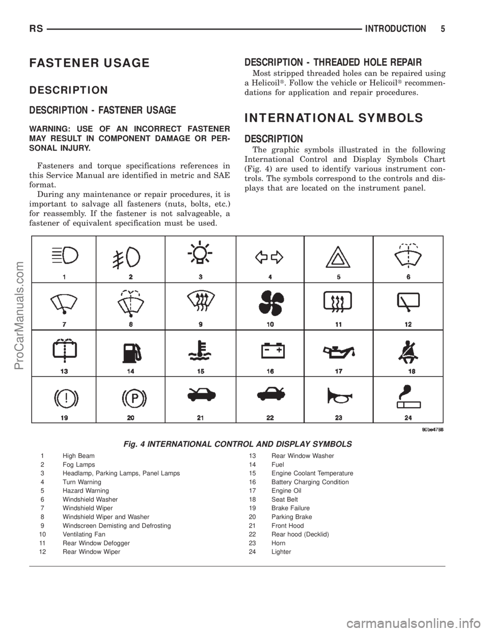
The graphic symbols illustrated in the following
International Control and Display Symbols Chart
(Fig. 4) are used to identify various instrument con-
trols. The symbols correspond to the controls and dis-
plays that are located on the instrument panel.
Fig. 4 INTERNATIONAL CONTROL AND DISPLAY SYMBOLS
1 High Beam 13 Rear Window Washer
2 Fog Lamps 14 Fuel
3 Headlamp, Parking Lamps, Panel Lamps 15 Engine Coolant Temperature
4 Turn Warning 16 Battery Charging Condition
5 Hazard Warning 17 Engine Oil
6 Windshield Washer 18 Seat Belt
7 Windshield Wiper 19 Brake Failure
8 Windshield Wiper and Washer 20 Parking Brake
9 Windscreen Demisting and Defrosting 21 Front Hood
10 Ventilating Fan 22 Rear hood (Decklid)
11 Rear Window Defogger 23 Horn
12 Rear Window Wiper 24 Lighter
RSINTRODUCTION5
ProCarManuals.com
Page 335 of 2399
(a) BCM has two battery feeds at pin 1 and pin
5 of the 6±way connector.
(b) Pin 5 of the (BX2) 32 way connector of the
BCM for ignition feed.
(c) Check voltage (PX2) connector, pin 34 for 12v.
(d) If voltage OK, go to step Step 3
(e) If NO voltage repair as necessary. Refer to
the appropriate wiring information. The wiring
information includes wiring diagrams, proper wire
and connector repair procedures, further details on
wire harness routing and retention, as well as pin-
out and location views for the various wire harness
connectors, splices and grounds.
(3) Check driver's seat belt buckle switch input
(form ORC) for a closed circuit when not buckled. If
input not seen, look for open in wiring or switch. The
switch is grounded when belt is not buckled.
(4) Verify PCI data bus communication between
ORC and BCM.
NO FASTEN SEAT BELT LAMP WHEN IGNITION
SWITCH IS TURNED ON.
(1) Check for burned out lamp.
(2) Using a voltmeter check for voltage at the clus-
ter conncctor:
(a) Pin 2 of the mechanical instrument cluster
for battery feed.
(b) Pin 11 of the mechanical instrument cluster
for ignition voltage.
(3) Repair as necessary.
FASTEN SEAT BELT LAMP OR TONE CONTINUES
FOR MORE THAN 10 SECONDS AFTER SEAT
BELTS ARE FASTENED AND DRIVER'S DOOR IS
CLOSED.
Refer to the proper Body Diagnostic Procedures
manual.
NO TONE WHEN PARK OR HEADLAMPS ARE ON
AND DRIVER'S DOOR IS OPEN.
Make sure ignition is in lock position with the key
removed.
(1) Check the BCM DTC's and BCM sensors to
verify the door is open. Repair as necessary.
(2) Actuate Chime (BCM actuates).
(3) Inspect BCM connectors and wires for proper
connection.
(4) Measure with a voltmeter the voltage (12v) on
BCM connector (PX2) pin 34 with harness connected.
DIAGNOSIS AND TESTING - DOME LAMP ON
CHIME
The dome lamp on chime will warn the driver that
the dome lamps have been left on.When the ignition is OFF and the key is out of the
ignition:
²Driver's door OPEN (door ajar switch is closed to
ground) and
²Dome lamps are ON (dome lamp switch is closed
to ground),
The chime will sound continuously until the driv-
ers door is closed, dome lamps turned OFF or until
the battery protection time out of 15 minutes has
expired. Chime rate: 168 to 192 chimes per minute.
DIAGNOSIS AND TESTING - ENGINE
TEMPERATURE CRITICAL CHIME
The engine temperature critical chime will warn
the driver that the vehicle's engine is overheating.
While monitoring the coolant temperature, the Pow-
ertrain Control Module (PCM) will send on the PCI
data bus as engine temperature every 1.376 seconds
to the cluster. The MIC calculates engine tempera-
ture and determines if a warning should occur. This
feature is functional only with the Ignition Switch in
the Run/Start position.
When the engine temperature reaches 122ÉC
(252ÉF) the MIC requests a chime from the BCM and
the engine temperature lamp comes ON. The MIC
turns OFF the lamp when the engine temperature
reaches 117ÉC (242ÉF). The MIC will chime continu-
ously (request from the BCM). The chime will turn
OFF after four minutes or when the temperature
reaches 117ÉC (242ÉF), which ever occurs first.
DIAGNOSIS AND TESTING - EXTERIOR LAMPS
ON CHIME
The exterior lamp on chime will warn the driver
that the exterior lights have been left on.
With the ignition switch OFF/key out of ignition:
²Driver's door is open (door ajar switch is closed
to ground)
²Parking lamps or headlamps ON (parking lamp
switch is closed to ground)
The chime will sound until lights are turned OFF,
driver's door closed or until the battery protection
time out of 3 minutes has expired.
Chime rate: 168 to 192 chimes per minute.
To test the exterior lamps left on function:
²Turn ignition off
²Remove ignition key
²Turn exterior lamps on with driver's door open.
Chime should sound until lamps are turned off or
driver's door is closed.
DIAGNOSIS AND TESTING - KEY-IN IGNITION
CHIME
The key-in ignition chime will act as a warning to
the driver that the ignition key has been left in the
8B - 2 CHIME/BUZZERRS
CHIME/BUZZER (Continued)
ProCarManuals.com
Page 341 of 2399
interior lamps after 15 minutes after the ignition is
turned off, if they are not turned off by the driver.
²Chime Driver
²Compass/Mini-Trip support.
²Interior Lighting (Courtesy/Reading Lamps)
²BCM Diagnostic Reporting
²Electronic Liftgate Release (with Power Door
Locks)
²Exterior Lighting
²Headlamp Time Delay (with/without Automatic
Headlamps)
²Illuminated Entry
²Fade to Off Interior Lamps - This feature dims
the interior lighting (courtesy lamps) gradually if theBCM does not receive any new inputs that would
cause the interior lamps to remain on.
²Pulse Width Modulated Instrument Panel Dim-
ming
²Door Lock Inhibit - This feature disables the
door lock functions if the key is in the ignition and
either front door is ajar. Pressing the Remote Keyless
Entry (RKE) lock/unlock button under these condi-
tions result in normal lock/unlock activation.
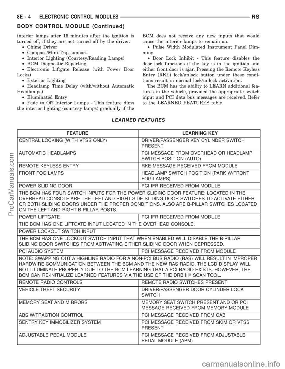
The BCM has the ability to LEARN additional fea-
tures in the vehicle, provided the appropriate switch
input and PCI data bus messages are received. Refer
to the LEARNED FEATURES table.
LEARNED FEATURES
FEATURE LEARNING KEY
CENTRAL LOCKING (WITH VTSS ONLY) DRIVER/PASSENGER KEY CYLINDER SWITCH
PRESENT
AUTOMATIC HEADLAMPS PCI MESSAGE FROM OVERHEAD OR HEADLAMP
SWITCH POSITION (AUTO)
REMOTE KEYLESS ENTRY RKE MESSAGE RECEIVED FROM MODULE
FRONT FOG LAMPS HEADLAMP SWITCH POSITION (PARK W/FRONT
FOG LAMPS)
POWER SLIDING DOOR PCI IFR RECEIVED FROM MODULE
THE BCM HAS FOUR SWITCH INPUTS FOR THE POWER SLIDING DOOR FEATURE; LOCATED IN THE
OVERHEAD CONSOLE ARE THE LEFT AND RIGHT SIDE SLIDING DOOR SWITCHES TO ACTIVATE EITHER
OR BOTH SLIDING DOORS UNDER THE PROPER CONDITIONS. ALSO ARE B-PILLAR SWITCHES LOCATED
ON THE LEFT AND RIGHT B-PILLAR POSTS.
POWER LIFTGATE PCI IFR RECEIVED FROM MODULE
THE BCM HAS ONE LIFTGATE INPUT LOCATED IN THE OVERHEAD CONSOLE.
POWER LOCKOUT SWITCH INPUT
THE BCM HAS ONE LOCKOUT SWITCH INPUT THAT WHEN ENABLED WILL DISABLE THE B-PILLAR
SLIDING DOOR SWITCHES FROM ACTIVATING EITHER SLIDING DOOR WHEN DEPRESSED.
PCI AUDIO SYSTEM PCI MESSAGE RECEIVED FROM MODULE
NOTE: SWAPPING OUT A HIGHLINE RADIO FOR A NON-PCI BUS RADIO (RAS) WILL RESULT IN IMPROPER
HARDWIRE COMMUNICATION BETWEEN THE BCM AND THE NEW RAS RADIO. THE LCD DISPLAY WILL
NOT ILLUMINATE PROPERLY DUE TO THE BCM LEARNING THAT A PCI RADIO EXISTS. HOWEVER, THE
BCM CAN RE-INITIALIZE LEARNED FEATURES VIA THE USE OF THE DRB IIITSCAN TOOL.
REMOTE RADIO CONTROLS REMOTE RADIO SWITCHES PRESENT
VEHICLE THEFT SECURITY DRIVER/PASSENGER DOOR CYLINDER LOCK
SWITCH
MEMORY SEAT AND MIRRORS MEMORY SEAT SWITCH PRESENT AND OR PCI
MESSAGE RECEIVED FROM MEMORY MODULE
ABS W/TRACTION CONTROL PCI MESSAGE RECEIVED FROM CAB
SENTRY KEY IMMOBILIZER SYSTEM PCI MESSAGE RECEIVED FROM SKIM OR VTSS
PRESENT
ADJUSTABLE PEDAL MODULE PCI MESSAGE RECEIVED FROM ADJUSTABLE
PEDAL MODULE (APM)
8E - 4 ELECTRONIC CONTROL MODULESRS
BODY CONTROL MODULE (Continued)
ProCarManuals.com
Page 344 of 2399
(9) Connect a DRBIIItto the vehicle and initialize
the system.
DATA LINK CONNECTOR
DESCRIPTION
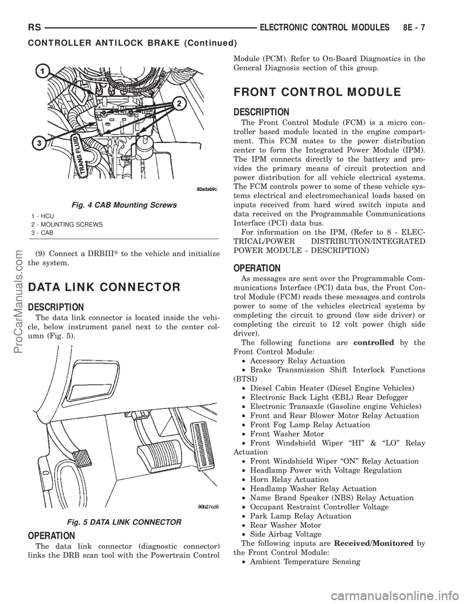
The data link connector is located inside the vehi-
cle, below instrument panel next to the center col-
umn (Fig. 5).
OPERATION
The data link connector (diagnostic connector)
links the DRB scan tool with the Powertrain ControlModule (PCM). Refer to On-Board Diagnostics in the
General Diagnosis section of this group.
FRONT CONTROL MODULE
DESCRIPTION
The Front Control Module (FCM) is a micro con-
troller based module located in the engine compart-
ment. This FCM mates to the power distribution
center to form the Integrated Power Module (IPM).
The IPM connects directly to the battery and pro-
vides the primary means of circuit protection and
power distribution for all vehicle electrical systems.
The FCM controls power to some of these vehicle sys-
tems electrical and electromechanical loads based on
inputs received from hard wired switch inputs and
data received on the Programmable Communications
Interface (PCI) data bus.
For information on the IPM, (Refer to 8 - ELEC-
TRICAL/POWER DISTRIBUTION/INTEGRATED
POWER MODULE - DESCRIPTION)
OPERATION
As messages are sent over the Programmable Com-
munications Interface (PCI) data bus, the Front Con-
trol Module (FCM) reads these messages and controls
power to some of the vehicles electrical systems by
completing the circuit to ground (low side driver) or
completing the circuit to 12 volt power (high side
driver).
The following functions arecontrolledby the
Front Control Module:
²Accessory Relay Actuation
²Brake Transmission Shift Interlock Functions
(BTSI)
²Diesel Cabin Heater (Diesel Engine Vehicles)
²Electronic Back Light (EBL) Rear Defogger
²Electronic Transaxle (Gasoline engine Vehicles)
²Front and Rear Blower Motor Relay Actuation
²Front Fog Lamp Relay Actuation
²Front Washer Motor
²Front Windshield Wiper ªHIº & ªLOº Relay
Actuation
²Front Windshield Wiper ªONº Relay Actuation
²Headlamp Power with Voltage Regulation
²Horn Relay Actuation
²Headlamp Washer Relay Actuation
²Name Brand Speaker (NBS) Relay Actuation
²Occupant Restraint Controller Voltage
²Park Lamp Relay Actuation
²Rear Washer Motor
²Side Airbag Voltage
The following inputs areReceived/Monitoredby
the Front Control Module:
²Ambient Temperature Sensing
Fig. 4 CAB Mounting Screws
1 - HCU
2 - MOUNTING SCREWS
3 - CAB
Fig. 5 DATA LINK CONNECTOR
RSELECTRONIC CONTROL MODULES8E-7
CONTROLLER ANTILOCK BRAKE (Continued)
ProCarManuals.com
Page 346 of 2399
(4) Install the battery in the vehicle. Refer to the
procedure in Battery Systems.
(5) Connect the positive and negative battery
cables.
(6) Using the DRB IIIt, under ªFRONT CON-
TROL MODULEº then ªMISCº program the EQ
curve of the radio into the Front Control Module.
Refer to the appropriate diagnostic manual.
NOTE: If the vehicle is not equipped with Name
Brand Speakers (Infinity, etc.) or Headlamp Washers
the DRB IIITmust be used to Disable the appropri-
ate relays in the Intelligent Power Module Assembly.
HEATED SEAT MODULE
DESCRIPTION
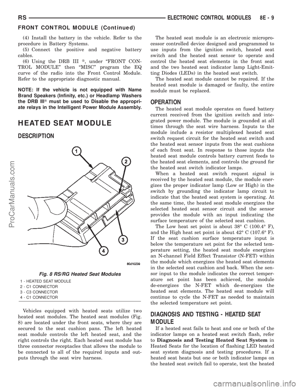
Vehicles equipped with heated seats utilize two
heated seat modules. The heated seat modules (Fig.
8) are located under the front seats, where they are
secured to the seat cushion pans. The left heated
seat module controls the left heated seat, and the
right controls the right. Each heated seat module has
three connector receptacles that allows the module to
be connected to all of the required inputs and out-
puts through the seat wire harness.The heated seat module is an electronic micropro-
cessor controlled device designed and programmed to
use inputs from the ignition switch, heated seat
switch and the heated seat sensor to operate and
control the heated seat elements in the front seat
and the two heated seat indicator lamp Light-Emit-
ting Diodes (LEDs) in the heated seat switch.
The heated seat module cannot be repaired. If the
heated seat module is damaged or faulty, the entire
module must be replaced.
OPERATION
The heated seat module operates on fused battery
current received from the ignition switch and inte-
grated power module. The module is grounded at all
times through the seat wire harness. Inputs to the
module include a resistor multiplexed heated seat
switch request circuit for the heated seat switch and
the heated seat sensor inputs from the seat cushions
of each front seat. In response to those inputs the
heated seat module controls battery current feeds to
the heated seat elements, and controls the ground for
the heated seat switch indicator lamps.
When a heated seat switch request signal is
received by the heated seat module, the module ener-
gizes the proper indicator lamp (Low or High) in the
switch by grounding the indicator lamp circuit to
indicate that the heated seat system is operating. At
the same time, the heated seat module energizes the
selected heated seat sensor circuit and the sensor
provides the module with an input indicating the
surface temperature of the selected seat cushion.
The Low heat set point is about 38É C (100.4É F),
and the High heat set point is about 42É C (107.6É F).
If the seat cushion surface temperature input is
below the temperature set point for the selected tem-
perature setting, the heated seat module energizes
an N-channel Field Effect Transistor (N-FET) within
the module which energizes the heated seat elements
in the selected seat cushion and back. When the sen-
sor input to the module indicates the correct temper-
ature set point has been achieved, the module
de-energizes the N-FET which de-energizes the
heated seat elements. The heated seat module will
continue to cycle the N-FET as needed to maintain
the selected temperature set point.
DIAGNOSIS AND TESTING - HEATED SEAT
MODULE
If a heated seat fails to heat and one or both of the
indicator lamps on a heated seat switch flash, refer
toDiagnosis and Testing Heated Seat Systemin
Heated Seats for the location of flashing LED heated
seat system diagnosis and testing procedures. If a
heated seat heats but one or both indicator lamps on
the heated seat switch fail to operate, test the heated
Fig. 8 RS/RG Heated Seat Modules
1 - HEATED SEAT MODULE
2 - C1 CONNECTOR
3 - C3 CONNECTOR
4 - C1 CONNECTOR
RSELECTRONIC CONTROL MODULES8E-9
FRONT CONTROL MODULE (Continued)
ProCarManuals.com
Page 363 of 2399
(2) Turn the ignition switch on and access the
ªRead Faultº screen.
(3) Record all the DTC's and ªfreeze frameº infor-
mation shown on the DRB scan tool.
(4) To erase DTC's, use the ªErase Trouble Codeº
data screen on the DRB scan tool.Do not erase any
DTC's until problems have been investigated
and repairs have been performed.
OBTAINING DTC'S USING IGNITION KEY
(1) Cycle the ignition key On - Off - On - Off - On
within 5 seconds.
(2) The Odometer will show the P-code for the
DTC code number. Refer to the Emission section for
the DTC chart for a detailed explanation of the DTC
codes.
(3) If no DTC's are present, the cluster will display
one of two texts: ªP1684º and ªdoneº or only ªdoneº.
²P1684 is only a status and indicates that the
PCM memory has been cleared within the last 50
ignition cycles and does not indicate a problem.
²done indicates that NO DTCs are present and
the procedure is complete.
REMOVAL
(1) Disconnect the negative battery cable.
(2) Remove the battery shield, refer to the Battery
section for more information.
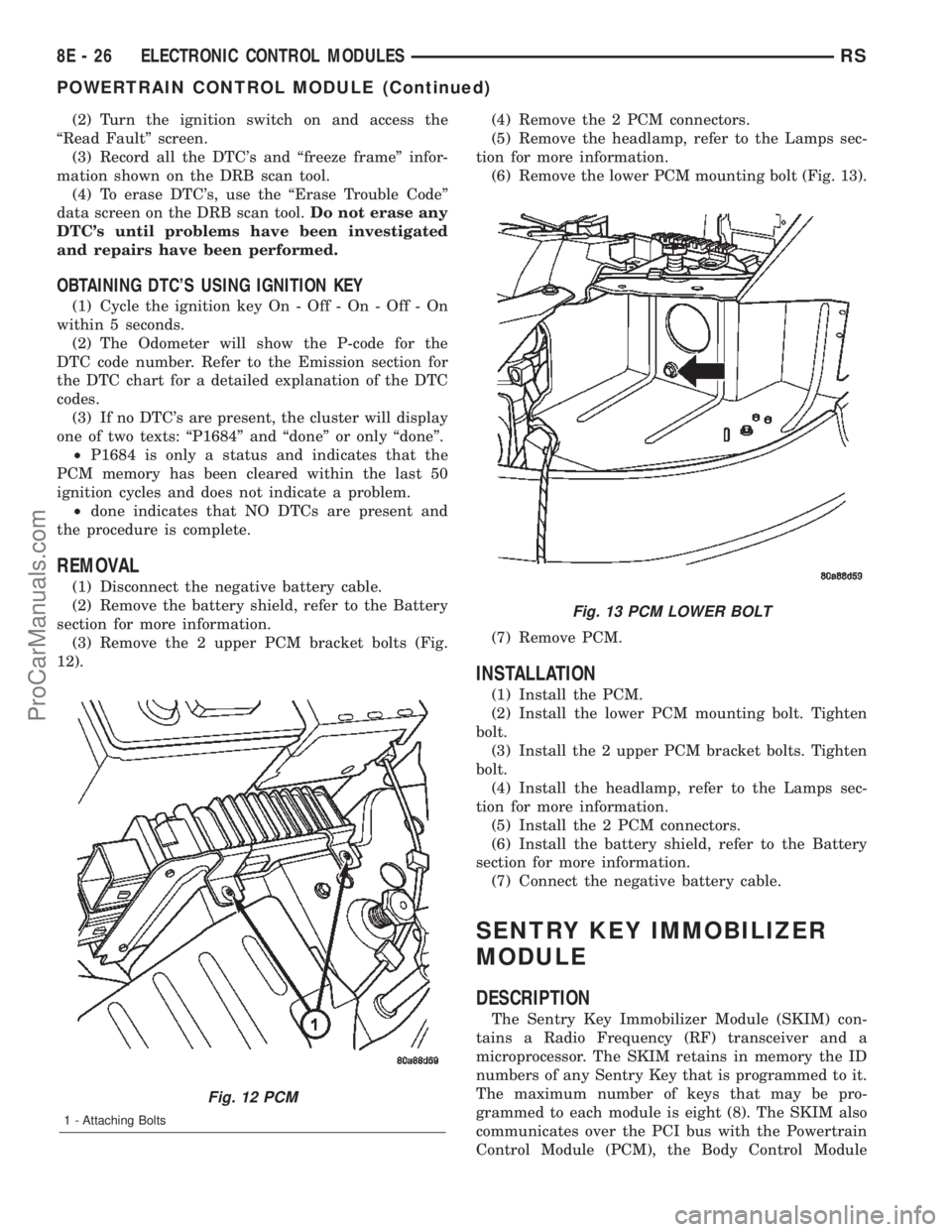
(3) Remove the 2 upper PCM bracket bolts (Fig.
12).(4) Remove the 2 PCM connectors.
(5) Remove the headlamp, refer to the Lamps sec-
tion for more information.
(6) Remove the lower PCM mounting bolt (Fig. 13).
(7) Remove PCM.
INSTALLATION
(1) Install the PCM.
(2) Install the lower PCM mounting bolt. Tighten
bolt.
(3) Install the 2 upper PCM bracket bolts. Tighten
bolt.
(4) Install the headlamp, refer to the Lamps sec-
tion for more information.
(5) Install the 2 PCM connectors.
(6) Install the battery shield, refer to the Battery
section for more information.
(7) Connect the negative battery cable.
SENTRY KEY IMMOBILIZER
MODULE
DESCRIPTION
The Sentry Key Immobilizer Module (SKIM) con-
tains a Radio Frequency (RF) transceiver and a
microprocessor. The SKIM retains in memory the ID
numbers of any Sentry Key that is programmed to it.
The maximum number of keys that may be pro-
grammed to each module is eight (8). The SKIM also
communicates over the PCI bus with the Powertrain
Control Module (PCM), the Body Control Module
Fig. 12 PCM
1 - Attaching Bolts
Fig. 13 PCM LOWER BOLT
8E - 26 ELECTRONIC CONTROL MODULESRS
POWERTRAIN CONTROL MODULE (Continued)
ProCarManuals.com
Page 375 of 2399
Programming Key Failed (Possible Used Key From
Wrong Vehicle) - SKIM is unable to program key due
to one of the following:
²faulty ignition key transponder
²ignition key is programmed to another vehicle.
8 Keys Already Learned, Programming Not Done -
SKIM transponder ID memory is full.
(5) Obtain ignition keys to be programmed from
customer (8 keys maximum).
(6) Using the DRB III, erase all ignition keys by
selecting MISCELLANEOUS and ERASE ALL CUR-
RENT IGN. KEYS.
(7) Program all ignition keys.
Learned Key In Ignition - Ignition key transponder
ID is currently programmed in SKIM memory.
REMOVAL
(1) Disconnect negative battery cable.
(2) Remove left front headlamp module (Refer to 8
- ELECTRICAL/LAMPS/LIGHTING - EXTERIOR/
HEADLAMP UNIT - REMOVAL).
(3) Remove lower headlamp assembly mounting
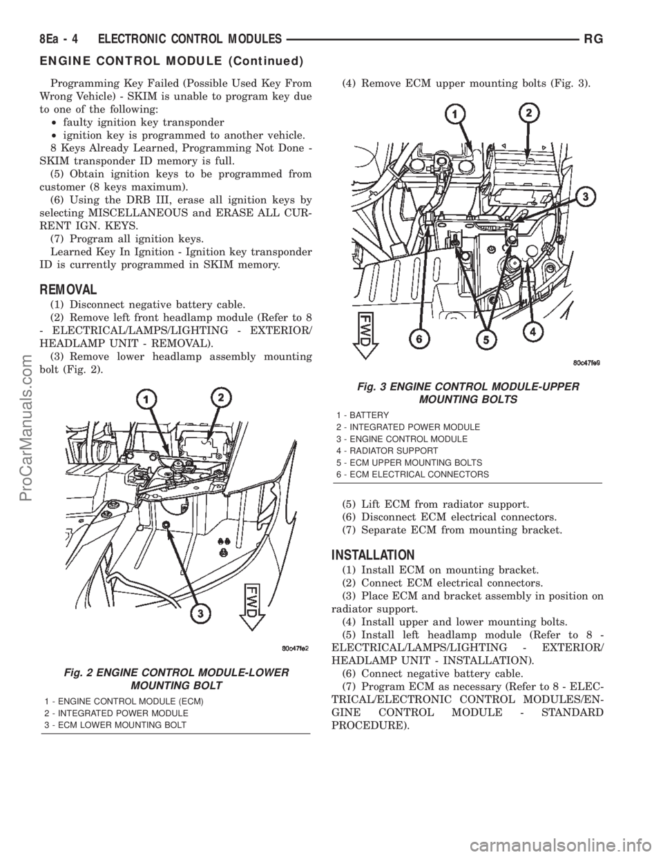
bolt (Fig. 2).(4) Remove ECM upper mounting bolts (Fig. 3).
(5) Lift ECM from radiator support.
(6) Disconnect ECM electrical connectors.
(7) Separate ECM from mounting bracket.
INSTALLATION
(1) Install ECM on mounting bracket.
(2) Connect ECM electrical connectors.
(3) Place ECM and bracket assembly in position on
radiator support.
(4) Install upper and lower mounting bolts.
(5) Install left headlamp module (Refer to 8 -
ELECTRICAL/LAMPS/LIGHTING - EXTERIOR/
HEADLAMP UNIT - INSTALLATION).
(6) Connect negative battery cable.
(7) Program ECM as necessary (Refer to 8 - ELEC-
TRICAL/ELECTRONIC CONTROL MODULES/EN-
GINE CONTROL MODULE - STANDARD
PROCEDURE).
Fig. 2 ENGINE CONTROL MODULE-LOWER
MOUNTING BOLT
1 - ENGINE CONTROL MODULE (ECM)
2 - INTEGRATED POWER MODULE
3 - ECM LOWER MOUNTING BOLT
Fig. 3 ENGINE CONTROL MODULE-UPPER
MOUNTING BOLTS
1 - BATTERY
2 - INTEGRATED POWER MODULE
3 - ENGINE CONTROL MODULE
4 - RADIATOR SUPPORT
5 - ECM UPPER MOUNTING BOLTS
6 - ECM ELECTRICAL CONNECTORS
8Ea - 4 ELECTRONIC CONTROL MODULESRG
ENGINE CONTROL MODULE (Continued)
ProCarManuals.com
Page 388 of 2399

CONVENTIONAL BATTERY CHARGING TIME TABLE
Charging
Amperage5 Amps10
Amps20 Amps
Open Circuit
VoltageHours Charging @ 21É C (70É
F)
12.25 to 12.49 6 hours 3 hours 1.5
hours
12.00 to 12.24 10 hours 5 hours 2.5
hours
10.00 to 11.99 14 hours 7 hours 3.5
hours
Below 10.00 18 hours 9 hours 4.5
hours
STANDARD PROCEDURE - OPEN-CIRCUIT
VOLTAGE TEST
A battery open-circuit voltage (no load) test will
show the approximate state-of-charge of a battery.
This test can be used if no other battery tester is
available.
Before proceeding with this test, completely charge
the battery. Refer to Standard Procedures for the
proper battery charging procedures.
(1) Before measuring the open-circuit voltage, the
surface charge must be removed from the battery.
Turn on the headlamps for fifteen seconds, then
allow up to five minutes for the battery voltage to
stabilize.
(2) Disconnect and isolate both battery cables, neg-
ative cable first.
(3) Using a voltmeter connected to the battery
posts (see the instructions provided by the manufac-
turer of the voltmeter), measure the open-circuit volt-
age (Fig. 9).
See the Open-Circuit Voltage Table. This voltage
reading will indicate the battery state-of-charge, but
will not reveal its cranking capacity. If a battery has
an open-circuit voltage reading of 12.4 volts orgreater, it may be load tested to reveal its cranking
capacity. Refer to Standard Procedures for the proper
battery load test procedures.
OPEN CIRCUIT VOLTAGE TABLE
Open Circuit Voltage Charge Percentage
11.7 volts or less 0%
12.0 volts 25%
12.2 volts 50%
12.45 volts 75%
12.65 volts or more 100%
STANDARD PROCEDURE - IGNITION-OFF
DRAW TEST
The term Ignition-Off Draw (IOD) identifies a nor-
mal condition where power is being drained from the
battery with the ignition switch in the Off position. A
normal vehicle electrical system will draw from five
to thirty-five milliamperes (0.015 to 0.025 ampere)
with the ignition switch in the Off position, and all
non-ignition controlled circuits in proper working
order. Up to twenty-five milliamperes are needed to
enable the memory functions for the Powertrain Con-
trol Module (PCM), digital clock, electronically tuned
radio, and other modules which may vary with the
vehicle equipment.
A vehicle that has not been operated for approxi-
mately twenty-one days, may discharge the battery
to an inadequate level. When a vehicle will not be
used for twenty-one days or more (stored), remove
the IOD fuse from the Integrated Power Module
(IPM). This will reduce battery discharging.
Excessive IOD can be caused by:
²Electrical items left on.
²Faulty or improperly adjusted switches.
²Faulty or shorted electronic modules and compo-
nents.
²An internally shorted generator.
²Intermittent shorts in the wiring.
If the IOD is over twenty-five milliamperes, the
problem must be found and corrected before replac-
ing a battery. In most cases, the battery can be
charged and returned to service after the excessive
IOD condition has been corrected.
(1) Verify that all electrical accessories are off.
Turn off all lamps, remove the ignition key, and close
all doors. If the vehicle is equipped with an illumi-
nated entry system or an electronically tuned radio,
allow the electronic timer function of these systems
to automatically shut off (time out). This may take
up to three minutes.
(2) Disconnect the battery negative cable.
(3) Set an electronic digital multi-meter to its
highest amperage scale. Connect the multi-meter
Fig. 9 Testing Open-Circuit Voltage - Typical
RSBATTERY SYSTEM8F-13
BATTERY (Continued)
ProCarManuals.com
Page 424 of 2399
F). When a fast battery charger is connected to a cold
battery, the current accepted by the battery will be
very low at first. As the battery warms, it will accept
a higher charging current rate (amperage).
²Charger Capacity- A battery charger that
supplies only five amperes will require a longer
charging time. A battery charger that supplies
twenty amperes or more will require a shorter charg-
ing time.
²State-Of-Charge- A completely discharged bat-
tery requires more charging time than a partially
discharged battery. Electrolyte is nearly pure water
in a completely discharged battery. At first, the
charging current (amperage) will be low. As the bat-
tery charges, the specific gravity of the electrolyte
will gradually rise.
The Conventional Battery Charging Time Table
gives an indication of the time required to charge a
typical battery at room temperature based upon the
battery state-of-charge and the charger capacity.
CONVENTIONAL BATTERY CHARGING TIME
TABLE
Charging
Amperage5 Amps10
Amps20 Amps
Open Circuit
VoltageHours Charging @ 21É C (70É F)
12.25 to 12.49 6 hours 3 hours 1.5 hours
12.00 to 12.24 10 hours 5 hours 2.5 hours
10.00 to 11.99 14 hours 7 hours 3.5 hours
Below 10.00 18 hours 9 hours 4.5 hours
STANDARD PROCEDURE - OPEN-CIRCUIT
VOLTAGE TEST
A battery open-circuit voltage (no load) test will show
the approximate state-of-charge of a battery. This test
can be used if no other battery tester is available.
Before proceeding with this test, completely charge
the battery. Refer to Standard Procedures for the
proper battery charging procedures.
(1)
Before measuring the open-circuit voltage, the
surface charge must be removed from the battery.
Turn on the headlamps for fifteen seconds, then allow
up to five minutes for the battery voltage to stabilize.
(2) Disconnect and isolate both battery cables, neg-
ative cable first.
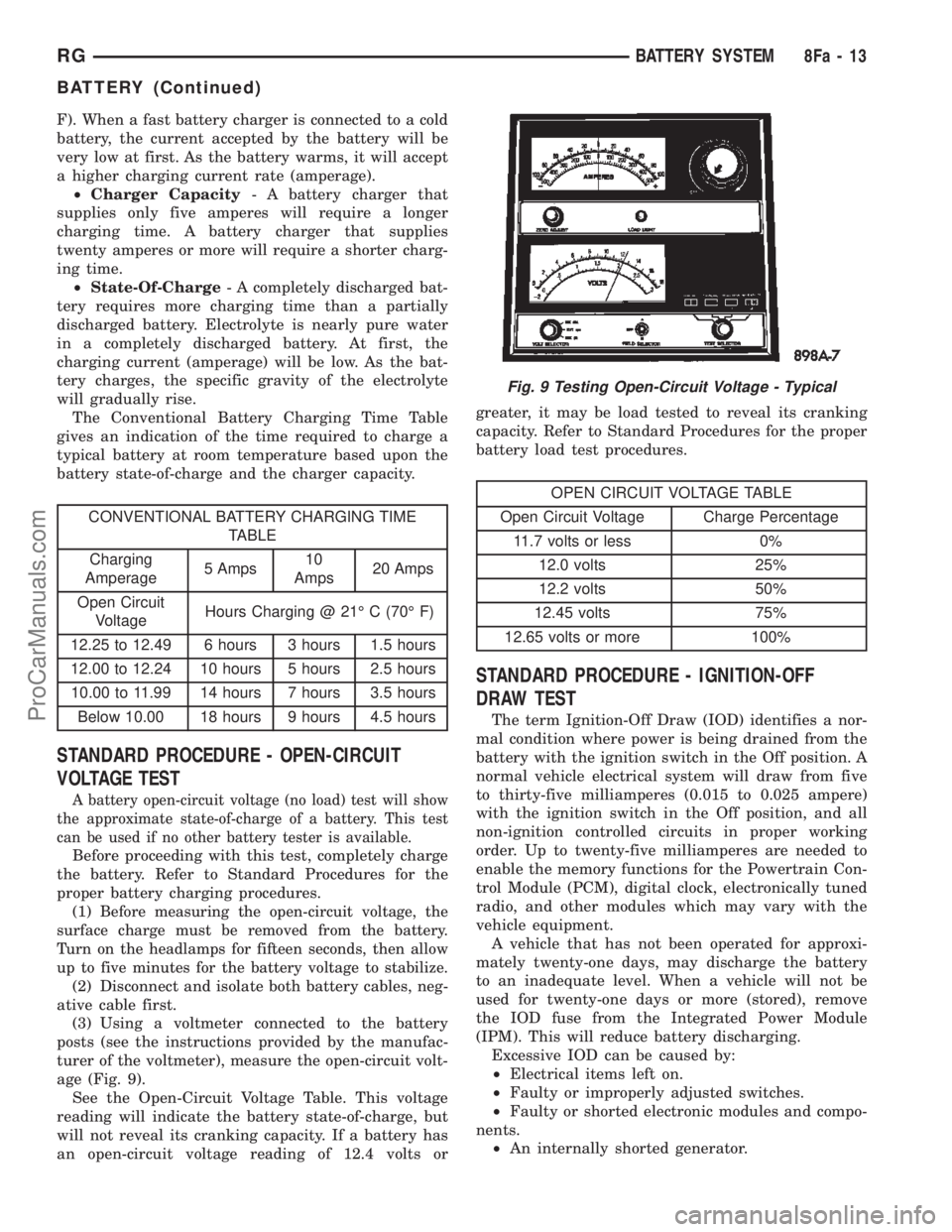
(3) Using a voltmeter connected to the battery
posts (see the instructions provided by the manufac-
turer of the voltmeter), measure the open-circuit volt-
age (Fig. 9).
See the Open-Circuit Voltage Table. This voltage
reading will indicate the battery state-of-charge, but
will not reveal its cranking capacity. If a battery has
an open-circuit voltage reading of 12.4 volts orgreater, it may be load tested to reveal its cranking
capacity. Refer to Standard Procedures for the proper
battery load test procedures.
OPEN CIRCUIT VOLTAGE TABLE
Open Circuit Voltage Charge Percentage
11.7 volts or less 0%
12.0 volts 25%
12.2 volts 50%
12.45 volts 75%
12.65 volts or more 100%
STANDARD PROCEDURE - IGNITION-OFF
DRAW TEST
The term Ignition-Off Draw (IOD) identifies a nor-
mal condition where power is being drained from the
battery with the ignition switch in the Off position. A
normal vehicle electrical system will draw from five
to thirty-five milliamperes (0.015 to 0.025 ampere)
with the ignition switch in the Off position, and all
non-ignition controlled circuits in proper working
order. Up to twenty-five milliamperes are needed to
enable the memory functions for the Powertrain Con-
trol Module (PCM), digital clock, electronically tuned
radio, and other modules which may vary with the
vehicle equipment.
A vehicle that has not been operated for approxi-
mately twenty-one days, may discharge the battery
to an inadequate level. When a vehicle will not be
used for twenty-one days or more (stored), remove
the IOD fuse from the Integrated Power Module
(IPM). This will reduce battery discharging.
Excessive IOD can be caused by:
²Electrical items left on.
²Faulty or improperly adjusted switches.
²Faulty or shorted electronic modules and compo-
nents.
²An internally shorted generator.
Fig. 9 Testing Open-Circuit Voltage - Typical
RGBATTERY SYSTEM8Fa-13
BATTERY (Continued)
ProCarManuals.com
Page 502 of 2399
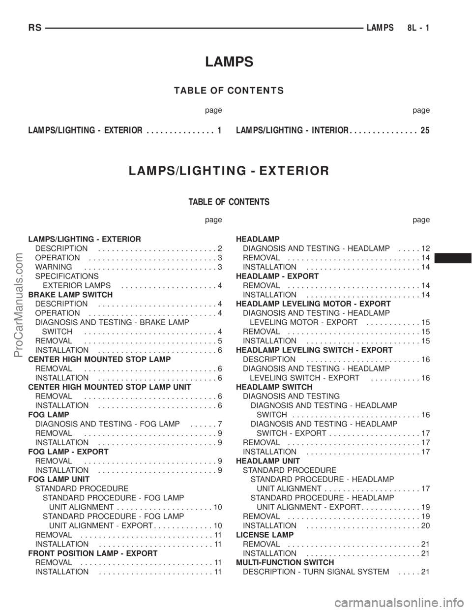
LAMPS
TABLE OF CONTENTS
page page
LAMPS/LIGHTING - EXTERIOR............... 1LAMPS/LIGHTING - INTERIOR............... 25
LAMPS/LIGHTING - EXTERIOR
TABLE OF CONTENTS
page page
LAMPS/LIGHTING - EXTERIOR
DESCRIPTION..........................2
OPERATION............................3
WARNING.............................3
SPECIFICATIONS
EXTERIOR LAMPS.....................4
BRAKE LAMP SWITCH
DESCRIPTION..........................4
OPERATION............................4
DIAGNOSIS AND TESTING - BRAKE LAMP
SWITCH.............................4
REMOVAL.............................5
INSTALLATION..........................6
CENTER HIGH MOUNTED STOP LAMP
REMOVAL.............................6
INSTALLATION..........................6
CENTER HIGH MOUNTED STOP LAMP UNIT
REMOVAL.............................6
INSTALLATION..........................6
FOG LAMP
DIAGNOSIS AND TESTING - FOG LAMP......7
REMOVAL.............................9
INSTALLATION..........................9
FOG LAMP - EXPORT
REMOVAL.............................9
INSTALLATION..........................9
FOG LAMP UNIT
STANDARD PROCEDURE
STANDARD PROCEDURE - FOG LAMP
UNIT ALIGNMENT.....................10
STANDARD PROCEDURE - FOG LAMP
UNIT ALIGNMENT - EXPORT.............10
REMOVAL.............................11
INSTALLATION.........................11
FRONT POSITION LAMP - EXPORT
REMOVAL.............................11
INSTALLATION.........................11HEADLAMP
DIAGNOSIS AND TESTING - HEADLAMP.....12
REMOVAL.............................14
INSTALLATION.........................14
HEADLAMP - EXPORT
REMOVAL.............................14
INSTALLATION.........................14
HEADLAMP LEVELING MOTOR - EXPORT
DIAGNOSIS AND TESTING - HEADLAMP
LEVELING MOTOR - EXPORT............15
REMOVAL.............................15
INSTALLATION.........................15
HEADLAMP LEVELING SWITCH - EXPORT
DESCRIPTION.........................16
DIAGNOSIS AND TESTING - HEADLAMP
LEVELING SWITCH - EXPORT...........16
HEADLAMP SWITCH
DIAGNOSIS AND TESTING
DIAGNOSIS AND TESTING - HEADLAMP
SWITCH............................16
DIAGNOSIS AND TESTING - HEADLAMP
SWITCH - EXPORT....................17
REMOVAL.............................17
INSTALLATION.........................17
HEADLAMP UNIT
STANDARD PROCEDURE
STANDARD PROCEDURE - HEADLAMP
UNIT ALIGNMENT.....................17
STANDARD PROCEDURE - HEADLAMP
UNIT ALIGNMENT - EXPORT.............19
REMOVAL.............................19
INSTALLATION.........................20
LICENSE LAMP
REMOVAL.............................21
INSTALLATION.........................21
MULTI-FUNCTION SWITCH
DESCRIPTION - TURN SIGNAL SYSTEM.....21
RSLAMPS8L-1
ProCarManuals.com