warning CHRYSLER VOYAGER 2002 Owner's Guide
[x] Cancel search | Manufacturer: CHRYSLER, Model Year: 2002, Model line: VOYAGER, Model: CHRYSLER VOYAGER 2002Pages: 2399, PDF Size: 57.96 MB
Page 259 of 2399
CONDITION POSSIBLE CAUSES CORRECTIONS
BELT ROLLED OVER IN GROOVE
OR BELT JUMPS OFF1. Broken cord in belt 1. Replace belt
2. Belt too loose, or too tight 2. (a) Replace belt (auto-tensioned
belts.)
(b) Adjust power steering belt
tension (4 cyl. engine)
3. Misaligned pulleys 3. Align accessories
4. Non-uniform groove or eccentric
pulley4. Replace pulley
DRIVE BELTS - 2.4L
STANDARD PROCEDURE - CHECKING POWER
STEERING BELT TENSION
WARNING: DO NOT CHECK BELT TENSION WITH
ENGINE RUNNING.
Accessory drive belt tension can be measured with
Special Tool 8371 ± Belt Tension Gauge Adapter, and
the DRBIIItusing the following procedures:
(1) Connect 8371 to the DRBIIItfollowing the
instructions provided with tool.
(2) Place end of microphone probe approximately
2.54 cm (1 in.) from belt at belt center span location
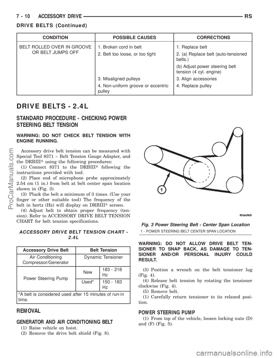
shown in (Fig. 3).
(3) Pluck the belt a minimum of 3 times. (Use your
finger or other suitable tool) The frequency of the
belt in hertz (Hz) will display on DRBIIItscreen.
(4) Adjust belt to obtain proper frequency (ten-
sion). Refer to ACCESSORY DRIVE BELT TENSION
CHART for belt tension specifications.
ACCESSORY DRIVE BELT TENSION CHART -
2.4L
Accessory Drive Belt Belt Tension
Air Conditioning
Compressor/GeneratorDynamic Tensioner
Power Steering PumpNew183 - 218
Hz
Used* 150 - 183
Hz
*A belt is considered used after 15 minutes of run-in
time.
REMOVAL
GENERATOR AND AIR CONDITIONING BELT
(1) Raise vehicle on hoist.
(2) Remove the drive belt shield (Fig. 8).WARNING: DO NOT ALLOW DRIVE BELT TEN-
SIONER TO SNAP BACK, AS DAMAGE TO TEN-
SIONER AND/OR PERSONAL INJURY COULD
RESULT.
(3) Position a wrench on the belt tensioner lug
(Fig. 4).
(4) Release belt tension by rotating the tensioner
clockwise (Fig. 4).
(5) Remove belt.
(1) Carefully return tensioner to its relaxed posi-
tion.
POWER STEERING PUMP
(1) From top of the vehicle, loosen locking nuts (D)
and (F) (Fig. 5).
Fig. 3 Power Steering Belt - Center Span Location
1 - POWER STEERING BELT CENTER SPAN LOCATION
7 - 10 ACCESSORY DRIVERS
DRIVE BELTS (Continued)
ProCarManuals.com
Page 261 of 2399
POWER STEERING PUMP
(1) Install belt over crankshaft and power steering
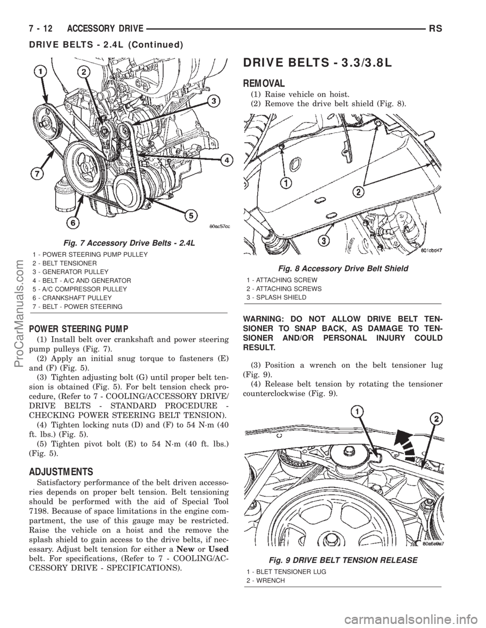
pump pulleys (Fig. 7).
(2) Apply an initial snug torque to fasteners (E)
and (F) (Fig. 5).
(3) Tighten adjusting bolt (G) until proper belt ten-
sion is obtained (Fig. 5). For belt tension check pro-
cedure, (Refer to 7 - COOLING/ACCESSORY DRIVE/
DRIVE BELTS - STANDARD PROCEDURE -
CHECKING POWER STEERING BELT TENSION).
(4) Tighten locking nuts (D) and (F) to 54 N´m (40
ft. lbs.) (Fig. 5).
(5) Tighten pivot bolt (E) to 54 N´m (40 ft. lbs.)
(Fig. 5).
ADJUSTMENTS
Satisfactory performance of the belt driven accesso-
ries depends on proper belt tension. Belt tensioning
should be performed with the aid of Special Tool
7198. Because of space limitations in the engine com-
partment, the use of this gauge may be restricted.
Raise the vehicle on a hoist and the remove the
splash shield to gain access to the drive belts, if nec-
essary. Adjust belt tension for either aNeworUsed
belt. For specifications, (Refer to 7 - COOLING/AC-
CESSORY DRIVE - SPECIFICATIONS).
DRIVE BELTS - 3.3/3.8L
REMOVAL
(1) Raise vehicle on hoist.
(2) Remove the drive belt shield (Fig. 8).
WARNING: DO NOT ALLOW DRIVE BELT TEN-
SIONER TO SNAP BACK, AS DAMAGE TO TEN-
SIONER AND/OR PERSONAL INJURY COULD
RESULT.
(3) Position a wrench on the belt tensioner lug
(Fig. 9).
(4) Release belt tension by rotating the tensioner
counterclockwise (Fig. 9).
Fig. 7 Accessory Drive Belts - 2.4L
1 - POWER STEERING PUMP PULLEY
2 - BELT TENSIONER
3 - GENERATOR PULLEY
4 - BELT - A/C AND GENERATOR
5 - A/C COMPRESSOR PULLEY
6 - CRANKSHAFT PULLEY
7 - BELT - POWER STEERING
Fig. 8 Accessory Drive Belt Shield
1 - ATTACHING SCREW
2 - ATTACHING SCREWS
3 - SPLASH SHIELD
Fig. 9 DRIVE BELT TENSION RELEASE
1 - BLET TENSIONER LUG
2 - WRENCH
7 - 12 ACCESSORY DRIVERS
DRIVE BELTS - 2.4L (Continued)
ProCarManuals.com
Page 270 of 2399
ENGINE BLOCK HEATER
DESCRIPTION
The engine block heater is available as an optional
accessory on all models. The heater is operated by
ordinary house current (110 Volt A.C.) through a
power cord located behind the radiator grille. This
provides easier engine starting and faster warm-up
when vehicle is operated in areas having extremely
low temperatures. The heater is mounted in a core
hole (in place of a core hole plug) in the engine block,
with the heating element immersed in coolant.
OPERATION
The block heater element is submerged in the cool-
ing system's coolant. When electrical power (110 volt
A.C.) is applied to the element, it creates heat. This
heat is transferred to the engine coolant. This pro-
vides easier engine starting and faster warm-up
when vehicle is operated in areas having extremely
low temperatures.
DIAGNOSIS AND TESTING - ENGINE BLOCK
HEATER TESTING
If unit does not operate, trouble can be in either
the power cord or the heater element. Test power
cord for continuity with a 110-volt voltmeter or 110-
volt test light; test heater element continuity with an
ohmmeter or 12-volt test light.
REMOVAL
(1) Drain coolant from radiator and cylinder block.
(Refer to 7 - COOLING - STANDARD PROCEDURE)
(2) Disconnect the power cord plug from heater.
(3) Loosen screw in center of heater. Remove the
heater assembly.
INSTALLATION
(1) Clean block core hole and heater seat.
(2) Insert heater assembly with element loop posi-
tionedupward.
(3) With heater seated, tighten center screw
securely to assure a positive seal.
(4) Install power cord plug to heater.
(5) Fill cooling system with coolant to the proper
level. (Refer to 7 - COOLING - STANDARD PROCE-
DURE)
ENGINE COOLANT
TEMPERATURE SENSOR - 2.4L
DESCRIPTION
The engine coolant temperature sensor threads
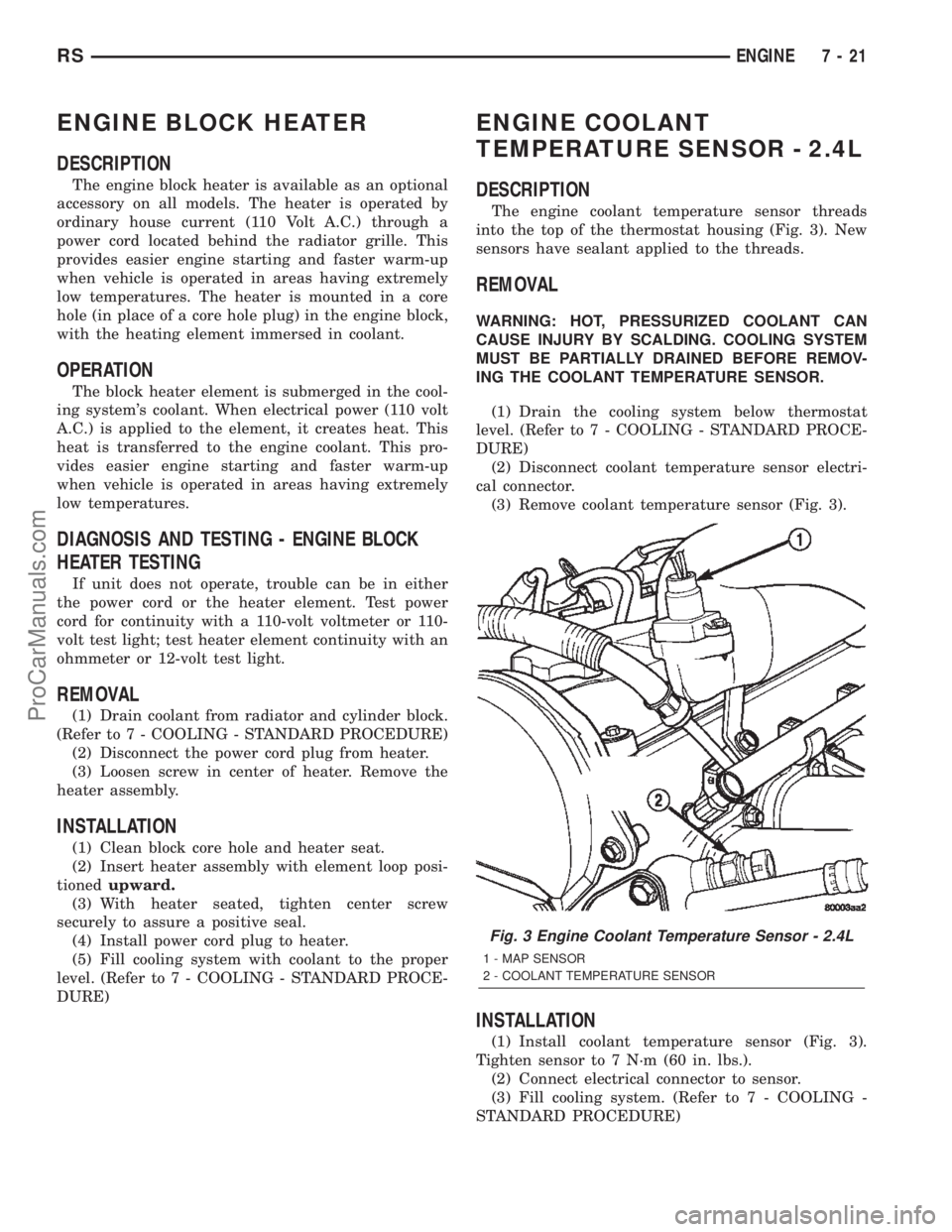
into the top of the thermostat housing (Fig. 3). New
sensors have sealant applied to the threads.
REMOVAL
WARNING: HOT, PRESSURIZED COOLANT CAN
CAUSE INJURY BY SCALDING. COOLING SYSTEM
MUST BE PARTIALLY DRAINED BEFORE REMOV-
ING THE COOLANT TEMPERATURE SENSOR.
(1) Drain the cooling system below thermostat
level. (Refer to 7 - COOLING - STANDARD PROCE-
DURE)
(2) Disconnect coolant temperature sensor electri-
cal connector.
(3) Remove coolant temperature sensor (Fig. 3).
INSTALLATION
(1) Install coolant temperature sensor (Fig. 3).
Tighten sensor to 7 N´m (60 in. lbs.).
(2) Connect electrical connector to sensor.
(3) Fill cooling system. (Refer to 7 - COOLING -
STANDARD PROCEDURE)
Fig. 3 Engine Coolant Temperature Sensor - 2.4L
1 - MAP SENSOR
2 - COOLANT TEMPERATURE SENSOR
RSENGINE7-21
ProCarManuals.com
Page 271 of 2399
ENGINE COOLANT
TEMPERATURE SENSOR -
3.3/3.8L
DESCRIPTION
The engine coolant temperature sensor threads
into a coolant passage on lower intake manifold near
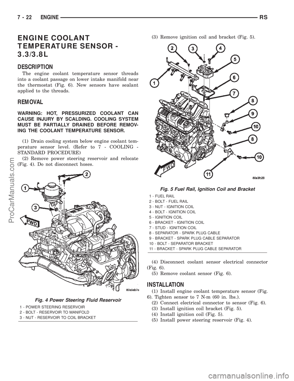
the thermostat (Fig. 6). New sensors have sealant
applied to the threads.
REMOVAL
WARNING: HOT, PRESSURIZED COOLANT CAN
CAUSE INJURY BY SCALDING. COOLING SYSTEM
MUST BE PARTIALLY DRAINED BEFORE REMOV-
ING THE COOLANT TEMPERATURE SENSOR.
(1) Drain cooling system below engine coolant tem-
perature sensor level. (Refer to 7 - COOLING -
STANDARD PROCEDURE)
(2) Remove power steering reservoir and relocate
(Fig. 4). Do not disconnect hoses.(3) Remove ignition coil and bracket (Fig. 5).
(4) Disconnect coolant sensor electrical connector
(Fig. 6).
(5) Remove coolant sensor (Fig. 6).
INSTALLATION
(1) Install engine coolant temperature sensor (Fig.
6). Tighten sensor to 7 N´m (60 in. lbs.).
(2) Connect electrical connector to sensor (Fig. 6).
(3) Install ignition coil bracket (Fig. 5).
(4) Install ignition coil (Fig. 5).
(5) Install power steering reservoir (Fig. 4).
Fig. 4 Power Steering Fluid Reservoir
1 - POWER STEERING RESERVOIR
2 - BOLT - RESERVOIR TO MANIFOLD
3 - NUT - RESERVOIR TO COIL BRACKET
Fig. 5 Fuel Rail, Ignition Coil and Bracket
1 - FUEL RAIL
2 - BOLT - FUEL RAIL
3 - NUT - IGNITION COIL
4 - BOLT - IGNITION COIL
5 - IGNITION COIL
6 - BRACKET - IGNITION COIL
7 - STUD - IGNITION COIL
8 - SEPARATOR - SPARK PLUG CABLE
9 - BRACKET - SPARK PLUG CABLE SEPARATOR
10 - BOLT - SEPARATOR BRACKET
11 - BRACKET - SPARK PLUG CABLE SEPARATOR
7 - 22 ENGINERS
ProCarManuals.com
Page 274 of 2399
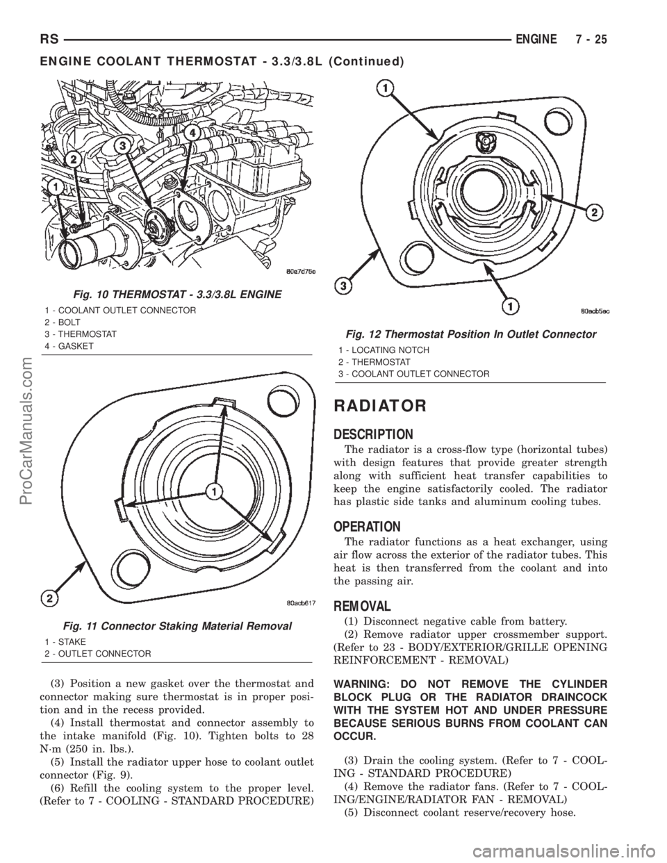
(3) Position a new gasket over the thermostat and
connector making sure thermostat is in proper posi-
tion and in the recess provided.
(4) Install thermostat and connector assembly to
the intake manifold (Fig. 10). Tighten bolts to 28
N´m (250 in. lbs.).
(5) Install the radiator upper hose to coolant outlet
connector (Fig. 9).
(6) Refill the cooling system to the proper level.
(Refer to 7 - COOLING - STANDARD PROCEDURE)
RADIATOR
DESCRIPTION
The radiator is a cross-flow type (horizontal tubes)
with design features that provide greater strength
along with sufficient heat transfer capabilities to
keep the engine satisfactorily cooled. The radiator
has plastic side tanks and aluminum cooling tubes.
OPERATION
The radiator functions as a heat exchanger, using
air flow across the exterior of the radiator tubes. This
heat is then transferred from the coolant and into
the passing air.
REMOVAL
(1) Disconnect negative cable from battery.
(2) Remove radiator upper crossmember support.
(Refer to 23 - BODY/EXTERIOR/GRILLE OPENING
REINFORCEMENT - REMOVAL)
WARNING: DO NOT REMOVE THE CYLINDER
BLOCK PLUG OR THE RADIATOR DRAINCOCK
WITH THE SYSTEM HOT AND UNDER PRESSURE
BECAUSE SERIOUS BURNS FROM COOLANT CAN
OCCUR.
(3) Drain the cooling system. (Refer to 7 - COOL-
ING - STANDARD PROCEDURE)
(4) Remove the radiator fans. (Refer to 7 - COOL-
ING/ENGINE/RADIATOR FAN - REMOVAL)
(5) Disconnect coolant reserve/recovery hose.
Fig. 10 THERMOSTAT - 3.3/3.8L ENGINE
1 - COOLANT OUTLET CONNECTOR
2 - BOLT
3 - THERMOSTAT
4 - GASKET
Fig. 11 Connector Staking Material Removal
1-STAKE
2 - OUTLET CONNECTOR
Fig. 12 Thermostat Position In Outlet Connector
1 - LOCATING NOTCH
2 - THERMOSTAT
3 - COOLANT OUTLET CONNECTOR
RSENGINE7-25
ENGINE COOLANT THERMOSTAT - 3.3/3.8L (Continued)
ProCarManuals.com
Page 277 of 2399
DIAGNOSIS AND TESTING
DIAGNOSIS AND TESTING - COOLING SYSTEM
PRESSURE CAP TESTING
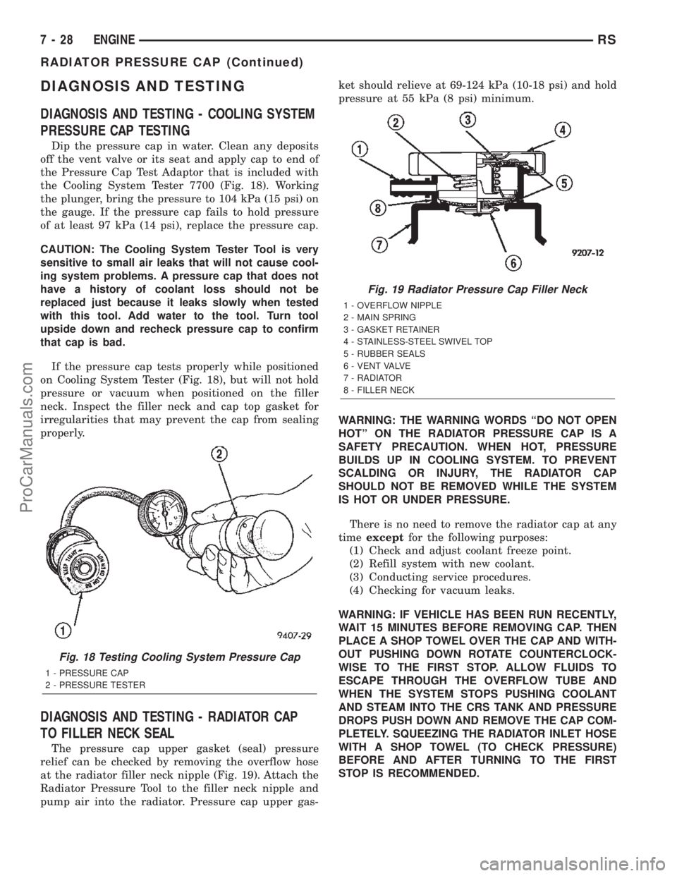
Dip the pressure cap in water. Clean any deposits
off the vent valve or its seat and apply cap to end of
the Pressure Cap Test Adaptor that is included with
the Cooling System Tester 7700 (Fig. 18). Working
the plunger, bring the pressure to 104 kPa (15 psi) on
the gauge. If the pressure cap fails to hold pressure
of at least 97 kPa (14 psi), replace the pressure cap.
CAUTION: The Cooling System Tester Tool is very
sensitive to small air leaks that will not cause cool-
ing system problems. A pressure cap that does not
have a history of coolant loss should not be
replaced just because it leaks slowly when tested
with this tool. Add water to the tool. Turn tool
upside down and recheck pressure cap to confirm
that cap is bad.
If the pressure cap tests properly while positioned
on Cooling System Tester (Fig. 18), but will not hold
pressure or vacuum when positioned on the filler
neck. Inspect the filler neck and cap top gasket for
irregularities that may prevent the cap from sealing
properly.
DIAGNOSIS AND TESTING - RADIATOR CAP
TO FILLER NECK SEAL
The pressure cap upper gasket (seal) pressure
relief can be checked by removing the overflow hose
at the radiator filler neck nipple (Fig. 19). Attach the
Radiator Pressure Tool to the filler neck nipple and
pump air into the radiator. Pressure cap upper gas-ket should relieve at 69-124 kPa (10-18 psi) and hold
pressure at 55 kPa (8 psi) minimum.
WARNING: THE WARNING WORDS ªDO NOT OPEN
HOTº ON THE RADIATOR PRESSURE CAP IS A
SAFETY PRECAUTION. WHEN HOT, PRESSURE
BUILDS UP IN COOLING SYSTEM. TO PREVENT
SCALDING OR INJURY, THE RADIATOR CAP
SHOULD NOT BE REMOVED WHILE THE SYSTEM
IS HOT OR UNDER PRESSURE.
There is no need to remove the radiator cap at any
timeexceptfor the following purposes:
(1) Check and adjust coolant freeze point.
(2) Refill system with new coolant.
(3) Conducting service procedures.
(4) Checking for vacuum leaks.
WARNING: IF VEHICLE HAS BEEN RUN RECENTLY,
WAIT 15 MINUTES BEFORE REMOVING CAP. THEN
PLACE A SHOP TOWEL OVER THE CAP AND WITH-
OUT PUSHING DOWN ROTATE COUNTERCLOCK-
WISE TO THE FIRST STOP. ALLOW FLUIDS TO
ESCAPE THROUGH THE OVERFLOW TUBE AND
WHEN THE SYSTEM STOPS PUSHING COOLANT
AND STEAM INTO THE CRS TANK AND PRESSURE
DROPS PUSH DOWN AND REMOVE THE CAP COM-
PLETELY. SQUEEZING THE RADIATOR INLET HOSE
WITH A SHOP TOWEL (TO CHECK PRESSURE)
BEFORE AND AFTER TURNING TO THE FIRST
STOP IS RECOMMENDED.
Fig. 18 Testing Cooling System Pressure Cap
1 - PRESSURE CAP
2 - PRESSURE TESTER
Fig. 19 Radiator Pressure Cap Filler Neck
1 - OVERFLOW NIPPLE
2 - MAIN SPRING
3 - GASKET RETAINER
4 - STAINLESS-STEEL SWIVEL TOP
5 - RUBBER SEALS
6 - VENT VALVE
7 - RADIATOR
8 - FILLER NECK
7 - 28 ENGINERS
RADIATOR PRESSURE CAP (Continued)
ProCarManuals.com
Page 287 of 2399
TRANSMISSION
TABLE OF CONTENTS
page page
TRANSMISSION
STANDARD PROCEDURE - FLUSHING
COOLERS AND TUBES.................38
TRANSMISSION OIL COOLER
DESCRIPTION.........................38
REMOVAL.............................38CLEANING............................39
INSPECTION..........................39
INSTALLATION.........................39
TRANSMISSION OIL COOLER LINES
REMOVAL.............................39
INSTALLATION.........................40
TRANSMISSION
STANDARD PROCEDURE - FLUSHING
COOLERS AND TUBES
The recommended procedure for cooler flushing is
to use Tool 6906 Cooler Flusher.
WARNING: WEAR PROTECTIVE EYEWEAR THAT
MEETS THE REQUIREMENTS OF OSHA AND ANSI
Z87.1±1968. WEAR STANDARD INDUSTRIAL RUB-
BER GLOVES. KEEP LIT CIGARETTES, SPARKS,
FLAMES, AND OTHER IGNITION SOURCES AWAY
FROM THE AREA TO PREVENT THE IGNITION OF
COMBUSTIBLE LIQUIDS AND GASES. KEEP A
CLASS (B) FIRE EXTINGUISHER IN THE AREA
WHERE THE FLUSHER WILL BE USED.
WARNING: KEEP THE AREA WELL VENTILATED.
DO NOT LET FLUSHING SOLVENT COME IN CON-
TACT WITH YOUR EYES OR SKIN: IF EYE CONTAM-
INATION OCCURS, FLUSH EYES WITH WATER FOR
15 TO 20 SECONDS. REMOVE CONTAMINATED
CLOTHING AND WASH AFFECTED SKIN WITH
SOAP AND WATER. SEEK MEDICAL ATTENTION.
(1) Remove cover plate filler plug on Tool 6906.
Fill reservoir 1/2 to 3/4 full of fresh flushing solution.
Use MopartTransmission Cooler Flush (MS-552) or
equivalent solution conforming to MS-552. Flushing
solvents are petroleum based solutions generally
used to clean automatic transmission components.
DO NOTuse solvents containing acids, water, gaso-
line, or any other corrosive liquids.
(2) Reinstall filler plug on Tool 6906.
(3) Verify pump power switch is turned OFF. Con-
nect red alligator clip to positive (+) battery post.
Connect black (-) alligator clip to a good ground.
NOTE: When flushing transmission cooler and
lines, ALWAYS reverse flush.(4) Connect the BLUE pressure line to the OUT-
LET (From) cooler line.
(5) Connect the CLEAR return line to the INLET
(To) cooler line
(6) Turn pump ON for two to three minutes to
flush cooler and lines.
(7) Turn pump OFF.
(8) Disconnect CLEAR suction line from reservoir
at cover plate. Disconnect CLEAR return line at
cover plate, and place it in a drain pan.
(9) Turn pump ON for 30 seconds to purge flush-
ing solution from cooler and lines. Turn pump OFF.
(10) Place CLEAR suction line into a one quart
container of MopartATF+4 (Automatic Transmission
FluidÐType 9602).
(11) Turn pump ON until all transmission fluid is
removed from the one quart container and lines. This
purges any residual cleaning solvent from the trans-
mission cooler and lines. Turn pump OFF.
(12) Disconnect alligator clips from battery. Recon-
nect flusher lines to cover plate, and remove flushing
adapters from cooler lines.
TRANSMISSION OIL COOLER
DESCRIPTION
The transmission oil cooler is an oil-to-air type
cooler that is mounted between the front of the radi-
ator and back side of the A/C condenser (Fig. 2). Use
only approved transmission oil cooler hoses that are
molded to fit the space available.
REMOVAL
(1) Remove the radiator. (Refer to 7 - COOLING/
ENGINE/RADIATOR - REMOVAL)
(2) Disconnect lines from oil cooler (Fig. 1).
(3) Remove oil cooler attaching screws (Fig. 2).
(4) Remove the oil cooler.
7 - 38 TRANSMISSIONRS
ProCarManuals.com
Page 290 of 2399
COOLING 2.5L TURBO DIESEL
TABLE OF CONTENTS
page page
COOLING 2.5L TURBO DIESEL
DESCRIPTION - COOLING SYSTEM.........1
DIAGNOSIS AND TESTING
DIAGNOSIS AND TESTING - COOLING
SYSTEM.............................1
DIAGNOSIS AND TESTING - COOLING
SYSTEM LEAK TEST....................6
DIAGNOSIS AND TESTING - COOLING
SYSTEM FLOW CHECK.................7
DIAGNOSIS AND TESTING - COOLING
SYSTEM AERATION....................7CLEANING.............................7
INSPECTION...........................7
SPECIFICATIONS
SPECIFICATIONS - TORQUE.............8
SPECIFICATIONS - COOLING SYSTEM
CAPACITY............................8
ACCESSORY DRIVE.......................9
ENGINE...............................14
COOLING 2.5L TURBO DIESEL
DESCRIPTION - COOLING SYSTEM
The cooling system regulates engine operating tem-
perature. It allows the engine to reach normal oper-
ating temperature as quickly as possible, maintains
normal operating temperature and prevents over-
heating.
The cooling system also provides a means of heat-
ing the passenger compartment. The cooling system
is pressurized and uses a centrifugal water pump to
circulate coolant throughout the system. A separate
and remotely mounted, pressurized coolant tank
using a pressure/vent cap is used.
COOLING SYSTEM COMPONENTS
The cooling system consists of:
²Charge Air Cooler
²Electric Cooling Fans
²A aluminum-core radiator with plastic side
tanks
²A separate pressurized coolant tank
²A pressure/vent cap on the coolant tank
²Fan shroud
²Thermostat
²Coolant
²Low coolant warning lamp
²Coolant temperature gauge
²Water pump
²Hoses and hose clamps
DIAGNOSIS AND TESTING
DIAGNOSIS AND TESTING - COOLING SYSTEM
Establish what driving conditions caused the com-
plaint. Abnormal loads on the cooling system such as
the following may be the cause:
(1) PROLONGED IDLE, VERY HIGH AMBIENT
TEMPERATURE, SLIGHT TAIL WIND AT IDLE,
SLOW TRAFFIC, TRAFFIC JAMS, HIGH SPEED
OR STEEP GRADES.
Driving techniques that avoid overheating are:
²Idle with A/C off when temperature gauge is at
end of normal range.
²Increasing engine speed for more air flow is rec-
ommended.
(2) TRAILER TOWING:
Consult Trailer Towing section of owners manual.
Do not exceed limits.
(3) RECENT SERVICE OR ACCIDENT REPAIR:
Determine if any recent service has been per-
formed on vehicle that may effect cooling system.
This may be:
²Engine adjustments (incorrect timing)
²Slipping engine accessory drive belt
²Brakes (possibly dragging)
²Changed parts (incorrect water pump)
²Reconditioned radiator or cooling system refill-
ing (possibly under filled or air trapped in system).
NOTE: If investigation reveals none of the previous
items as a cause for an engine overheating com-
plaint, refer to following Cooling System Diagnosis
charts.
These charts are to be used as a quick-reference
only.
RGCOOLING 2.5L TURBO DIESEL7a-1
ProCarManuals.com
Page 291 of 2399
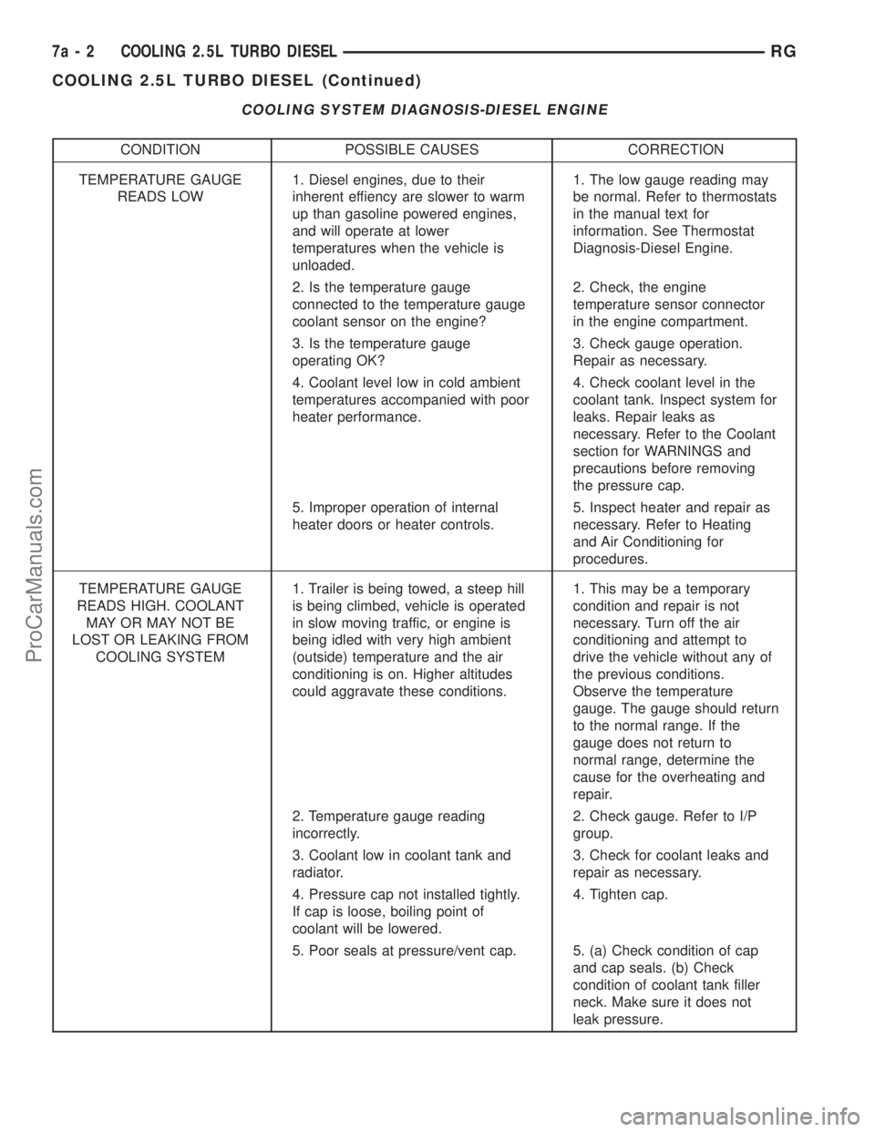
COOLING SYSTEM DIAGNOSIS-DIESEL ENGINE
CONDITION POSSIBLE CAUSES CORRECTION
TEMPERATURE GAUGE
READS LOW1. Diesel engines, due to their
inherent effiency are slower to warm
up than gasoline powered engines,
and will operate at lower
temperatures when the vehicle is
unloaded.1. The low gauge reading may
be normal. Refer to thermostats
in the manual text for
information. See Thermostat
Diagnosis-Diesel Engine.
2. Is the temperature gauge
connected to the temperature gauge
coolant sensor on the engine?2. Check, the engine
temperature sensor connector
in the engine compartment.
3. Is the temperature gauge
operating OK?3. Check gauge operation.
Repair as necessary.
4. Coolant level low in cold ambient
temperatures accompanied with poor
heater performance.4. Check coolant level in the
coolant tank. Inspect system for
leaks. Repair leaks as
necessary. Refer to the Coolant
section for WARNINGS and
precautions before removing
the pressure cap.
5. Improper operation of internal
heater doors or heater controls.5. Inspect heater and repair as
necessary. Refer to Heating
and Air Conditioning for
procedures.
TEMPERATURE GAUGE
READS HIGH. COOLANT
MAY OR MAY NOT BE
LOST OR LEAKING FROM
COOLING SYSTEM1. Trailer is being towed, a steep hill
is being climbed, vehicle is operated
in slow moving traffic, or engine is
being idled with very high ambient
(outside) temperature and the air
conditioning is on. Higher altitudes
could aggravate these conditions.1. This may be a temporary
condition and repair is not
necessary. Turn off the air
conditioning and attempt to
drive the vehicle without any of
the previous conditions.
Observe the temperature
gauge. The gauge should return
to the normal range. If the
gauge does not return to
normal range, determine the
cause for the overheating and
repair.
2. Temperature gauge reading
incorrectly.2. Check gauge. Refer to I/P
group.
3. Coolant low in coolant tank and
radiator.3. Check for coolant leaks and
repair as necessary.
4. Pressure cap not installed tightly.
If cap is loose, boiling point of
coolant will be lowered.4. Tighten cap.
5. Poor seals at pressure/vent cap. 5. (a) Check condition of cap
and cap seals. (b) Check
condition of coolant tank filler
neck. Make sure it does not
leak pressure.
7a - 2 COOLING 2.5L TURBO DIESELRG
COOLING 2.5L TURBO DIESEL (Continued)
ProCarManuals.com
Page 295 of 2399
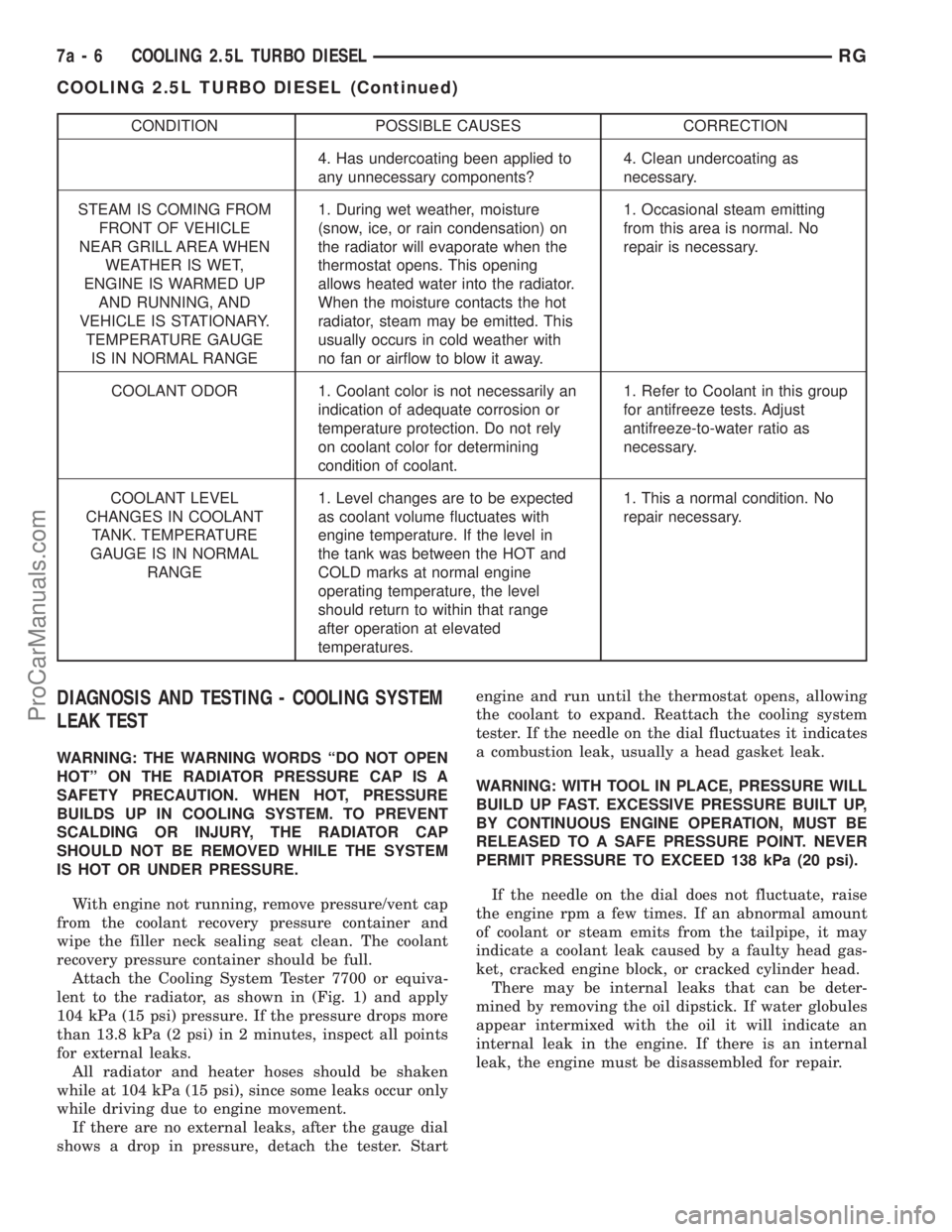
CONDITION POSSIBLE CAUSES CORRECTION
4. Has undercoating been applied to
any unnecessary components?4. Clean undercoating as
necessary.
STEAM IS COMING FROM
FRONT OF VEHICLE
NEAR GRILL AREA WHEN
WEATHER IS WET,
ENGINE IS WARMED UP
AND RUNNING, AND
VEHICLE IS STATIONARY.
TEMPERATURE GAUGE
IS IN NORMAL RANGE1. During wet weather, moisture
(snow, ice, or rain condensation) on
the radiator will evaporate when the
thermostat opens. This opening
allows heated water into the radiator.
When the moisture contacts the hot
radiator, steam may be emitted. This
usually occurs in cold weather with
no fan or airflow to blow it away.1. Occasional steam emitting
from this area is normal. No
repair is necessary.
COOLANT ODOR 1. Coolant color is not necessarily an
indication of adequate corrosion or
temperature protection. Do not rely
on coolant color for determining
condition of coolant.1. Refer to Coolant in this group
for antifreeze tests. Adjust
antifreeze-to-water ratio as
necessary.
COOLANT LEVEL
CHANGES IN COOLANT
TANK. TEMPERATURE
GAUGE IS IN NORMAL
RANGE1. Level changes are to be expected
as coolant volume fluctuates with
engine temperature. If the level in
the tank was between the HOT and
COLD marks at normal engine
operating temperature, the level
should return to within that range
after operation at elevated
temperatures.1. This a normal condition. No
repair necessary.
DIAGNOSIS AND TESTING - COOLING SYSTEM
LEAK TEST
WARNING: THE WARNING WORDS ªDO NOT OPEN
HOTº ON THE RADIATOR PRESSURE CAP IS A
SAFETY PRECAUTION. WHEN HOT, PRESSURE
BUILDS UP IN COOLING SYSTEM. TO PREVENT
SCALDING OR INJURY, THE RADIATOR CAP
SHOULD NOT BE REMOVED WHILE THE SYSTEM
IS HOT OR UNDER PRESSURE.
With engine not running, remove pressure/vent cap
from the coolant recovery pressure container and
wipe the filler neck sealing seat clean. The coolant
recovery pressure container should be full.
Attach the Cooling System Tester 7700 or equiva-
lent to the radiator, as shown in (Fig. 1) and apply
104 kPa (15 psi) pressure. If the pressure drops more
than 13.8 kPa (2 psi) in 2 minutes, inspect all points
for external leaks.
All radiator and heater hoses should be shaken
while at 104 kPa (15 psi), since some leaks occur only
while driving due to engine movement.
If there are no external leaks, after the gauge dial
shows a drop in pressure, detach the tester. Startengine and run until the thermostat opens, allowing
the coolant to expand. Reattach the cooling system
tester. If the needle on the dial fluctuates it indicates
a combustion leak, usually a head gasket leak.
WARNING: WITH TOOL IN PLACE, PRESSURE WILL
BUILD UP FAST. EXCESSIVE PRESSURE BUILT UP,
BY CONTINUOUS ENGINE OPERATION, MUST BE
RELEASED TO A SAFE PRESSURE POINT. NEVER
PERMIT PRESSURE TO EXCEED 138 kPa (20 psi).
If the needle on the dial does not fluctuate, raise
the engine rpm a few times. If an abnormal amount
of coolant or steam emits from the tailpipe, it may
indicate a coolant leak caused by a faulty head gas-
ket, cracked engine block, or cracked cylinder head.
There may be internal leaks that can be deter-
mined by removing the oil dipstick. If water globules
appear intermixed with the oil it will indicate an
internal leak in the engine. If there is an internal
leak, the engine must be disassembled for repair.
7a - 6 COOLING 2.5L TURBO DIESELRG
COOLING 2.5L TURBO DIESEL (Continued)
ProCarManuals.com