heating CHRYSLER VOYAGER 2002 Service Manual
[x] Cancel search | Manufacturer: CHRYSLER, Model Year: 2002, Model line: VOYAGER, Model: CHRYSLER VOYAGER 2002Pages: 2399, PDF Size: 57.96 MB
Page 1 of 2399
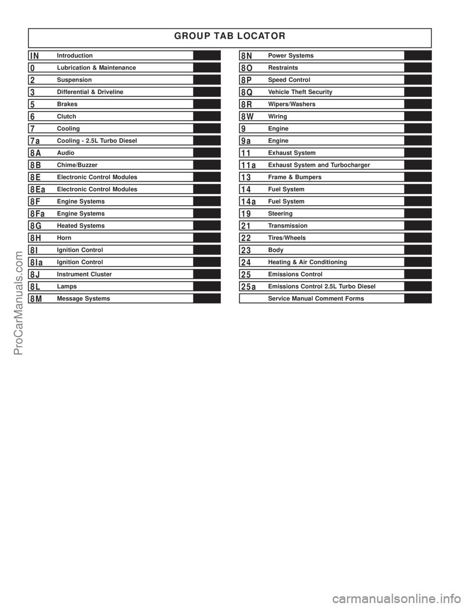
GROUP TAB LOCATOR
INIntroduction
0Lubrication & Maintenance
2Suspension
3Differential & Driveline
5Brakes
6Clutch
7Cooling
7aCooling - 2.5L Turbo Diesel
8AAudio
8BChime/Buzzer
8EElectronic Control Modules
8EaElectronic Control Modules
8FEngine Systems
8FaEngine Systems
8GHeated Systems
8HHorn
8IIgnition Control
8IaIgnition Control
8JInstrument Cluster
8LLamps
8MMessage Systems
8NPower Systems
8ORestraints
8PSpeed Control
8QVehicle Theft Security
8RWipers/Washers
8WWiring
9Engine
9aEngine
11Exhaust System
11aExhaust System and Turbocharger
13Frame & Bumpers
14Fuel System
14aFuel System
19Steering
21Transmission
22Tires/Wheels
23Body
24Heating & Air Conditioning
25Emissions Control
25aEmissions Control 2.5L Turbo Diesel
Service Manual Comment Forms
ProCarManuals.com
Page 17 of 2399
WARNING: Ethanol vapors are extremely flammable
and could cause serious personal injury. Never
have any smoking materials lit in or near the vehi-
cle when removing the fuel filler tube cap (gas cap)
or filling the tank. Do not use E-85 as a cleaning
agent and never use it near an open flame.
FUEL REQUIREMENTS
The vehicle will operate on both unleaded gasoline
with an octane rating of 87, or E-85 fuel, or any mix-
ture of these two.
For best results, a refueling pattern that alternates
between E-85 and unleaded gasoline should be
avoided. When you do switch fuels, it is recom-
mended that
²you do not switch when the fuel gauge indicates
less than 1/4 full
²you do not add less than 5 gallons when refuel-
ing
²you operate the vehicle immediately after refuel-
ing for a period of at least 5 minutes
Observing these precautions will avoid possible
hard starting and/or significant deterioration in
driveability during warm up.
FFV STARTING
The characteristics of E-85 fuel make it unsuitable
for use when ambient temperatures fall below 0ÉF. In
the range of 0ÉF to 32ÉF, you may experience an
increase in the time it takes for your engine to start,
and a deterioration in driveability (sags and/or hesi-
tations) until the engine is fully warmed up.
Engine Operating on E-85 Fuel
If vehicle operates on E-85 fuel either full or part-
time, use only MopartFlexible Fuel 5W-30 engine oil
or an equivalent that meets DaimlerChrysler Stan-
dard MS-9214. Equivalent commercial Flexible Fuel
engine oils may be labeled as Multi-Fuel, Variable
Fuel, Flexible Fuel, etc. These engine oils may be
satisfactory if they meet the DaimlerChrysler Stan-
dard.
SAE 5W-30 engine oil is preferred for use in Flex-
ible Fuel engines.
CAUTION: If Flexible Fuel engine oil is not used
when using E-85 fuel, engine wear or damage may
result.
CRUISING RANGE
Because E-85 fuel contains less energy per gallon
than gasoline, you will experience an increase in fuel
consumption. You can expect your MPG and your
driving range to decrease by about 30% compared to
gasoline operation.
DESCRIPTION - AUTOMATIC TRANSMISSION
FLUID
NOTE: Refer to the maintenance schedules for the
recommended maintenance (fluid/filter change)
intervals for this transaxle.
NOTE: All transaxles have a common transmission
and differential sump. Filling the transaxle accom-
modates the differential as well.
TRANSMISSION FLUID
MopartATF+4 (Automatic Transmission Fluid-
Type 9602) is required in the 41TE automatic and
T850 manual transaxles. Substitute fluids can induce
torque converter clutch shudder.
MopartATF+4 (Automatic Transmission Fluid-
Type 9602) when new is red in color. The ATF is dyed
red so it can be identified from other fluids used in
the vehicle such as engine oil or antifreeze. The red
color is not permanent and is not an indicator of fluid
condition. As the vehicle is driven, the ATF will begin
to look darker in color and may eventually become
brown.This is normal.ATF+4 also has a unique
odor that may change with age. Consequently,odor
and color cannot be used to indicate the fluid
condition or the need for a fluid change.
FLUID ADDITIVES
DaimlerChrysler strongly recommends against the
addition of any fluids to the transmission, other than
those automatic transmission fluids listed above.
Exceptions to this policy are the use of special dyes
to aid in detecting fluid leaks.
Various ªspecialº additives and supplements exist
that claim to improve shift feel and/or quality. These
additives and others also claim to improve converter
clutch operation and inhibit overheating, oxidation,
varnish, and sludge. These claims have not been sup-
ported to the satisfaction of DaimlerChrysler and
these additivesmust not be used.The use of trans-
mission ªsealersº should also be avoided, since they
may adversely affect the integrity of transmission
seals.
DESCRIPTION - FUEL REQUIREMENTS
Your engine is designed to meet all emissions reg-
ulations and provide excellent fuel economy and per-
formance when using high quality unleaded gasoline
having an octane rating of 87. The use of premium
gasoline is not recommended. The use of premium
gasoline will provide no benefit over high quality reg-
ular gasoline, and in some circumstances may result
in poorer performance.
0 - 4 LUBRICATION & MAINTENANCERS
FLUID TYPES (Continued)
ProCarManuals.com
Page 75 of 2399

ment settings to the vehicle specifications for camber,
caster and toe-in. (Refer to 2 - SUSPENSION/
WHEEL ALIGNMENT - SPECIFICATIONS)
(4) If front camber and caster are not within spec-
ifications, proceed to CAMBER AND CASTER below.
If caster and camber are within specifications, pro-
ceed to TOE which can be found following CAMBER
AND CASTER. Rear camber, caster and toe are not
adjustable. If found not to be within specifications,
reinspect for damaged suspension or body compo-
nents and replace as necessary.
CAMBER AND CASTER
Camber and caster settings on this vehicle are
determined at the time the vehicle is designed, by
the location of the vehicle's suspension components.
This is referred to as NET BUILD. The result is no
required adjustment of camber and caster after the
vehicle is built or when servicing the suspension
components. Thus, when performing a wheel align-
ment, caster and camber are not normally considered
adjustable angles. Camber and caster should be
checked to ensure they meet vehicle specifications.
If front camber is found not to meet alignment
specifications, it can be adjusted using an available
camber adjustment bolt package. Before installing a
camber adjustment bolt package on a vehicle found
to be outside the specifications, inspect the suspen-
sion components for any signs of damage or bending.
CAUTION: Do not attempt to adjust the vehicles
wheel alignment by heating, bending or by perform-
ing any other modification to the vehicle's front
suspension components or body.
If camber readings are not within specifications,
use the following procedure to install the front cam-
ber adjustment bolt package and then adjust front
camber.
CAMBER ADJUSTMENT BOLT PACKAGE INSTALLATION
The camber adjustment bolt package contains 2
flange bolts, 2 cam bolts, 2 dog bone washers, and 4
nuts. This package services both sides of the vehicle.
Use the package to attach the strut clevis bracket to
the steering knuckle after the strut clevis bracket
has been modified. To install and adjust the camber
adjustment bolt package, follow the procedure below.
(1) Raise the vehicle until its tires are not support-
ing the weight of the vehicle.
(2) Remove the front tire and wheel assemblies.
CAUTION: When removing the steering knuckle
from the strut clevis bracket, do not put a strain on
the brake flex hose. Also, do not let the weight of
the steering knuckle assembly be supported by the
brake flex hose when removed from the strutassembly. If necessary use a wire hanger to sup-
port the steering knuckle assembly or if required
remove the brake flex hose from the caliper assem-
bly.
CAUTION: The knuckle to strut assembly attaching
bolt shanks are serrated and must not be turned
during removal. Remove the nuts while holding the
bolts stationary.
(3) Remove the top and bottom, strut clevis
bracket to steering knuckle attaching bolts (Fig.
7)and discard. Separate the steering knuckle from
the strut clevis bracket and position steering knuckle
so it is out of the way of the strut.
CAUTION: When slotting the bottom mounting hole
on the strut clevis bracket, do not enlarge the hole
beyond the indentations on the sides of the strut
clevis bracket (Fig. 8).
(4) Using an appropriate grinder and grinding
wheel, slot the bottom hole in both sides of the strut
clevis bracket (Fig. 8).
CAUTION: After slotting the strut clevis bracket
hole, do not install the original attaching bolts when
assembling the steering knuckle to the strut assem-
bly. Only the flange bolts, cam bolts, and dog bone
washers from the service package must be used to
attach the steering knuckle to the strut after the
mounting hole is slotted.
Fig. 7 Clevis Bracket To Steering Knuckle Attaching
Bolts
1 - STRUT CLEVIS BRACKET
2 - ATTACHING BOLTS
3 - TIE ROD END
4 - ROTOR
5 - STEERING KNUCKLE
2 - 52 WHEEL ALIGNMENTRS
WHEEL ALIGNMENT (Continued)
ProCarManuals.com
Page 115 of 2399
BI-DIRECTIONAL
OVERRUNNING CLUTCH
DESCRIPTION
The bi-directional overrunning clutch (BOC) (Fig.
28) works as a mechanical disconnect between the
front and rear axles, preventing torque from being
transferred from the rear axle to the front. The BOC
is a simply an overrunning clutch which works in
both clockwise and counter-clockwise rotations. This
means that when the output (the rear axle) is rotat-
ing faster in one direction than the input (front axle),
there is no torque transmission. But when the input
speed is equal to the output speed, the unit becomes
locked. The BOC provides significant benefits regard-
ing braking stability, handling, and driveline durabil-
ity. Disconnecting the front and the rear driveline
during braking helps to maintain the braking stabil-
ity of an AWD vehicle. In an ABS/braking event, the
locking of the rear wheels must be avoided for stabil-
ity reasons. Therefore brake systems are designed to
lock the front wheels first. Any torque transfer from
the rear axle to the front axle disturbs the ABS/brak-
ing system and causes potential instabilities on aslippery surface. The BOC de-couples the rear driv-
eline as soon the rear wheels begin to spin faster
than the front wheels (front wheels locked) in order
to provide increased braking stability. Furthermore
the BOC also reduces the likelihood of throttle off
over-steer during cornering. In a throttle off maneu-
ver, the BOC once again de-couples the rear driveline
forcing all the engine brake torque to the front
wheels. This eliminates the chance of lateral slip on
the rear axle and increases it on the front. The vehi-
cle will therefore tend to understeer, a situation
which is considered easier to manage in most circum-
stances. During this maneuver, and during the ABS
braking event, the BOC does not transmit torque
through to the rear wheels. The rear driveline mod-
ule, with the BOC, will perform the same as a front
wheel drive vehicle during these events. The gear
ratio offset between the front and rear differentials
force the BOC into the overrunning mode most of the
time. This allows BOC to significantly reduce the
rolling resistance of the vehicle, which improves fuel
consumption, allows the downsizing of the driveline
components, and prevents the PTU and propshaft
joints from overheating.
3 - 36 REAR DRIVELINE MODULERS
ProCarManuals.com
Page 176 of 2399
(27) Install lower steering column cover/knee
blocker (Fig. 62).
(28) Install silencer panel below lower steering col-
umn cover/knee blocker.
NOTE: When reconnecting the battery on a vehicle
that has had the airbag module removed, the fol-
lowing procedure should be used.
(29) Reconnect ground cable to negative post of
battery in following manor:
(a) Connect scan tool (DRBIIIt) to data link
diagnostic connector located below steering column.
(b) Turn ignition key to ON position. Exit vehi-
cle with scan tool leaving scan tool harness
plugged in.
(c) Ensuring that there are no occupants in vehi-
cle, connect ground (-) cable to the negative post of
the battery.
(d) Using scan tool, read and record any airbag
fault codes. Refer to Appropriate Diagnostic Infor-
mation if any faults are found.
(e) Through drivers open window, Reach around
back of steering wheel (between steering wheel and
instrument cluster) and turn ignition key to OFF,
then back ON while observing instrument cluster
airbag indicator lamp. It should go on for six to
eight seconds, then go out. This action indicates
that airbag system is functioning normally. If air-
bag indicator lamp fails to light, blinks on and off,
or goes on and stays on, there is an airbag system
malfunction. Refer to Appropriate Diagnostic Infor-
mation to diagnose the system malfunction.
(30) Using scan tool (DRBIIIt), check for and clear
any existing adjustable pedal fault codes. The adjust-
able pedal system is now activated.
(31) Turn key to OFF and remove scan tool from
vehicle.
(32) Test operation of adjustable pedals, memory
seats (if equipped), RKE (if equipped), and all func-
tions that are steering column operated. If applica-
ble, reset the radio and the clock.
(33) Road test the vehicle to ensure proper opera-
tion of the steering and brake systems.
PEDAL TORQUE SHAFT - RHD
REMOVAL
(1) Remove the instrument panel. (Refer to 23 -
BODY/INSTRUMENT PANEL/INSTRUMENT
PANEL ASSEMBLY - REMOVAL)
(2) Remove the HVAC housing. (Refer to 24 -
HEATING & AIR CONDITIONING/DISTRIBUTION/
HVAC HOUSING - REMOVAL)
(3) Remove the retaining clip at the torque shaft
end of the brake pedal-to-torque shaft link. Removethe link from the torque shaft. Discard the retaining
clip. It is not to be reused. Replace with a new clip
when reassembled.
(4) Locate the booster input rod-to-brake pedal
torque shaft connection and remove the retaining clip
(Fig. 73). Discard the retaining clip. It is not to be
reused. Replace with a new clip when reassembled.
(5) Remove the four (4) brake booster retaining
nuts from inside the passenger compartment (Fig.
74).
(6) Remove the retaining nut from the brake
booster bracket located above the booster in the
engine compartment (Fig. 74).
(7) Remove the power brake booster bracket.
(8) Rotate the pedal torque shaft and remove it out
the left side of the vehicle.
INSTALLATION
(1) Lubricate both ends of the torque shaft with
MS-4517 Lubricant or equivalent and install the
torque shaft from the left side reversing the removal
procedure.
(2) Install the brake booster bracket on the left
end of the shaft.
(3) Install the four brake booster retaining nuts
inside the passenger compartment. Tighten the
mounting nuts to a torque of 29 N´m (250 in. lbs.).
(4) Install the retaining nut for the brake booster
bracket in the engine compartment. Tighten the
mounting nuts to a torque of 29 N´m (250 in. lbs.).
(5) Using lubriplate, or equivalent, coat the sur-
face of the brake pedal torque shaft pin where it con-
tacts the booster input rod. Also coat the surface of
Fig. 73 POWER BRAKE BOOSTER BRACKET
1 - BOOSTER BRACKET
2 - PEDAL TORQUE SHAFT
3 - RETAINING CLIP
4 - BOOSTER MOUNTING NUTS
RSBRAKES - BASE5-47
PEDAL - ADJUSTABLE (Continued)
ProCarManuals.com
Page 239 of 2399
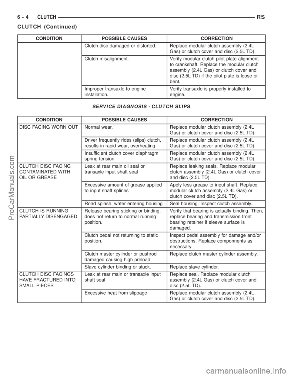
CONDITION POSSIBLE CAUSES CORRECTION
Clutch disc damaged or distorted. Replace modular clutch assembly (2.4L
Gas) or clutch cover and disc (2.5L TD).
Clutch misalignment. Verify modular clutch pilot plate alignment
to crankshaft. Replace the modular clutch
assembly (2.4L Gas) or clutch cover and
disc (2.5L TD) if the pilot plate is loose or
bent.
Improper transaxle-to-engine
installation.Verify transaxle is properly installed to
engine.
SERVICE DIAGNOSIS - CLUTCH SLIPS
CONDITION POSSIBLE CAUSES CORRECTION
DISC FACING WORN OUT Normal wear. Replace modular clutch assembly (2.4L
Gas) or clutch cover and disc (2.5L TD).
Driver frequently rides (slips) clutch,
results in rapid wear, overheating.Replace modular clutch assembly (2.4L
Gas) or clutch cover and disc (2.5L TD).
Insufficient clutch cover diaphragm
spring tensionReplace modular clutch assembly (2.4L
Gas) or clutch cover and disc (2.5L TD).
CLUTCH DISC FACING
CONTAMINATED WITH
OIL OR GREASELeak at rear main oil seal or
transaxle input shaft sealReplace leaking seals. Replace modular
clutch assembly (2.4L Gas) or clutch cover
and disc (2.5L TD).
Excessive amount of grease applied
to input shaft splinesApply less grease to input shaft. Replace
modular clutch assembly (2.4L Gas) or
clutch cover and disc (2.5L TD).
Road splash, water entering housing Seal housing. Inspect clutch assembly.
CLUTCH IS RUNNING
PARTIALLY DISENGAGEDRelease bearing sticking or binding,
does not return to normal running
position.Verify that bearing is actually binding. Then,
replace bearing and transmission front
bearing retainer if sleeve surface is
damaged.
Clutch pedal not returning to static
position.Inspect pedal assembly for damage and/or
obstructions. Replace componnents as
necessary.
Clutch master cylinder or pushrod
damaged causing high preload.Replace clutch master cylinder assembly.
Slave cylinder binding or stuck. Replace slave cylinder.
CLUTCH DISC FACINGS
HAVE FRACTURED INTO
SMALL PIECESLeak at rear main or transaxle input
shaft sealReplace seal. Replace modular clutch
assembly (2.4L Gas) or clutch cover and
disc (2.5L TD)..
Excessive heat from slippage Replace modular clutch assembly (2.4L
Gas) or clutch cover and disc (2.5L TD).
6 - 4 CLUTCHRS
CLUTCH (Continued)
ProCarManuals.com
Page 243 of 2399
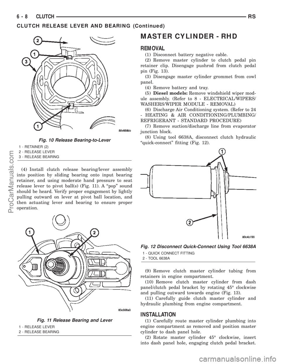
(4) Install clutch release bearing/lever assembly
into position by sliding bearing onto input bearing
retainer, and using moderate hand pressure to seat
release lever to pivot ball(s) (Fig. 11). A ªpopº sound
should be heard. Verify proper engagement by lightly
pulling outward on lever at pivot ball location, and
then actuating lever and bearing to ensure proper
operation.
MASTER CYLINDER - RHD
REMOVAL
(1) Disconnect battery negative cable.
(2) Remove master cylinder to clutch pedal pin
retainer clip. Disengage pushrod from clutch pedal
pin (Fig. 13).
(3) Disengage master cylinder grommet from cowl
panel.
(4) Remove battery and tray.
(5)Diesel models:Remove windshield wiper mod-
ule assembly. (Refer to 8 - ELECTRICAL/WIPERS/
WASHERS/WIPER MODULE - REMOVAL)
(6) Discharge Air Conditioning system. (Refer to 24
- HEATING & AIR CONDITIONING/PLUMBING/
REFRIGERANT - STANDARD PROCEDURE)
(7) Remove suction/discharge line from evaporator
junction block.
(8) Using tool 6638A, disconnect clutch hydraulic
ªquick-connectº fitting (Fig. 12).
(9) Remove clutch master cylinder tubing from
retainers in engine compartment.
(10) Remove clutch master cylinder from dash
panel/clutch pedal bracket by rotating 45É clockwise
and pulling outward towards engine (Fig. 13).
(11) Carefully guide clutch master cylinder and
hydraulic plumbing from engine compartment.
INSTALLATION
(1) Carefully route master cylinder plumbing into
engine compartment as removed and position master
cylinder to dash panel hole.
(2) Rotate master cylinder 45É clockwise, insert
into dash panel hole, engaging clutch pedal bracket.
Fig. 10 Release Bearing-to-Lever
1 - RETAINER (2)
2 - RELEASE LEVER
3 - RELEASE BEARING
Fig. 11 Release Bearing and Lever
1 - RELEASE LEVER
2 - RELEASE BEARING
Fig. 12 Disconnect Quick-Connect Using Tool 6638A
1 - QUICK CONNECT FITTING
2 - TOOL 6638A
6 - 8 CLUTCHRS
CLUTCH RELEASE LEVER AND BEARING (Continued)
ProCarManuals.com
Page 244 of 2399

Rotate master cylinder 45É counter-clockwise, secur-
ing it to pedal bracket (Fig. 13).
(3) Install and secure grommet to dash panel.
(4) Connect pushrod to clutch pedal pin. Install
retainer clip (Fig. 13).
(5) Secure master cylinder plumbing to retainers
in engine compartment.
(6) Connect clutch master cylinder plumbing to
slave cylinder ªquick connectº fitting. An audible
ªclickº should be heard. Verify connection by pulling
outward.
(7) Connect A/C suction/discharge line to evapora-
tor junction block.
(8)Diesel models:Install wiper module assembly.
(Refer to 8 - ELECTRICAL/WIPERS/WASHERS/
WIPER MODULE - INSTALLATION)
(9) Install battery and tray.
(10) Connect battery negative cable
(11) Charge Air Conditioning system. (Refer to 24 -
HEATING & AIR CONDITIONING/PLUMBING/RE-
FRIGERANT - STANDARD PROCEDURE)
MASTER CYLINDER - LHD
REMOVAL
(1) Disconnect battery cables.
(2) Remove instrument panel lower silencer (Fig.
14).
(3) Remove knee bolster (Fig. 15).
Fig. 13 Clutch Master Cylinder at Pedal Bracket
1 - CLUTCH MASTER CYLINDER
2 - RETAINER CLIP
3 - CLUTCH PEDAL PIN
4 - PUSH RODFig. 14 Instrument Panel Lower Silencer
1 - INSTRUMENT PANEL LOWER SILENCER
Fig. 15 Knee Bolster
1 - KNEE BOLSTER
RSCLUTCH6-9
MASTER CYLINDER - RHD (Continued)
ProCarManuals.com
Page 264 of 2399
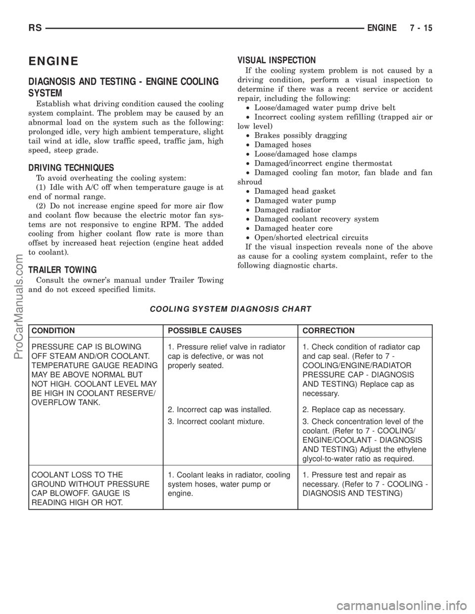
ENGINE
DIAGNOSIS AND TESTING - ENGINE COOLING
SYSTEM
Establish what driving condition caused the cooling
system complaint. The problem may be caused by an
abnormal load on the system such as the following:
prolonged idle, very high ambient temperature, slight
tail wind at idle, slow traffic speed, traffic jam, high
speed, steep grade.
DRIVING TECHNIQUES
To avoid overheating the cooling system:
(1) Idle with A/C off when temperature gauge is at
end of normal range.
(2) Do not increase engine speed for more air flow
and coolant flow because the electric motor fan sys-
tems are not responsive to engine RPM. The added
cooling from higher coolant flow rate is more than
offset by increased heat rejection (engine heat added
to coolant).
TRAILER TOWING
Consult the owner's manual under Trailer Towing
and do not exceed specified limits.
VISUAL INSPECTION
If the cooling system problem is not caused by a
driving condition, perform a visual inspection to
determine if there was a recent service or accident
repair, including the following:
²Loose/damaged water pump drive belt
²Incorrect cooling system refilling (trapped air or
low level)
²Brakes possibly dragging
²Damaged hoses
²Loose/damaged hose clamps
²Damaged/incorrect engine thermostat
²Damaged cooling fan motor, fan blade and fan
shroud
²Damaged head gasket
²Damaged water pump
²Damaged radiator
²Damaged coolant recovery system
²Damaged heater core
²Open/shorted electrical circuits
If the visual inspection reveals none of the above
as cause for a cooling system complaint, refer to the
following diagnostic charts.
COOLING SYSTEM DIAGNOSIS CHART
CONDITION POSSIBLE CAUSES CORRECTION
PRESSURE CAP IS BLOWING
OFF STEAM AND/OR COOLANT.
TEMPERATURE GAUGE READING
MAY BE ABOVE NORMAL BUT
NOT HIGH. COOLANT LEVEL MAY
BE HIGH IN COOLANT RESERVE/
OVERFLOW TANK.1. Pressure relief valve in radiator
cap is defective, or was not
properly seated.1. Check condition of radiator cap
and cap seal. (Refer to 7 -
COOLING/ENGINE/RADIATOR
PRESSURE CAP - DIAGNOSIS
AND TESTING) Replace cap as
necessary.
2. Incorrect cap was installed. 2. Replace cap as necessary.
3. Incorrect coolant mixture. 3. Check concentration level of the
coolant. (Refer to 7 - COOLING/
ENGINE/COOLANT - DIAGNOSIS
AND TESTING) Adjust the ethylene
glycol-to-water ratio as required.
COOLANT LOSS TO THE
GROUND WITHOUT PRESSURE
CAP BLOWOFF. GAUGE IS
READING HIGH OR HOT.1. Coolant leaks in radiator, cooling
system hoses, water pump or
engine.1. Pressure test and repair as
necessary. (Refer to 7 - COOLING -
DIAGNOSIS AND TESTING)
RSENGINE7-15
ProCarManuals.com
Page 265 of 2399
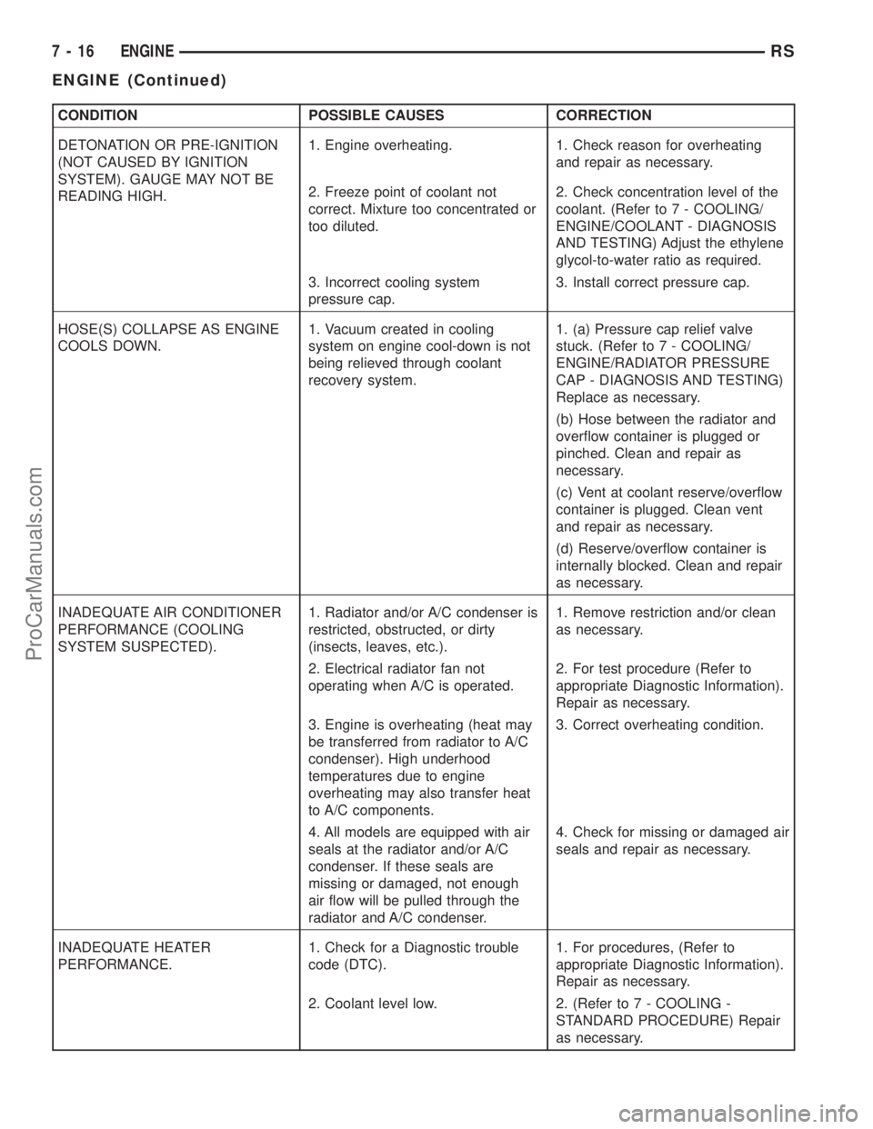
CONDITION POSSIBLE CAUSES CORRECTION
DETONATION OR PRE-IGNITION
(NOT CAUSED BY IGNITION
SYSTEM). GAUGE MAY NOT BE
READING HIGH.1. Engine overheating. 1. Check reason for overheating
and repair as necessary.
2. Freeze point of coolant not
correct. Mixture too concentrated or
too diluted.2. Check concentration level of the
coolant. (Refer to 7 - COOLING/
ENGINE/COOLANT - DIAGNOSIS
AND TESTING) Adjust the ethylene
glycol-to-water ratio as required.
3. Incorrect cooling system
pressure cap.3. Install correct pressure cap.
HOSE(S) COLLAPSE AS ENGINE
COOLS DOWN.1. Vacuum created in cooling
system on engine cool-down is not
being relieved through coolant
recovery system.1. (a) Pressure cap relief valve
stuck. (Refer to 7 - COOLING/
ENGINE/RADIATOR PRESSURE
CAP - DIAGNOSIS AND TESTING)
Replace as necessary.
(b) Hose between the radiator and
overflow container is plugged or
pinched. Clean and repair as
necessary.
(c) Vent at coolant reserve/overflow
container is plugged. Clean vent
and repair as necessary.
(d) Reserve/overflow container is
internally blocked. Clean and repair
as necessary.
INADEQUATE AIR CONDITIONER
PERFORMANCE (COOLING
SYSTEM SUSPECTED).1. Radiator and/or A/C condenser is
restricted, obstructed, or dirty
(insects, leaves, etc.).1. Remove restriction and/or clean
as necessary.
2. Electrical radiator fan not
operating when A/C is operated.2. For test procedure (Refer to
appropriate Diagnostic Information).
Repair as necessary.
3. Engine is overheating (heat may
be transferred from radiator to A/C
condenser). High underhood
temperatures due to engine
overheating may also transfer heat
to A/C components.3. Correct overheating condition.
4. All models are equipped with air
seals at the radiator and/or A/C
condenser. If these seals are
missing or damaged, not enough
air flow will be pulled through the
radiator and A/C condenser.4. Check for missing or damaged air
seals and repair as necessary.
INADEQUATE HEATER
PERFORMANCE.1. Check for a Diagnostic trouble
code (DTC).1. For procedures, (Refer to
appropriate Diagnostic Information).
Repair as necessary.
2. Coolant level low. 2. (Refer to 7 - COOLING -
STANDARD PROCEDURE) Repair
as necessary.
7 - 16 ENGINERS
ENGINE (Continued)
ProCarManuals.com