torque CHRYSLER VOYAGER 2002 Service Manual
[x] Cancel search | Manufacturer: CHRYSLER, Model Year: 2002, Model line: VOYAGER, Model: CHRYSLER VOYAGER 2002Pages: 2399, PDF Size: 57.96 MB
Page 2074 of 2399

(1) Remove head rest sleeves. (Refer to 23 - BODY/
SEATS/HEADREST SLEEVE - REMOVAL)
(2) Remove the armrest. (Refer to 23 - BODY/
SEATS/ARMREST - REMOVAL)
(3) Remove the seatback recliner lever.
(4) Remove the lumbar adjustment lever.
(5) Remove both seat cushion side covers. (Refer to
23 - BODY/SEATS/FRONT SEAT CUSHION SIDE
COVER - REMOVAL)
(6) Remove nut attaching the recliner to the seat-
back frame (Fig. 15).
(7) Remove both pivot bolts and remove seatback
from recliner.
INSTALLATION
(1) Place seat back into position.
(2) Install both pivot bolts attaching seat back
frame to seat track. Tighten bolts to 54 N´m (40 ft.
lbs.) torque.
(3) Install nut attaching the recliner to the seat
back frame. Tighten nut to 12 N´m (105 in. lbs.)
torque.
(4) Install both seat cushion side covers. (Refer to
23 - BODY/SEATS/FRONT SEAT CUSHION SIDE
COVER - INSTALLATION)
(5) Install the lumbar adjustment lever.
(6) Install the seat back recliner lever.
(7) Install the armrest. (Refer to 23 - BODY/
SEATS/ARMREST - INSTALLATION)
(8) Install headrest sleeves. (Refer to 23 - BODY/
SEATS/HEADREST SLEEVE - INSTALLATION)
FRONT SEATBACK ASSIST
STRAP
REMOVAL
(1) Using a small screw driver, pry screw plugs
from ends of assist strap (Fig. 16).
(2) Remove screws attaching assist strap to seat-
back.
(3) Remove assist strap from vehicle.
Fig. 14 FRONT SEAT
1 - FRONT SEAT
2 - CONNECTORS
3 - B-PILLAR
Fig. 15 FRONT SEATBACK
Fig. 16 FRONT SEATBACK ASSIST STRAP
1 - ASSIST STRAP
2 - SCREW PLUG
3 - SEAT BACK
RSSEATS23-91
FRONT SEATBACK (Continued)
ProCarManuals.com
Page 2076 of 2399

(4) If equipped, open stowage bin to access front
pan bolts.
(5) Remove bolts attaching seat cushion pan to
seat track.
(6) Disconnect wire connectors, if equipment.
(7) Remove seat cushion from seat.
(8) Disengage J-strap retainers holding seat cover
to cushion.
(9) Remove seat cushion pan from cover and pad.
INSTALLATION
(1) Place seat cushion cover in position on seat
cushion.
(2) Engage J-strap retainers to hold seat cover to
cushion.
(3) Place seat cushion in position on seat.
(4) Connect wire connectors, if equipment.
(5) Install bolts attaching seat cushion to seat
track. Tighten bolts to 28.5 N´m (21 ft. lbs.) torque.
(6) If equipped, close stowage bin.
(7) Install seat track front and rear covers, if
equipped. (Refer to 23 - BODY/SEATS/SEAT TRACK
REAR COVER - INSTALLATION) and (Refer to 23 -
BODY/SEATS/SEAT TRACK FRONT COVER -
INSTALLATION)
(8) Install the quad seat side shield and cup holder
if equipped. (Refer to 23 - BODY/SEATS/QUAD
BUCKET SEAT SIDE SHIELD/CUP HOLDER -
INSTALLATION) and (Refer to 23 - BODY/SEATS/
QUAD BUCKET SEAT SIDE SHIELD - NO CUP
HOLDER - INSTALLATION)
(9) Install seat cushion side covers. (Refer to 23 -
BODY/SEATS/FRONT SEAT CUSHION SIDE
COVER - INSTALLATION)
FRONT SEAT CUSHION SIDE
COVER
REMOVAL
(1) Remove screws and plastic push pin attaching
seat cushion side cover to bucket seat (Fig. 18).
(2) Disengage J-strap along rear of seat cushion to
access screw.
(3) Remove screw attaching rear of side cover to
seat cushion frame.
(4) Remove side cover from seat cushion.
(5) If equipped, disconnect wire connector from
power seat switch (Fig. 19).
INSTALLATION
(1) Place side cover in position on seat cushion.
(2) If equipped, connect wire connector into power
seat switch.
(3) Install screw attaching rear of side cover to
seat cushion frame. Tighten screw to 1 N´m (9 in.
lbs.) torque.
(4) Engage J-strap along rear of seat cushion to
access screw.
(5) Install screws attaching seat cushion side cover
to bucket seat (Fig. 18).
Fig. 18 FRONT SEAT SIDE SHIELD
1 - SCREWS
2 - SIDE SHIELD
3 - SEAT CUSHION
Fig. 19 POWER SEAT SWITCH WIRE CONNECTOR
1 - SEAT CUSHION SIDE COVER
2 - POWER SEAT SWITCH
3 - WIRE CONNECTOR
RSSEATS23-93
FRONT/QUAD SEAT CUSHION (Continued)
ProCarManuals.com
Page 2077 of 2399

FRONT SEAT RISER - MANUAL
TRACK
REMOVAL
(1) Remove seat from vehicle. (Refer to 23 - BODY/
SEATS/FRONT SEAT - REMOVAL)
(2) Remove storage bin from riser. (Refer to 23 -
BODY/SEATS/UNDER SEAT STORAGE BIN -
REMOVAL)
(3) Remove nuts attaching riser to manual seat
track (Fig. 20).
(4) Remove riser from seat.
INSTALLATION
(1) Place riser in position on seat.
(2) Install nuts attaching riser to manual seat
track (Fig. 20). Tighten fasteners to 81 N´m (60 ft.
lbs.) torque.
(3) If equipped, install storage bin into riser. (Refer
to 23 - BODY/SEATS/UNDER SEAT STORAGE BIN
- INSTALLATION)
(4) Install seat into vehicle. Tighten fasteners to
54 N´m (40 ft. lbs.) torque. (Refer to 23 - BODY/
SEATS/FRONT SEAT - INSTALLATION)
FRONT SEAT TRACK POWER
ADJUSTER
REMOVAL
The power seat track and motors are serviced as
an assembly.
(1) Remove seat from vehicle. (Refer to 23 - BODY/
SEATS/FRONT SEAT - REMOVAL)
(2) Remove seat cushion. (Refer to 23 - BODY/
SEATS/FRONT/QUAD SEAT CUSHION -
REMOVAL)
(3) Remove nut attaching recliner to seat back
frame.
(4) Remove bolts attaching seat back frame to seat
track.
(5) Remove stud on seat back frame from recliner.
(6) Remove seat back.
(7) If power seat track is being replaced, transfer
power recliner, wire harness and trim covers to
replacement seat track.
INSTALLATION
The power seat track and motors are serviced as
an assembly.
(1) Install wire harness.
(2) Place seat back in position.
(3) Insert stud on seat back frame into recliner.
(4) Install bolts to hold seat back frame to seat
track.
(5) Install nut attaching recliner to seat back
frame.
(6) Install seat cushion. (Refer to 23 - BODY/
SEATS/FRONT/QUAD SEAT CUSHION - INSTAL-
LATION)
(7) Install seat in vehicle. Tighten fasteners to 60
N´m (44 ft. lbs.) torque. (Refer to 23 - BODY/SEATS/
FRONT SEAT - INSTALLATION)
FRONT SEAT TRACK MANUAL
ADJUSTER
REMOVAL
(1) Remove seat from vehicle. (Refer to 23 - BODY/
SEATS/FRONT SEAT - REMOVAL)
(2) Remove seat cushion. (Refer to 23 - BODY/
SEATS/FRONT/QUAD SEAT CUSHION -
REMOVAL)
(3) Remove riser. (Refer to 23 - BODY/SEATS/
FRONT SEAT RISER - MANUAL TRACK -
REMOVAL)
Fig. 20 FRONT SEAT RISER - MANUAL TRACK
1 - RISER
2 - SEAT TRACK
23 - 94 SEATSRS
ProCarManuals.com
Page 2078 of 2399

(4) Remove bolt attaching seat back frame to seat
track (Fig. 21).
(5) Remove seat track from seat adjuster handle
(Fig. 22).
(6) Remove seat track from seat.INSTALLATION
(1) Place seat track in position on seat.
(2) Place adjuster handle in position on seat track
(Fig. 22).
(3) Insert stud on seat back frame into recliner.
(4) Install bolt attaching seat back frame to seat
track (Fig. 21).
(5) Install riser. (Refer to 23 - BODY/SEATS/
FRONT SEAT RISER - MANUAL TRACK - INSTAL-
LATION)
(6) Install seat cushion. (Refer to 23 - BODY/
SEATS/FRONT/QUAD SEAT CUSHION - INSTAL-
LATION)
(7) Install seat in vehicle. (Refer to 23 - BODY/
SEATS/FRONT SEAT - INSTALLATION)
FRONT SEAT TRACK - FRONT
COVER
REMOVAL
(1) Remove screws attaching front cover to seat
track (Fig. 23).
(2) Remove front cover from vehicle.
INSTALLATION
(1) Place front cover in position on seat.
(2) Install screws attaching front cover to seat
track (Fig. 23). Tighten screws to 4 N´m (35 in. lbs.)
torque.
Fig. 21 FRONT SEAT TRACK - MANUAL
1 - SHOULDER BOLT
2 - RECLINER
3 - MANUAL SEAT TRACK
Fig. 22 FRONT SEAT TRACK ADJUSTER HANDLE
1 - RECLINER
2 - SEAT ADJUSTER HANDLE
3 - MANUAL SEAT TRACK
Fig. 23 FRONT SEAT TRACK FRONT COVER -
MANUAL DRIVERS SEAT
1 - SCREWS
2 - COVER
3 - SEAT CUSHION
RSSEATS23-95
FRONT SEAT TRACK MANUAL ADJUSTER (Continued)
ProCarManuals.com
Page 2081 of 2399

(3) Install the seat side shield/cup holder. (Refer to
23 - BODY/SEATS/QUAD BUCKET SEAT SIDE
SHIELD/CUP HOLDER - INSTALLATION)
(4) Install the seat. Refer to Owner's Manual for
proper procedures.
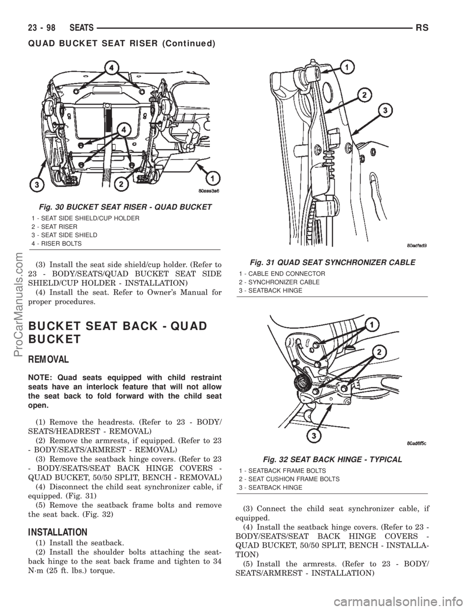
BUCKET SEAT BACK - QUAD
BUCKET
REMOVAL
NOTE: Quad seats equipped with child restraint
seats have an interlock feature that will not allow
the seat back to fold forward with the child seat
open.
(1) Remove the headrests. (Refer to 23 - BODY/
SEATS/HEADREST - REMOVAL)
(2) Remove the armrests, if equipped. (Refer to 23
- BODY/SEATS/ARMREST - REMOVAL)
(3) Remove the seatback hinge covers. (Refer to 23
- BODY/SEATS/SEAT BACK HINGE COVERS -
QUAD BUCKET, 50/50 SPLIT, BENCH - REMOVAL)
(4) Disconnect the child seat synchronizer cable, if
equipped. (Fig. 31)
(5) Remove the seatback frame bolts and remove
the seat back. (Fig. 32)
INSTALLATION
(1) Install the seatback.
(2) Install the shoulder bolts attaching the seat-
back hinge to the seat back frame and tighten to 34
N´m (25 ft. lbs.) torque.(3) Connect the child seat synchronizer cable, if
equipped.
(4) Install the seatback hinge covers. (Refer to 23 -
BODY/SEATS/SEAT BACK HINGE COVERS -
QUAD BUCKET, 50/50 SPLIT, BENCH - INSTALLA-
TION)
(5) Install the armrests. (Refer to 23 - BODY/
SEATS/ARMREST - INSTALLATION)
Fig. 30 BUCKET SEAT RISER - QUAD BUCKET
1 - SEAT SIDE SHIELD/CUP HOLDER
2 - SEAT RISER
3 - SEAT SIDE SHIELD
4 - RISER BOLTS
Fig. 31 QUAD SEAT SYNCHRONIZER CABLE
1 - CABLE END CONNECTOR
2 - SYNCHRONIZER CABLE
3 - SEATBACK HINGE
Fig. 32 SEAT BACK HINGE - TYPICAL
1 - SEATBACK FRAME BOLTS
2 - SEAT CUSHION FRAME BOLTS
3 - SEATBACK HINGE
23 - 98 SEATSRS
QUAD BUCKET SEAT RISER (Continued)
ProCarManuals.com
Page 2083 of 2399

INSTALLATION
BENCH SEAT & 50/50 SPLIT
(1) Position the seat cushion cover on the cushion.
(2) Engage the J-strap retainers.
(3) Steam wrinkles from seat cushion, if necessary.
(4) Install seat risers. (Refer to 23 - BODY/SEATS/
BENCH SEAT RISER - 50/50 SPLIT - INSTALLA-
TION) and (Refer to 23 - BODY/SEATS/BENCH
SEAT RISER - SECOND ROW - INSTALLATION)
and (Refer to 23 - BODY/SEATS/BENCH SEAT
RISER - THIRD ROW - INSTALLATION)
(5) Install seat back. (Refer to 23 - BODY/SEATS/
BENCH SEAT BACK - INSTALLATION)
(6) Install seat into vehicle.
QUAD BUCKET
(1) Position the seat cushion cover on the cushion.
(2) Engage the J-strap retainers.
(3) Steam wrinkles from seat cushion, if necessary.
(4) Install seat risers. (Refer to 23 - BODY/SEATS/
QUAD BUCKET SEAT RISER - INSTALLATION)
(5) Install seat back. (Refer to 23 - BODY/SEATS/
BUCKET SEAT BACK - QUAD BUCKET - INSTAL-
LATION)
(6) Install seat into vehicle.
BENCH SEAT RISER - 50/50
SPLIT
REMOVAL
(1) Remove the seat from the vehicle. Refer to the
Owners Manual for proper procedures.
(2) Unclip the seat cushion cover j-strap. (Fig. 35).
(3) Remove the six bolts and remove the riser.
INSTALLATION
(1) Place the riser onto the seat install the bolts
and tighten to 48 N´m (35 ft. lbs.) torque.
(2) Clip seat cusion cover j-strap onto the riser.
(3) Install the seat into the vehicle. Refer to the
Owner's Manual for proper procedure.
BENCH SEAT RISER - SECOND
ROW
REMOVAL
(1) Remove seat from vehicle. Refer to Owner's
Manual for proper procedures.
(2) Place seat bottom side up on a clean covered
work surface.
(3) Remove bolts attaching seat riser to seat cush-
ion frame (Fig. 36).(4) Remove riser from seat.
Fig. 35 BENCH SEAT RISER - 50/50 SPLIT
1 - SEAT CUSHION COVER CLIP
2 - SEAT RISER BOLTS
3 - SEAT RISER
Fig. 36 BENCH SEAT RISER - SECOND ROW
1 - RISER
2 - FIRST ROW BENCH SEAT
3 - RISER BOLTS
23 - 100 SEATSRS
SEAT CUSHION COVER - QUAD BUCKET, 50/50 SPLIT, BENCH (Continued)
ProCarManuals.com
Page 2084 of 2399

INSTALLATION
(1) Place riser in position on seat.
(2) Install bolts attaching seat riser to seat cush-
ion frame (Fig. 36). Tighten bolts to 48 N´m (35 ft.
lbs.) torque.
(3) Install seat into vehicle.
BENCH SEAT RISER - THIRD
ROW
REMOVAL
(1) Remove seat track. (Refer to 23 - BODY/
SEATS/BENCH SEAT TRACK - REMOVAL)
(2) Remove bolts attaching riser to seat cushion
frame and remove the riser. (Fig. 41).
INSTALLATION
(1) Place riser in position on seat.
(2) Install bolts attaching riser to seat cushion
frame (Fig. 41). Tighten nuts to 48 N´m (35 ft. lbs.)
torque.
(3) Install seat track. (Refer to 23 - BODY/SEATS/
BENCH SEAT TRACK - INSTALLATION)
SEAT BACK HINGE COVERS -
QUAD BUCKET, 50/50 SPLIT,
BENCH
REMOVAL
(1) Remove seat from vehicle. Refer to Owner's
Manual for proper procedures.
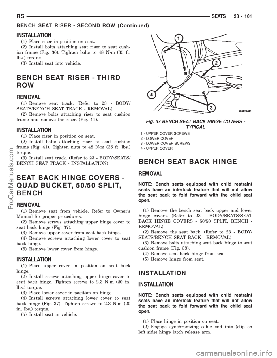
(2) Remove screws attaching upper hinge cover to
seat back hinge (Fig. 37).
(3) Remove upper cover from seat back hinge.
(4) Remove screws attaching lower cover to seat
back hinge.
(5) Remove lower cover from hinge.
INSTALLATION
(1) Place upper cover in position on seat back
hinge.
(2) Install screws attaching upper hinge cover to
seat back hinge. Tighten screws to 2.3 N´m (20 in.
lbs.) torque.
(3) Place lower cover in position on hinge.
(4) Install screws attaching lower cover to seat
back hinge (Fig. 37). Tighten screws to 2.3 N´m (20
in. lbs.) torque.
(5) Install seat in vehicle.
BENCH SEAT BACK HINGE
REMOVAL
NOTE: Bench seats equipped with child restraint
seats have an interlock feature that will not allow
the seat back to fold forward with the child seat
open.
(1) Remove the bench seat back upper and lower
hinge covers. (Refer to 23 - BODY/SEATS/SEAT
BACK HINGE COVERS - 50/50 SPLIT, BENCH -
REMOVAL)
(2) Remove the seat back. (Refer to 23 - BODY/
SEATS/BENCH SEAT BACK - REMOVAL)
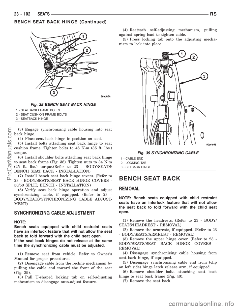
(3) Remove bolts attaching seat back hinge to seat
cushion frame (Fig. 38).
(4) Remove seat back hinge from seat.
(5) Remove hinge from seat.
INSTALLATION
INSTALLATION
NOTE: Bench seats equipped with child restraint
seats have an interlock feature that will not allow
the seat back to fold forward with the child seat
open.
(1) Place hinge in position on seat.
(2) Engage synchronizing cable end into (clip on
left side) hinge latch release arm.
Fig. 37 BENCH SEAT BACK HINGE COVERS -
TYPICAL
1 - UPPER COVER SCREWS
2 - LOWER COVER
3 - LOWER COVER SCREWS
4 - UPPER COVER
RSSEATS23 - 101
BENCH SEAT RISER - SECOND ROW (Continued)
ProCarManuals.com
Page 2085 of 2399

(3) Engage synchronizing cable housing into seat
back hinge.
(4) Place seat back hinge in position on seat.
(5) Install bolts attaching seat back hinge to seat
cushion frame. Tighten bolts to 48 N´m (35 ft. lbs.)
torque.
(6) Install shoulder bolts attaching seat back hinge
to seat back frame (Fig. 38). Tighten nuts to 34 N´m
(25 ft. lbs.) torque.(Refer to 23 - BODY/SEATS/
BENCH SEAT BACK - INSTALLATION)
(7) Install bench seat back hinge covers. (Refer to
23 - BODY/SEATS/SEAT BACK HINGE COVERS -
50/50 SPLIT, BENCH - INSTALLATION)
(8) Verify seat back hinge operation and adjust
synchronizing cable, if equipped. (Refer to 23 -
BODY/SEATS/SYNCHRONIZING CABLE ADJUST-
MENT)
SYNCHRONIZING CABLE ADJUSTMENT
NOTE:
Bench seats equipped with child restraint seats
have an interlock feature that will not allow the seat
back to fold forward with the child seat open.
If the seat back hinges do not release at the same
time the synchronizing cable must be adjusted.
(1) Remove seat from vehicle. Refer to Owner's
Manual for proper procedures.
(2) Disengage cable from the recline mechanism by
pulling the cable end toward the front of the seat
(Fig. 39).
(3) Pull U-shaped locking tab on self-adjusting
mehcanism to disengage auto-adjust feature.(4) Reattach self-adjusting mechanism, pulling
against spring load to tighten cable.
(5) Press locking tab onto the adjusting mecha-
nism to lock into place.
BENCH SEAT BACK
REMOVAL
NOTE: Bench seats equipped with child restraint
seats have an interlock feature that will not allow
the seat back to fold forward with the child seat
open.
(1) Remove the headrests. (Refer to 23 - BODY/
SEATS/HEADREST - REMOVAL)
(2) Remove the armrests, if equipped. (Refer to 23
- BODY/SEATS/ARMREST - REMOVAL)
(3) Remove the upper hinge cover. (Refer to 23 -
BODY/SEATS/SEAT BACK HINGE COVERS -
REMOVAL)
(4) Disengage synchronizing cable housing from
seat back hinge, if equipped.
(5) Disengage synchronizing cable end from (clip
on left side) hinge latch release arm, if equipped.
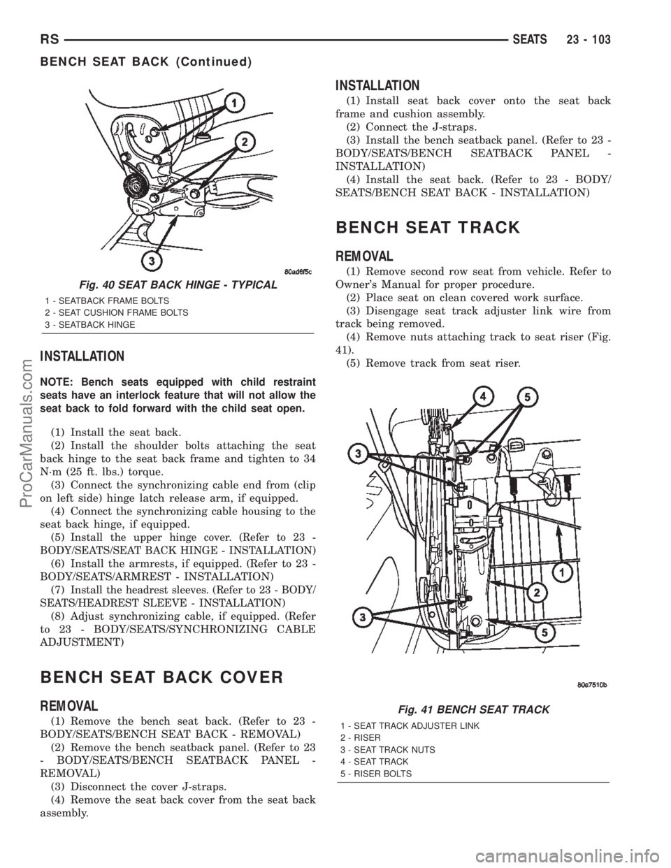
(6) Remove shoulder bolts attaching seat back
hinge to seat back frame (Fig. 40).
(7) Remove the seat back.
Fig. 38 BENCH SEAT BACK HINGE
1 - SEATBACK FRAME BOLTS
2 - SEAT CUSHION FRAME BOLTS
3 - SEATBACK HINGE
Fig. 39 SYNCHRONIZING CABLE
1 - CABLE END
2 - LOCKING TAB
3 - SETBACK HINGE
23 - 102 SEATSRS
BENCH SEAT BACK HINGE (Continued)
ProCarManuals.com
Page 2086 of 2399

INSTALLATION
NOTE: Bench seats equipped with child restraint
seats have an interlock feature that will not allow the
seat back to fold forward with the child seat open.
(1) Install the seat back.
(2) Install the shoulder bolts attaching the seat
back hinge to the seat back frame and tighten to 34
N´m (25 ft. lbs.) torque.
(3) Connect the synchronizing cable end from (clip
on left side) hinge latch release arm, if equipped.
(4) Connect the synchronizing cable housing to the
seat back hinge, if equipped.
(5)
Install the upper hinge cover. (Refer to 23 -
BODY/SEATS/SEAT BACK HINGE - INSTALLATION)
(6) Install the armrests, if equipped. (Refer to 23 -
BODY/SEATS/ARMREST - INSTALLATION)
(7)
Install the headrest sleeves. (Refer to 23 - BODY/
SEATS/HEADREST SLEEVE - INSTALLATION)
(8) Adjust synchronizing cable, if equipped. (Refer
to 23 - BODY/SEATS/SYNCHRONIZING CABLE
ADJUSTMENT)
BENCH SEAT BACK COVER
REMOVAL
(1) Remove the bench seat back. (Refer to 23 -
BODY/SEATS/BENCH SEAT BACK - REMOVAL)
(2) Remove the bench seatback panel. (Refer to 23
- BODY/SEATS/BENCH SEATBACK PANEL -
REMOVAL)
(3) Disconnect the cover J-straps.
(4) Remove the seat back cover from the seat back
assembly.
INSTALLATION
(1) Install seat back cover onto the seat back
frame and cushion assembly.
(2) Connect the J-straps.
(3) Install the bench seatback panel. (Refer to 23 -
BODY/SEATS/BENCH SEATBACK PANEL -
INSTALLATION)
(4) Install the seat back. (Refer to 23 - BODY/
SEATS/BENCH SEAT BACK - INSTALLATION)
BENCH SEAT TRACK
REMOVAL
(1) Remove second row seat from vehicle. Refer to
Owner's Manual for proper procedure.
(2) Place seat on clean covered work surface.
(3) Disengage seat track adjuster link wire from
track being removed.
(4) Remove nuts attaching track to seat riser (Fig.
41).
(5) Remove track from seat riser.
Fig. 40 SEAT BACK HINGE - TYPICAL
1 - SEATBACK FRAME BOLTS
2 - SEAT CUSHION FRAME BOLTS
3 - SEATBACK HINGE
Fig. 41 BENCH SEAT TRACK
1 - SEAT TRACK ADJUSTER LINK
2 - RISER
3 - SEAT TRACK NUTS
4 - SEAT TRACK
5 - RISER BOLTS
RSSEATS23 - 103
BENCH SEAT BACK (Continued)
ProCarManuals.com
Page 2087 of 2399

INSTALLATION
(1) Place track in position on seat riser.
(2) Install nuts attaching track to seat riser. (Fig.
41). Tighten nuts to 48 N´m (35 ft. lbs.) torque.
(3) Engage seat track adjuster link wire onto track
being installed.
(4) Install second row seat into vehicle.
PLASTIC GROCERY BAG
RETAINER
REMOVAL
3-PASS BENCH SEAT
(1) Remove five screws attaching the plastic gro-
cery bag retainer to the steel slats on the back frame
(Fig. 42).
(2) Remove retainer.
50/50 SPLIT BENCH SEAT
(1) Remove the screws. (Fig. 43)
(2) Pull top of retainer away from the seatback
and lift off of the two bottom attachment hooks.
INSTALLATION
3-PASS BENCH SEAT
(1) Place retainer in position.
(2) Install the five attaching screws and tighten 2
N´m (17 in. lbs.) torque.
50/50 SPLIT BENCH SEAT
(1) Engage bottom hooks of the retainer and place
into position.
(2) Install the attaching screws and tighten 2 N´m
(17 in. lbs.) torque.
UNDER SEAT STORAGE BIN
REMOVAL
(1) Release under seat storage bin latch and open
bin.
(2) Depress lock tabs at the rear/top edge of the
storage bin (Fig. 44).
(3) Pull storage bin from bucket seat riser.
Fig. 42 PLASTIC GROCERY BAG RETAINER
1 - SCREWS
2 - SCREWS
Fig. 43 PLASTIC GROCERY BAG RETAINER - 50/50
SPLIT
1 - SEATBACK
2 - SCREWS
3 - SEATBACK PANEL
4 - GROCERY BAG RETAINER
5 - ATTACHMENT HOOKS
Fig. 44 STORAGE BIN
1 - PASS. SIDE BUCKET SEAT
2 - UNDER SEAT STORAGE BIN
3 - RISER
4 - LOCK TAB
23 - 104 SEATSRS
BENCH SEAT TRACK (Continued)
ProCarManuals.com