speed sensor CHRYSLER VOYAGER 2002 Workshop Manual
[x] Cancel search | Manufacturer: CHRYSLER, Model Year: 2002, Model line: VOYAGER, Model: CHRYSLER VOYAGER 2002Pages: 2399, PDF Size: 57.96 MB
Page 368 of 2399
STANDARD PROCEDURE
STANDARD PROCEDURE - PINION FACTOR
SETTING
NOTE: This procedure must be performed if the
Transmission Control Module (TCM) has been
replaced with a NEW or replacement unit. Failure to
perform this procedure will result in an inoperative
or improperly calibrated speedometer.
The vehicle speed readings for the speedometer are
taken from the output speed sensor. The TCM must
be calibrated to the different combinations of equip-
ment (final drive and tires) available. Pinion Factor
allows the technician to set the Transmission Control
Module initial setting so that the speedometer read-
ings will be correct. To properly read and/or reset the
Pinion Factor, it is necessary to use a DRBIIItscan
tool.
(1) Plug the DRBIIItscan tool into the diagnostic
connector located under the instrument panel.
(2) Select the Transmission menu.
(3) Select the Miscellaneous menu.
(4) Select Pinion Factor. Then follow the instruc-
tions on the DRBIIItscan tool screen.
STANDARD PROCEDURE - QUICK LEARN
PROCEDURE
The quick learn procedure requires the use of the
DRBIIItscan tool. This program allows the elec-
tronic transaxle system to recalibrate itself. This will
provide the best possible transaxle operation.
NOTE: The quick learn procedure should be per-
formed if any of the following procedures are per-
formed:
²Transaxle Assembly Replacement
²Transmission Control Module Replacement
²Solenoid/Pressure Switch Assembly Replacement
²Clutch Plate and/or Seal Replacement
²Valve Body Replacement or Recondition
To perform the Quick Learn Procedure, the follow-
ing conditions must be met:
²The brakes must be applied
²The engine speed must be above 500 rpm
²The throttle angle (TPS) must be less than 3
degrees
²The shift lever position must stay until
prompted to shift to overdrive
²The shift lever position must stay in overdrive
after the Shift to Overdrive prompt until the
DRBIIItindicates the procedure is complete
²The calculated oil temperature must be above
60É and below 200É(1) Plug the DRBIIItscan tool into the diagnostic
connector. The connector is located under the instru-
ment panel.
(2) Go to the Transmission screen.
(3) Go to the Miscellaneous screen.
(4) Select Quick Learn Procedure. Follow the
instructions of the DRBIIItto perform the Quick
Learn Procedure.
REMOVAL
NOTE: If transmission control module is being
replaced with a new or replacement unit, the Pinion
Factor and Quick Learn procedures must be per-
formed. (Refer to 8 - ELECTRICAL/ELECTRONIC
CONTROL MODULES/TRANSMISSION CONTROL
MODULE - STANDARD PROCEDURE) (Refer to 8 -
ELECTRICAL/ELECTRONIC CONTROL MODULES/
TRANSMISSION CONTROL MODULE - STANDARD
PROCEDURE)
(1) Disconnect battery negative cable.
(2) Raise vehicle on hoist.
(3) Remove left front tire/wheel assembly.
(4) Pull back splash shield to gain access to TCM
location.
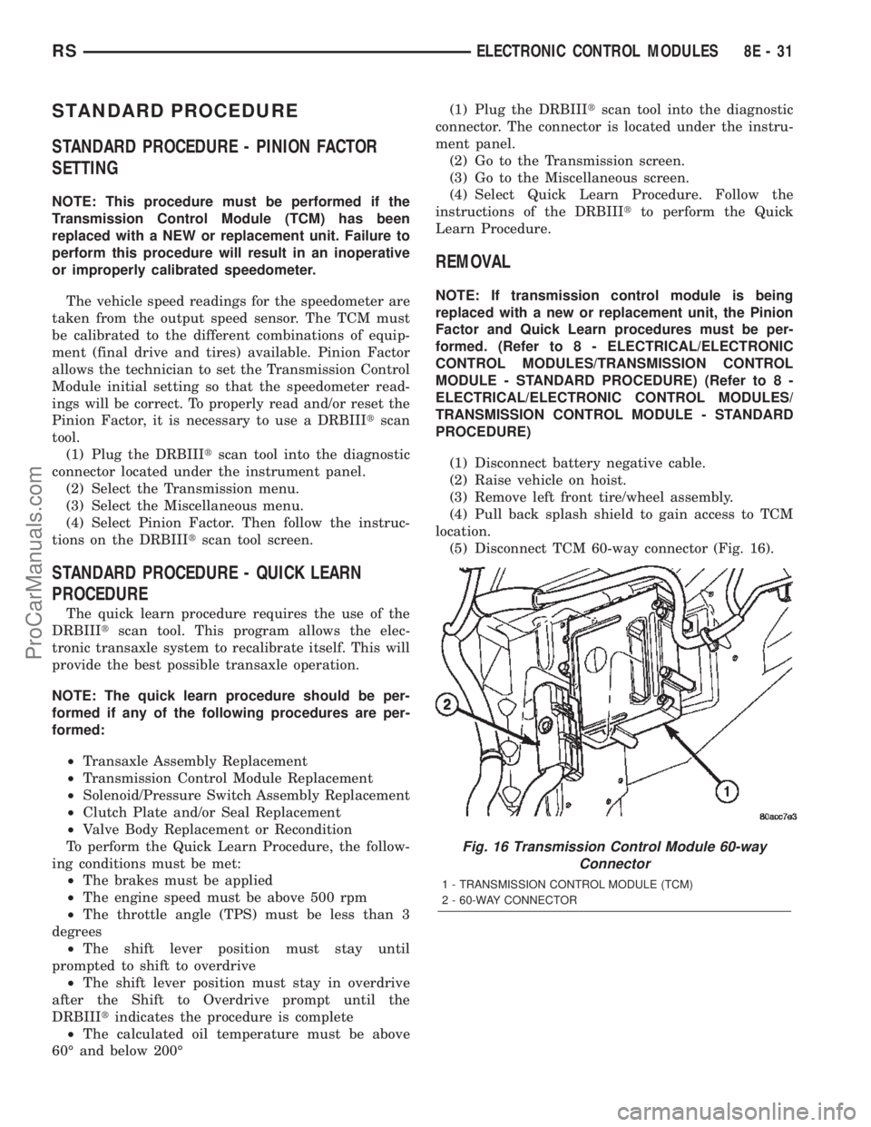
(5) Disconnect TCM 60-way connector (Fig. 16).
Fig. 16 Transmission Control Module 60-way
Connector
1 - TRANSMISSION CONTROL MODULE (TCM)
2 - 60-WAY CONNECTOR
RSELECTRONIC CONTROL MODULES8E-31
ProCarManuals.com
Page 372 of 2399
ELECTRONIC CONTROL MODULES
TABLE OF CONTENTS
page page
ENGINE CONTROL MODULE
DESCRIPTION..........................1
OPERATION............................1
STANDARD PROCEDURE - PCM/ECM/SKIM
PROGRAMMING - DIESEL...............2REMOVAL.............................4
INSTALLATION..........................4
ENGINE CONTROL MODULE
DESCRIPTION
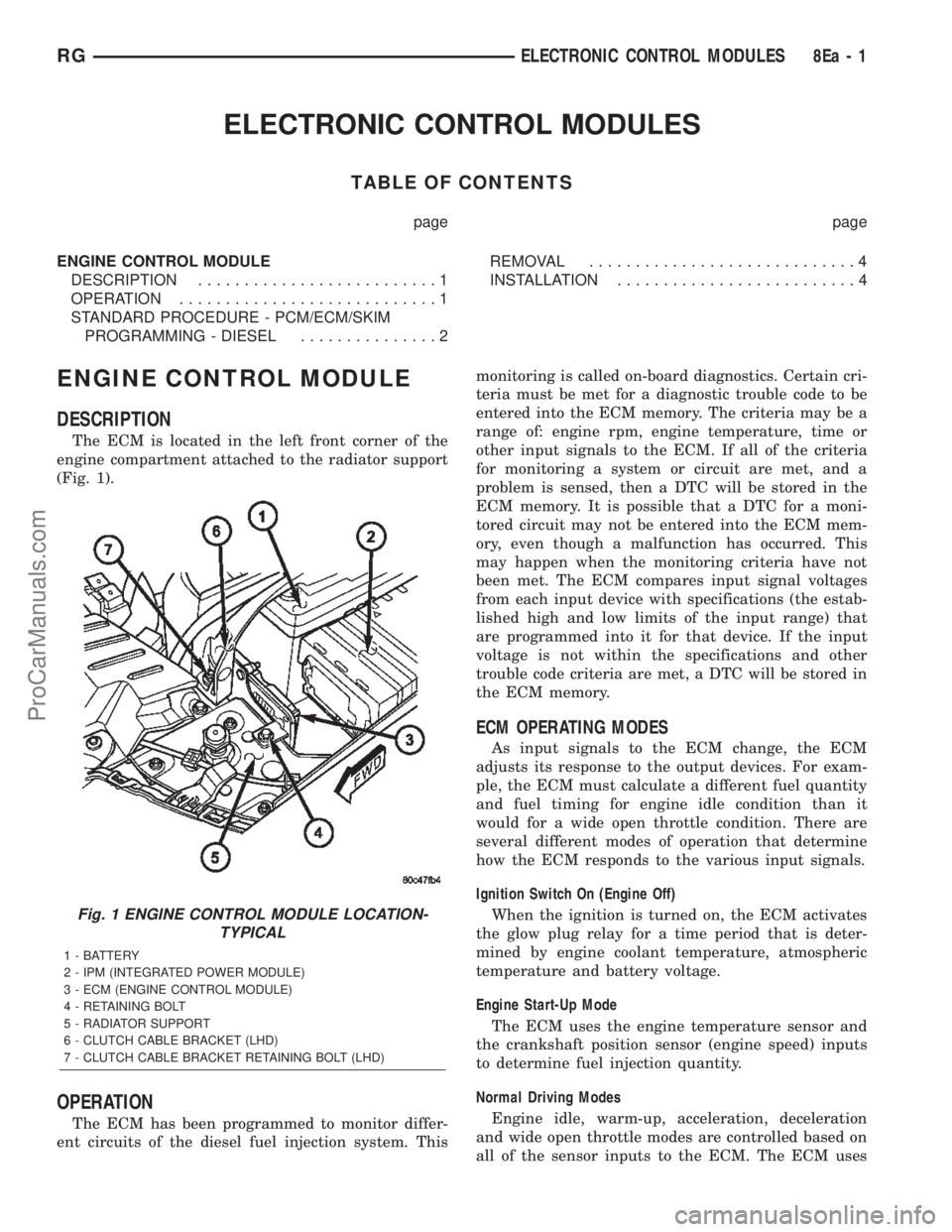
The ECM is located in the left front corner of the
engine compartment attached to the radiator support
(Fig. 1).
OPERATION
The ECM has been programmed to monitor differ-
ent circuits of the diesel fuel injection system. Thismonitoring is called on-board diagnostics. Certain cri-
teria must be met for a diagnostic trouble code to be
entered into the ECM memory. The criteria may be a
range of: engine rpm, engine temperature, time or
other input signals to the ECM. If all of the criteria
for monitoring a system or circuit are met, and a
problem is sensed, then a DTC will be stored in the
ECM memory. It is possible that a DTC for a moni-
tored circuit may not be entered into the ECM mem-
ory, even though a malfunction has occurred. This
may happen when the monitoring criteria have not
been met. The ECM compares input signal voltages
from each input device with specifications (the estab-
lished high and low limits of the input range) that
are programmed into it for that device. If the input
voltage is not within the specifications and other
trouble code criteria are met, a DTC will be stored in
the ECM memory.
ECM OPERATING MODES
As input signals to the ECM change, the ECM
adjusts its response to the output devices. For exam-
ple, the ECM must calculate a different fuel quantity
and fuel timing for engine idle condition than it
would for a wide open throttle condition. There are
several different modes of operation that determine
how the ECM responds to the various input signals.
Ignition Switch On (Engine Off)
When the ignition is turned on, the ECM activates
the glow plug relay for a time period that is deter-
mined by engine coolant temperature, atmospheric
temperature and battery voltage.
Engine Start-Up Mode
The ECM uses the engine temperature sensor and
the crankshaft position sensor (engine speed) inputs
to determine fuel injection quantity.
Normal Driving Modes
Engine idle, warm-up, acceleration, deceleration
and wide open throttle modes are controlled based on
all of the sensor inputs to the ECM. The ECM uses
Fig. 1 ENGINE CONTROL MODULE LOCATION-
TYPICAL
1 - BATTERY
2 - IPM (INTEGRATED POWER MODULE)
3 - ECM (ENGINE CONTROL MODULE)
4 - RETAINING BOLT
5 - RADIATOR SUPPORT
6 - CLUTCH CABLE BRACKET (LHD)
7 - CLUTCH CABLE BRACKET RETAINING BOLT (LHD)
RGELECTRONIC CONTROL MODULES8Ea-1
ProCarManuals.com
Page 373 of 2399
these sensor inputs to adjust fuel quantity and fuel
injector timing.
Limp-In Mode
If there is a fault detected with the accelerator
pedal position sensor, the ECM will set the engine
speed at 1100 RPM.
Overspeed Detection Mode
If the ECM detects engine RPM that exceeds 5200
RPM, the ECM will set a DTC in memory and illu-
minate the MIL until the DTC is cleared.
After-Run Mode
The ECM transfers RAM information to ROM and
performs an Input/Output state check.
MONITORED CIRCUITS
The ECM is able to monitor and identify most
driveability related trouble conditions. Some circuits
are directly monitored through ECM feedback cir-
cuitry. In addition, the ECM monitors the voltage
state of some circuits and compares those states with
expected values. Other systems are monitored indi-
rectly when the ECM conducts a rationality test to
identify problems. Although most subsytems of the
engine control module are either directly or indirectly
monitored, there may be occasions when diagnostic
trouble codes are not immediately identified. For a
trouble code to set, a specific set of conditions must
occur and unless these conditions occur, a DTC will
not set.
DIAGNOSTIC TROUBLE CODES
Each diagnostic trouble code (DTC) is diagnosed by
following a specific procedure. The diagnostic test
procedure contains step-by-step instruction for deter-
mining the cause of the DTC as well as no trouble
code problems. Refer to the appropriate Diesel Pow-
ertrain Diagnostic Manual for more information.
HARD CODE
A DTC that comes back within one cycle of the
ignition key is a hard code. This means that the
problem is current every time the ECM/SKIM checks
that circuit or function. Procedures in this manual
verify if the DTC is a hard code at the beginning of
each test. When the fault is not a hard code, an
intermittent test must be performed. NOTE: If the
DRBIIItdisplays faults for multiple components (i.e.
ECT, VSS, IAT sensors) identify and check the
shared circuits for possible problems before continu-
ing (i.e. sensor grounds or 5-volt supply circuits).
Refer to the appropriate schematic to identify shared
circuits. Refer to the appropriate Diesel Powertrain
Diagnostic Manual for more information.INTERMITTENT CODE
A DTC that is not current every time the ECM/
SKIM checks the circuit or function is an intermit-
tent code. Most intermittent DTCs are caused by
wiring or connector problems. Problems that come
and go like this are the most difficult to diagnose;
they must be looked for under specific conditions that
cause them.NOTE: Electromagnetic (radio)
interference can cause an intermittent system
malfunction.This interference can interrupt com-
munication between the ignition key transponder and
the SKIM. The following checks may assist you in
identifying a possible intermittent problem:
²Visually inspect the related wire harness connec-
tors. Look for broken, bent, pushed out or corroded
terminals.
²Visually inspect the related wire harness. Look
for chafed, pierced or partially broken wire.
²Refer to hotlines or technical service bulletins
that may apply. Refer to the appropriate Diesel Pow-
ertrain Diagnostic Manual for more information.
ECM DIAGNOSTIC TROUBLE CODES
IMPORTANT NOTE: Before replacing the ECM for
a failed driver, control circuit or ground circuit, be
sure to check the related component/circuit integrity
for failures not detected due to a double fault in the
circuit. Most ECM driver/control circuit failures are
caused by internal failures to components (i.e. relays
and solenoids) and shorted circuits (i.e. sensor pull-
ups, drivers and ground circuits). These faults are
difficult to detect when a double fault has occurred
and only one DTC has set. If the DRBIIItdisplays
faults for multiple components (i.e.VSS, ECT, Batt
Temp, etc.) identify and check the shared circuits for
possible problems before continuing (i.e. sensor
grounds or 5-volt supply circuits). Refer to the appro-
priate wiring diagrams to identify shared circuits.
Refer to the appropriate Diesel Powertrain Diagnos-
tic Manual for more information.
STANDARD PROCEDURE - PCM/ECM/SKIM
PROGRAMMING - DIESEL
NOTE: Before replacing the PCM/ECM for a failed
driver, control circuit or ground circuit, be sure to
check the related component/circuit integrity for
failures not detected due to a double fault in the cir-
cuit. Most PCM/ECM driver/control circuit failures
are caused by internal component failures (i.e. relay
and solenoids) and shorted circuits (i.e. pull-ups,
drivers and switched circuits). These failures are
difficult to detect when a double fault has occurred
and only one DTC has set.
8Ea - 2 ELECTRONIC CONTROL MODULESRG
ENGINE CONTROL MODULE (Continued)
ProCarManuals.com
Page 483 of 2399
INSTALLATION - 3.3/3.8L
(1) Install coil over studs on bracket.
(2) Install 2 bolts to ignition coil.
(3) Install 2 nuts to the ignition coil studs. Tighten
nuts and bolts.
(4) Connect the electrical connector to the ignition
coil.
(5) Install the ignition cables to the ignition coil.
(6) Reposition the Power steering reservoir. Slide
bracket over the mounting stud (Fig. 11).
(7) Install 2 bolts to the Power steering reservoir
to intake manifold.
(8) Tighten the lower nut to stud on ignition coil
bracket.
(9) Install the throttle and speed control cables to
clip.
(10) Connect the negative battery cable.
KNOCK SENSOR
DESCRIPTION
The knock sensor threads into the cylinder block.
The knock sensor is designed to detect engine vibra-
tion that is caused by detonation.
OPERATION
When the knock sensor detects a knock in one of
the cylinders, it sends an input signal to the PCM. In
response, the PCM retards ignition timing for all cyl-
inders by a scheduled amount.
Knock sensors contain a piezoelectric material
which constantly vibrates and sends an input voltage
(signal) to the PCM while the engine operates. As the
intensity of the crystal's vibration increases, the
knock sensor output voltage also increases.
The voltage signal produced by the knock sensor
increases with the amplitude of vibration. The PCM
receives as an input the knock sensor voltage signal.
If the signal rises above a predetermined level, the
PCM will store that value in memory and retard
ignition timing to reduce engine knock. If the knock
sensor voltage exceeds a preset value, the PCM
retards ignition timing for all cylinders. It is not a
selective cylinder retard.
The PCM ignores knock sensor input during engine
idle conditions. Once the engine speed exceeds a
specified value, knock retard is allowed.
Knock retard uses its own short term and long
term memory program.
Long term memory stores previous detonation
information in its battery-backed RAM. The maxi-
mum authority that long term memory has over tim-
ing retard can be calibrated.
Short term memory is allowed to retard timing up
to a preset amount under all operating conditions (aslong as rpm is above the minimum rpm) except WOT.
The PCM, using short term memory, can respond
quickly to retard timing when engine knock is
detected. Short term memory is lost any time the
ignition key is turned off.
NOTE: Over or under tightening affects knock sen-
sor performance, possibly causing improper spark
control.
REMOVAL
REMOVAL - 2.4L
The knock sensor threads into the side of the cyl-
inder block in front of the starter (Fig. 12).
(1) Disconnect electrical connector from knock sen-
sor.
(2) Use a crow foot socket to remove the knock
sensors.
REMOVAL - 3.8L
The knock sensor threads into the side of the cyl-
inder block in the rear.
(1) Disconnect the negative battery cable.
(2) Raise vehicle and support.
(3) On All Wheel Drive vehicles remove the PTU
(Power Transfer Unit), refer to the Transmission sec-
tion for more information.
(4) Disconnect electrical connector from knock sen-
sor.
(5) Use a crow foot socket to remove the knock
sensor.
INSTALLATION
INSTALLATION - 2.4L
The knock sensor threads into the side of the cyl-
inder block in front of the starter (Fig. 12).
(1) Install knock sensor. Tighten knock sensor to
10 N´m (7 ft. lbs.) torque.Over or under tighten-
ing effects knock sensor performance, possibly
causing improper spark control.
(2) Attach electrical connector to knock sensor.
INSTALLATION - 3.8L
The knock sensor threads into the side of the cyl-
inder block in the rear.
(1) Install knock sensor. Tighten knock sensor to
10 N´m (7 ft. lbs.) torque.Over or under tighten-
ing effects knock sensor performance, possibly
causing improper spark control.
(2) Attach electrical connector to knock sensor.
8I - 8 IGNITION CONTROLRS
IGNITION COIL (Continued)
ProCarManuals.com
Page 491 of 2399
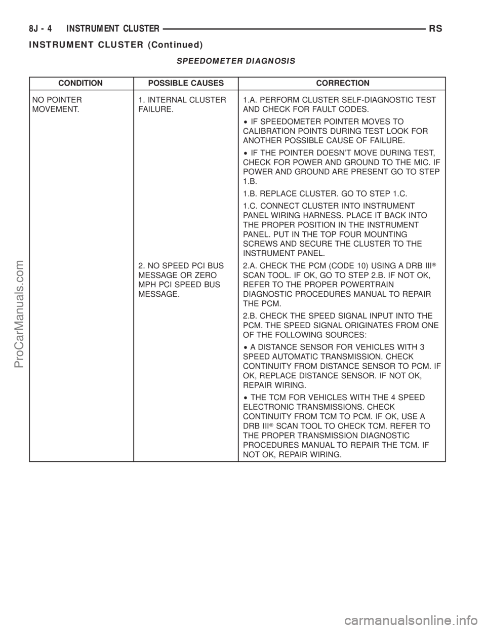
SPEEDOMETER DIAGNOSIS
CONDITION POSSIBLE CAUSES CORRECTION
NO POINTER
MOVEMENT.1. INTERNAL CLUSTER
FAILURE.1.A. PERFORM CLUSTER SELF-DIAGNOSTIC TEST
AND CHECK FOR FAULT CODES.
²IF SPEEDOMETER POINTER MOVES TO
CALIBRATION POINTS DURING TEST LOOK FOR
ANOTHER POSSIBLE CAUSE OF FAILURE.
²IF THE POINTER DOESN'T MOVE DURING TEST,
CHECK FOR POWER AND GROUND TO THE MIC. IF
POWER AND GROUND ARE PRESENT GO TO STEP
1.B.
1.B. REPLACE CLUSTER. GO TO STEP 1.C.
1.C. CONNECT CLUSTER INTO INSTRUMENT
PANEL WIRING HARNESS. PLACE IT BACK INTO
THE PROPER POSITION IN THE INSTRUMENT
PANEL. PUT IN THE TOP FOUR MOUNTING
SCREWS AND SECURE THE CLUSTER TO THE
INSTRUMENT PANEL.
2. NO SPEED PCI BUS
MESSAGE OR ZERO
MPH PCI SPEED BUS
MESSAGE.2.A. CHECK THE PCM (CODE 10) USING A DRB IIIT
SCAN TOOL. IF OK, GO TO STEP 2.B. IF NOT OK,
REFER TO THE PROPER POWERTRAIN
DIAGNOSTIC PROCEDURES MANUAL TO REPAIR
THE PCM.
2.B. CHECK THE SPEED SIGNAL INPUT INTO THE
PCM. THE SPEED SIGNAL ORIGINATES FROM ONE
OF THE FOLLOWING SOURCES:
²A DISTANCE SENSOR FOR VEHICLES WITH 3
SPEED AUTOMATIC TRANSMISSION. CHECK
CONTINUITY FROM DISTANCE SENSOR TO PCM. IF
OK, REPLACE DISTANCE SENSOR. IF NOT OK,
REPAIR WIRING.
²THE TCM FOR VEHICLES WITH THE 4 SPEED
ELECTRONIC TRANSMISSIONS. CHECK
CONTINUITY FROM TCM TO PCM. IF OK, USE A
DRB IIITSCAN TOOL TO CHECK TCM. REFER TO
THE PROPER TRANSMISSION DIAGNOSTIC
PROCEDURES MANUAL TO REPAIR THE TCM. IF
NOT OK, REPAIR WIRING.
8J - 4 INSTRUMENT CLUSTERRS
INSTRUMENT CLUSTER (Continued)
ProCarManuals.com
Page 492 of 2399
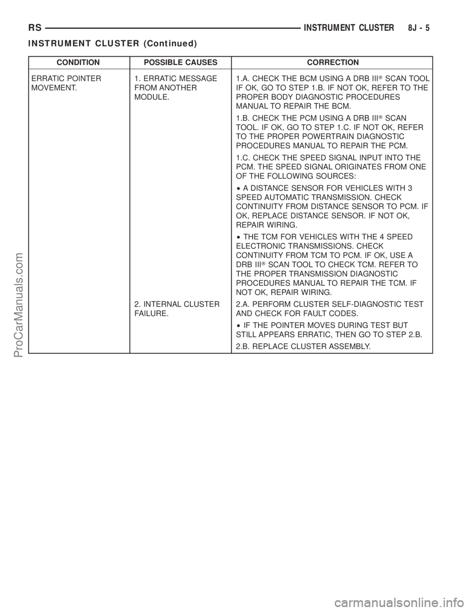
CONDITION POSSIBLE CAUSES CORRECTION
ERRATIC POINTER
MOVEMENT.1. ERRATIC MESSAGE
FROM ANOTHER
MODULE.1.A. CHECK THE BCM USING A DRB IIITSCAN TOOL
IF OK, GO TO STEP 1.B. IF NOT OK, REFER TO THE
PROPER BODY DIAGNOSTIC PROCEDURES
MANUAL TO REPAIR THE BCM.
1.B. CHECK THE PCM USING A DRB IIITSCAN
TOOL. IF OK, GO TO STEP 1.C. IF NOT OK, REFER
TO THE PROPER POWERTRAIN DIAGNOSTIC
PROCEDURES MANUAL TO REPAIR THE PCM.
1.C. CHECK THE SPEED SIGNAL INPUT INTO THE
PCM. THE SPEED SIGNAL ORIGINATES FROM ONE
OF THE FOLLOWING SOURCES:
²A DISTANCE SENSOR FOR VEHICLES WITH 3
SPEED AUTOMATIC TRANSMISSION. CHECK
CONTINUITY FROM DISTANCE SENSOR TO PCM. IF
OK, REPLACE DISTANCE SENSOR. IF NOT OK,
REPAIR WIRING.
²THE TCM FOR VEHICLES WITH THE 4 SPEED
ELECTRONIC TRANSMISSIONS. CHECK
CONTINUITY FROM TCM TO PCM. IF OK, USE A
DRB IIITSCAN TOOL TO CHECK TCM. REFER TO
THE PROPER TRANSMISSION DIAGNOSTIC
PROCEDURES MANUAL TO REPAIR THE TCM. IF
NOT OK, REPAIR WIRING.
2. INTERNAL CLUSTER
FAILURE.2.A. PERFORM CLUSTER SELF-DIAGNOSTIC TEST
AND CHECK FOR FAULT CODES.
²IF THE POINTER MOVES DURING TEST BUT
STILL APPEARS ERRATIC, THEN GO TO STEP 2.B.
2.B. REPLACE CLUSTER ASSEMBLY.
RSINSTRUMENT CLUSTER8J-5
INSTRUMENT CLUSTER (Continued)
ProCarManuals.com
Page 493 of 2399
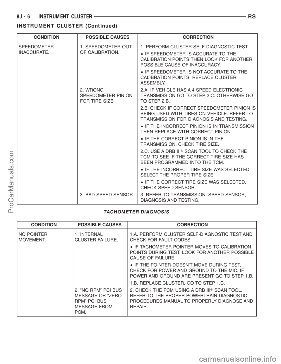
CONDITION POSSIBLE CAUSES CORRECTION
SPEEDOMETER
INACCURATE.1. SPEEDOMETER OUT
OF CALIBRATION.1. PERFORM CLUSTER SELF-DIAGNOSTIC TEST.
²IF SPEEDOMETER IS ACCURATE TO THE
CALIBRATION POINTS THEN LOOK FOR ANOTHER
POSSIBLE CAUSE OF INACCURACY.
²IF SPEEDOMETER IS NOT ACCURATE TO THE
CALIBRATION POINTS, REPLACE CLUSTER
ASSEMBLY.
2. WRONG
SPEEDOMETER PINION
FOR TIRE SIZE.2.A. IF VEHICLE HAS A 4 SPEED ELECTRONIC
TRANSMISSION GO TO STEP 2.C. OTHERWISE GO
TO STEP 2.B.
2.B. CHECK IF CORRECT SPEEDOMETER PINION IS
BEING USED WITH TIRES ON VEHICLE. REFER TO
TRANSMISSION FOR DIAGNOSIS AND TESTING.
²IF THE INCORRECT PINION IS IN TRANSMISSION
THEN REPLACE WITH CORRECT PINION.
²IF THE CORRECT PINION IS IN THE
TRANSMISSION, CHECK TIRE SIZE.
2.C. USE A DRB IIITSCAN TOOL TO CHECK THE
TCM TO SEE IF THE CORRECT TIRE SIZE HAS
BEEN PROGRAMMED INTO THE TCM.
²IF THE INCORRECT TIRE SIZE WAS SELECTED,
SELECT THE PROPER TIRE SIZE.
²IF THE CORRECT TIRE SIZE WAS SELECTED,
CHECK SPEED SENSOR.
3. BAD SPEED SENSOR. 3. REFER TO TRANSMISSION, SPEED SENSOR,
DIAGNOSIS AND TESTING.
TACHOMETER DIAGNOSIS
CONDITION POSSIBLE CAUSES CORRECTION
NO POINTER
MOVEMENT.1. INTERNAL
CLUSTER FAILURE.1.A. PERFORM CLUSTER SELF-DIAGNOSTIC TEST AND
CHECK FOR FAULT CODES.
²IF TACHOMETER POINTER MOVES TO CALIBRATION
POINTS DURING TEST, LOOK FOR ANOTHER POSSIBLE
CAUSE OF FAILURE.
²IF THE POINTER DOESN'T MOVE DURING TEST,
CHECK FOR POWER AND GROUND TO THE MIC. IF
POWER AND GROUND ARE PRESENT GO TO STEP 1.B.
1.B. REPLACE CLUSTER. GO TO STEP 1.C.
2.9NO RPM9PCI BUS
MESSAGE OR9ZERO
RPM9PCI BUS
MESSAGE FROM
PCM.2. CHECK THE PCM USING A DRB IIITSCAN TOOL.
REFER TO THE PROPER POWERTRAIN DIAGNOSTIC
PROCEDURES MANUAL TO PROPERLY DIAGNOSE AND
REPAIR.
8J - 6 INSTRUMENT CLUSTERRS
INSTRUMENT CLUSTER (Continued)
ProCarManuals.com
Page 544 of 2399
The power liftgate control module communicates
on the J1850 Programmable Communication Inter-
face (PCI) Bus Circuit. Therefore, the power liftgate
control module can generate and store its own Diag-
nostic Trouble Codes (DTC). The vehicles Body Con-
trol Module (BCM) receives and supplies messages tothe power liftgate control module via the PCI bus cir-
cuit. A diagnostic scan tool, such as the DRB IIItis
used to read and troubleshoot these Diagnostic Trou-
ble Codes (DTC). Refer to the Body Diagnostic Man-
ual for a complete list of diagnostic routines.
For additional information refer to Power Liftgate
Operation. For a complete system wiring schematic
refer to Wiring Diagrams. For system operation
instructions refer to the vehicles owner manual.
Refer to the Body section of the service manual
for additional information on liftgate components
such as the prop rods, hinges, door alignment and
striker alignment.
WARNING: BE CERTAIN TO READ ALL WARNINGS
AND CAUTIONS (NOTED BELOW) IN POWER LIFT-
GATE SYSTEM OPERATION BEFORE ATTEMPTING
ANY SERVICE OF THE POWER LIFTGATE SYSTEM
OR COMPONENTS.
OPERATION
With the push of a power liftgate open/close com-
mand switch (key fob or overhead console mounted) a
signal is sent out on the J1850 PCI Data Bus circuit.
This signal is detected at the body control module
(BCM). The BCM then sends a signal out on the
J1850 PCI Data Bus circuit to the power liftgate
module. The power liftgate module then signals the
power liftgate motor to start an open or close cycle,
depending on what position the liftgate is in open or
closed.
During a liftgate open or close cycle, if the power
liftgate module detects sufficient resistance to liftgate
travel, such as an obstruction in the liftgates path,
the power liftgate control module will immediately
stop the liftgate movement and reverse travel to the
full open or closed position. The ability for the power
liftgate module to detect resistance to liftgate travel
is accomplished by hall effect sensors, drive motor
speed and pinch sensors (tape switches).
The power liftgate control module has the ability to
learn. Anytime the liftgate is opened or closed using
the power liftgate system the module learns from its
cycle. If a replacement power liftgate component is
installed or a liftgate adjustment is made, the mod-
ule will relearn the effort and/or time required to
open or close the door. This learn cycle can be per-
formed with a Diagnostic Scan Tool, such as the DRB
IIItor with a complete cycle of the liftgate, using
any one of the command switches. Refer to Standard
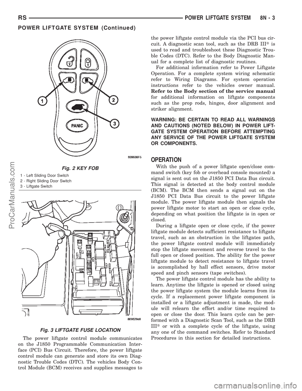
Procedures in this section for detailed instructions.Fig. 2 KEY FOB
1 - Left Sliding Door Switch
2 - Right Sliding Door Switch
3 - Liftgate Switch
Fig. 3 LIFTGATE FUSE LOCATION
RSPOWER LIFTGATE SYSTEM8N-3
POWER LIFTGATE SYSTEM (Continued)
ProCarManuals.com
Page 551 of 2399
WARNING: USE EXTREME CAUTION WHEN TEST-
ING PINCH SENSOR OPERATION.
FULL OPEN SWITCH
DESCRIPTION
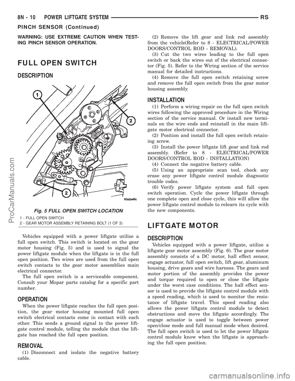
Vehicles equipped with a power liftgate utilize a
full open switch. This switch is located on the gear
motor housing (Fig. 5) and is used to signal the
power liftgate module when the liftgate is in the full
open position. Two wires are used from the full open
switch contacts to the gear motor assemblies main
electrical connector.
The full open switch is a serviceable component.
Consult your Mopar parts catalog for a specific part
number.
OPERATION
When the power liftgate reaches the full open posi-
tion, the gear motor housing mounted full open
switch electrical contacts come in contact with each
other. This sends a ground signal to the power lift-
gate control module, telling the module that the lift-
gate has reached the full open position.
REMOVAL
(1) Disconnect and isolate the negative battery
cable.(2) Remove the lift gear and link rod assembly
from the vehicle(Refer to 8 - ELECTRICAL/POWER
DOORS/CONTROL ROD - REMOVAL).
(3) Cut the two wires leading to the full open
switch or back the wires out of the electrical connec-
tor (Fig. 5). Refer to the Wiring section of the service
manual for detailed instructions.
(4) Remove the full open switch retaining screw
and remove the full open switch from the gear motor
housing assembly.
INSTALLATION
(1) Perform a wiring repair on the full open switch
wires following the approved procedure in the Wiring
section of the service manual. Or install new termi-
nals on the wire ends and reinstall in the main lift-
gate motor electrical connector.
(2) Position and install the full open switch retain-
ing screw.
(3) Install the power liftgate lift gear and link rod
assembly. (Refer to 8 - ELECTRICAL/POWER
DOORS/CONTROL ROD - INSTALLATION)
(4) Connect the negative battery cable.
(5) Using an appropriate scan tool, check any
erase any power liftgate control module diagnostic
trouble codes.
(6) Verify power liftgate system and full open
switch operation. Cycle the power liftgate through
one complete open and close cycle, this will allow the
power liftgate control module to relearn its cycle with
the new components.
LIFTGATE MOTOR
DESCRIPTION
Vehicles equipped with a power liftgate, utilize a
liftgate gear motor assembly (Fig. 6). The gear motor
assembly consists of a DC motor, hall effect sensor,
engage actuator, full open switch, lift gear, aluminum
housing, drive gears and wire harness. The gears and
motor portion of the assembly provides the power
and torque required to open or close the liftgate
under the worst case conditions. The hall effect sen-
sor is used to provide the liftgate control module with
a speed reading, which is used to monitor the resis-
tance of liftgate travel. This speed reading also
allows the power liftgate control module to detect
obstructions and move the liftgate accordingly. The
engage actuator is used to toggle between power
open/close mode and full manual mode when desired.
The full open switch is used to let the power liftgate
control module know when the liftgate is approach-
ing the full open position.
Fig. 5 FULL OPEN SWITCH LOCATION
1 - FULL OPEN SWITCH
2 - GEAR MOTOR ASSEMBLY RETAINING BOLT (1 OF 3)
8N - 10 POWER LIFTGATE SYSTEMRS
PINCH SENSOR (Continued)
ProCarManuals.com
Page 561 of 2399
read and diagnose these trouble codes. Refer to the
Body Diagnostic Manual for a complete list of diag-
nostic routines.
NOTE: It may be possible to generate Sliding Door
Diagnostic Trouble Codes during normal power
sliding door operation. Refer to the Body Diagnos-
tic Manual for a complete list of diagnostic routines.
For additional information, (Refer to 8 - ELECTRI-
CAL/POWER DOORS - OPERATION). For a com-
plete power sliding door system wiring schematic,
refer to Wiring Diagrams. For power sliding door sys-
tem operation instructions, refer to the vehicle owner
manual.
WARNING: BE CERTAIN TO READ ALL WARNINGS
AND CAUTIONS IN POWER SLIDING DOOR OPER-
ATION BEFORE ATTEMPTING ANY SERVICE OF
POWER SLIDING DOOR SYSTEM OR COMPO-
NENTS.
OPERATION
With the push of a power sliding door open/close
command switch (key fob, overhead console or B-pil-
lar mounted) a signal is sent out to the Body Control
Module (BCM). The BCM then sends a signal out on
the PCI Data Bus circuit (J1850) to the power sliding
door module. The power sliding door module then
signals the power sliding door latch to release the
door to the unlatched and movable position. The
motor then starts an open cycle.During the door open cycle, if the power sliding
door module detects sufficient resistance to door
travel, such as an obstruction in the door's path, the
power sliding door module will immediately stop door
movement and reverse door travel to the full open or
closed position. The ability for the power sliding door
module to detect resistance to door travel is accom-
plished by hall effect sensors and the door motor
speed.
The power sliding door control module has the abil-
ity to learn. Anytime a door is opened or closed using
the power sliding door system the module learns
from its cycle. If a replacement power sliding door
component is installed or a door adjustment is made,
the module must re-learn the effort required to open
or close the door. A learn cycle can be performed with
a Diagnostic Scan Tool, such as the DRB IIIt, or with
a complete cycle of the door, using any one of the
command switches. Refer to Standard Procedures in
this section for detailed instructions.
The power sliding door system is designed with a
number of system inhibitors. These inhibitors are
necessary for safety and/or feasibility of the power
sliding door system. See the power sliding door sys-
tem inhibitors noted below:
POWER SLIDING DOOR SYSTEM INHIBITORS
²The power sliding door must be in thefullopen
or closed position in order for the power sliding door
system to start a cycle. If the door is not in this posi-
tion (based on the input from the full open, pawl or
ratchet switches) the door control module will not
respond to command switch inputs.
²The vehicles transmission must be inpark or
neutralin order for the power sliding door system to
start a cycle.
²The vehicles child lockout switch must be in the
ªUNLOCKEDº position in order for the power sliding
door systems B-pillar switches to function.
²If multiple obstacles are detected during the
same power open or close cycle the power sliding
door may go into full manual mode.
²If severe Diagnostic Trouble Codes (DTC) are
stored in the power sliding door control module the
power sliding door may go into full manual mode.
²Due to the high pressure created in the passen-
ger compartment with the blower motor on high, the
power sliding door may not complete a power close
cycle unless a window is cracked, allowing the pres-
sure to escape. This situation will only be experi-
enced on some vehicles, or vehicles with brand new
side door weather seals installed. Refer to the Side
Door Adjustment procedure in the Standard Proce-
dures section of this group.
²The vehicles fuel tank filler door must be in the
closed position. Due to the sliding door interference
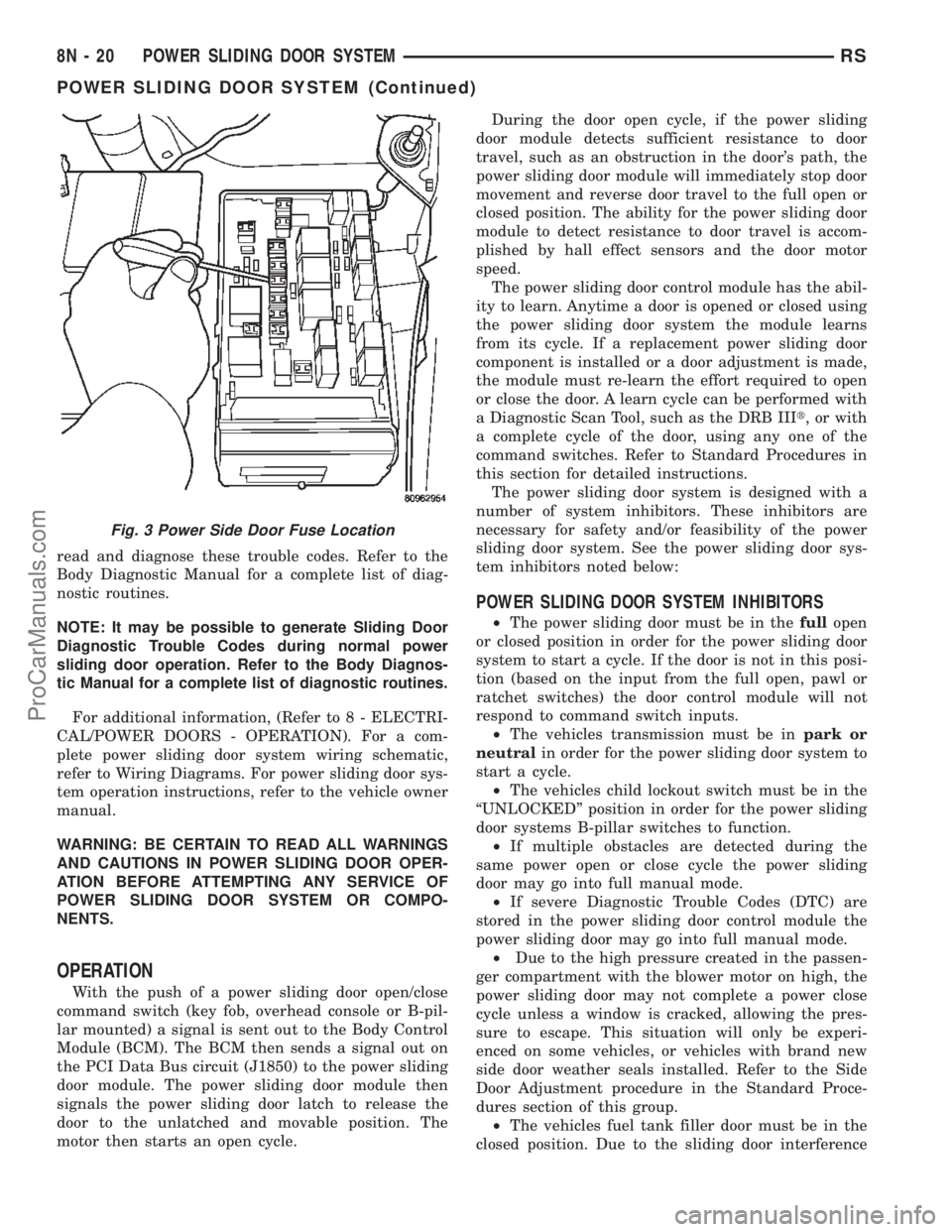
Fig. 3 Power Side Door Fuse Location
8N - 20 POWER SLIDING DOOR SYSTEMRS
POWER SLIDING DOOR SYSTEM (Continued)
ProCarManuals.com