Brake line CHRYSLER VOYAGER 2002 Workshop Manual
[x] Cancel search | Manufacturer: CHRYSLER, Model Year: 2002, Model line: VOYAGER, Model: CHRYSLER VOYAGER 2002Pages: 2399, PDF Size: 57.96 MB
Page 1138 of 2399
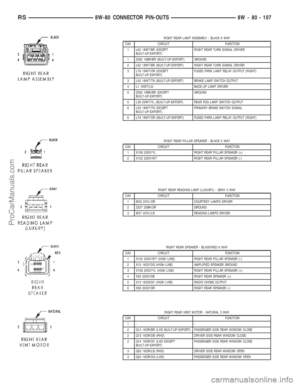
RIGHT REAR LAMP ASSEMBLY - BLACK 6 WAY
CAV CIRCUIT FUNCTION
1 L62 18WT/BR (EXCEPT
BUILT-UP-EXPORT)RIGHT REAR TURN SIGNAL DRIVER
1 Z362 18BK/BR (BUILT-UP-EXPORT) GROUND
2 L62 18WT/BR (BUILT-UP-EXPORT) RIGHT REAR TURN SIGNAL DRIVER
3 L78 18WT/OR (EXCEPT
BUILT-UP-EXPORT)FUSED PARK LAMP RELAY OUTPUT (RIGHT)
3 L50 18WT/TN (BUILT-UP-EXPORT) BRAKE LAMP SWITCH OUTPUT
4 L1 18WT/LG BACK-UP LAMP DRIVER
5 Z362 18BK/BR (EXCEPT
BUILT-UP-EXPORT)GROUND
5 L38 20WT/YL (BUILT-UP-EXPORT) REAR FOG LAMP SWITCH OUTPUT
6 L50 18WT/TN (EXCEPT
BUILT-UP-EXPORT)PRIMARY BRAKE SWITCH SIGNAL
6 L78 18WT/OR (BUILT-UP-EXPORT) FUSED PARK LAMP RELAY OUTPUT (RIGHT)
RIGHT REAR PILLAR SPEAKER - BLACK 2 WAY
CAV CIRCUIT FUNCTION
1 X158 20GY/YL RIGHT REAR PILLAR SPEAKER (+)
2 X152 20GY/WT RIGHT REAR PILLAR SPEAKER (-)
RIGHT REAR READING LAMP (LUXURY) - GRAY 3 WAY
CAV CIRCUIT FUNCTION
1 M22 20YL/OR COURTESY LAMPS DRIVER
2 Z327 20BK/OR GROUND
3 M27 20YL/LB READING LAMPS DRIVER
RIGHT REAR SPEAKER - BLACK/RED 6 WAY
CAV CIRCUIT FUNCTION
1 X152 20GY/WT (HIGH LINE) RIGHT REAR PILLAR SPEAKER (-)
2 X15 16GY/DG (HIGH LINE) AMPLIFIED SPEAKER GROUND
3 X158 20GY/YL (HIGH LINE) RIGHT REAR PILLAR SPEAKER (+)
4 X52 20GY/DB RIGHT REAR SPEAKER (+)
5 X13 16DG/GY (HIGH LINE) RADIO CHOKE OUTPUT
6 X58 20GY/OR RIGHT REAR SPEAKER (-)
RIGHT REAR VENT MOTOR - NATURAL 3 WAY
CAV CIRCUIT FUNCTION
1- -
2 Q14 16OR/BR (LHD BUILT-UP-EXPORT) PASSENGER SIDE REAR WINDOW CLOSE
2 Q13 16OR/DB (RHD) DRIVER SIDE REAR WINDOW CLOSE
2 Q14 16OR/GY (LHD EXCEPT
BUILT-UP-EXPORT)PASSENGER SIDE REAR WINDOW CLOSE
3 Q23 16OR/LB (RHD) DRIVER SIDE REAR WINDOW OPEN
3 Q24 16OR/DG (LHD) PASSENGER SIDE REAR WINDOW OPEN
RS8W-80 CONNECTOR PIN-OUTS8W - 80 - 107
ProCarManuals.com
Page 1261 of 2399
INTAKE MANIFOLD - UPPER
REMOVAL
(1) Disconnect negative cable from battery.
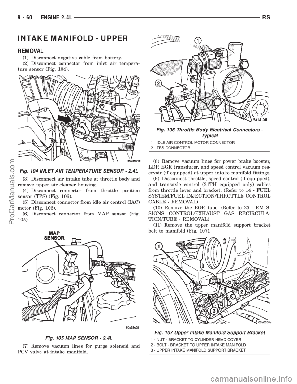
(2) Disconnect connector from inlet air tempera-
ture sensor (Fig. 104).
(3) Disconnect air intake tube at throttle body and
remove upper air cleaner housing.
(4) Disconnect connector from throttle position
sensor (TPS) (Fig. 106).
(5) Disconnect connector from idle air control (IAC)
motor (Fig. 106).
(6) Disconnect connector from MAP sensor (Fig.
105).
(7) Remove vacuum lines for purge solenoid and
PCV valve at intake manifold.(8) Remove vacuum lines for power brake booster,
LDP, EGR transducer, and speed control vacuum res-
ervoir (if equipped) at upper intake manifold fittings.
(9) Disconnect throttle, speed control (if equipped),
and transaxle control (31TH equipped only) cables
from throttle lever and bracket. (Refer to 14 - FUEL
SYSTEM/FUEL INJECTION/THROTTLE CONTROL
CABLE - REMOVAL)
(10) Remove the EGR tube. (Refer to 25 - EMIS-
SIONS CONTROL/EXHAUST GAS RECIRCULA-
TION/TUBE - REMOVAL)
(11) Remove the upper manifold support bracket
bolt to manifold (Fig. 107).
Fig. 104 INLET AIR TEMPERATURE SENSOR - 2.4L
Fig. 105 MAP SENSOR - 2.4L
Fig. 106 Throttle Body Electrical Connectors -
Typical
1 - IDLE AIR CONTROL MOTOR CONNECTOR
2 - TPS CONNECTOR
Fig. 107 Upper Intake Manifold Support Bracket
1 - NUT - BRACKET TO CYLINDER HEAD COVER
2 - BOLT - BRACKET TO UPPER INTAKE MANIFOLD
3 - UPPER INTAKE MANIFOLD SUPPORT BRACKET
9 - 60 ENGINE 2.4LRS
ProCarManuals.com
Page 1262 of 2399
(12) Remove engine oil dipstick from tube.
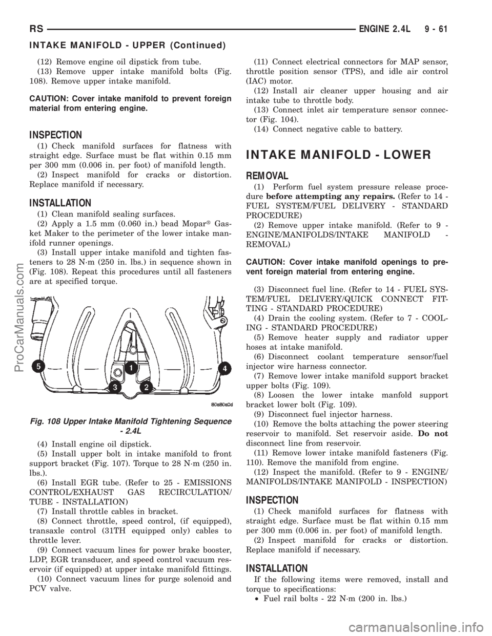
(13) Remove upper intake manifold bolts (Fig.
108). Remove upper intake manifold.
CAUTION: Cover intake manifold to prevent foreign
material from entering engine.
INSPECTION
(1) Check manifold surfaces for flatness with
straight edge. Surface must be flat within 0.15 mm
per 300 mm (0.006 in. per foot) of manifold length.
(2) Inspect manifold for cracks or distortion.
Replace manifold if necessary.
INSTALLATION
(1) Clean manifold sealing surfaces.
(2) Apply a 1.5 mm (0.060 in.) bead MopartGas-
ket Maker to the perimeter of the lower intake man-
ifold runner openings.
(3) Install upper intake manifold and tighten fas-
teners to 28 N´m (250 in. lbs.) in sequence shown in
(Fig. 108). Repeat this procedures until all fasteners
are at specified torque.
(4) Install engine oil dipstick.
(5) Install upper bolt in intake manifold to front
support bracket (Fig. 107). Torque to 28 N´m (250 in.
lbs.).
(6) Install EGR tube. (Refer to 25 - EMISSIONS
CONTROL/EXHAUST GAS RECIRCULATION/
TUBE - INSTALLATION)
(7) Install throttle cables in bracket.
(8) Connect throttle, speed control, (if equipped),
transaxle control (31TH equipped only) cables to
throttle lever.
(9) Connect vacuum lines for power brake booster,
LDP, EGR transducer, and speed control vacuum res-
ervoir (if equipped) at upper intake manifold fittings.
(10) Connect vacuum lines for purge solenoid and
PCV valve.(11) Connect electrical connectors for MAP sensor,
throttle position sensor (TPS), and idle air control
(IAC) motor.
(12) Install air cleaner upper housing and air
intake tube to throttle body.
(13) Connect inlet air temperature sensor connec-
tor (Fig. 104).
(14) Connect negative cable to battery.
INTAKE MANIFOLD - LOWER
REMOVAL
(1) Perform fuel system pressure release proce-
durebefore attempting any repairs.(Refer to 14 -
FUEL SYSTEM/FUEL DELIVERY - STANDARD
PROCEDURE)
(2) Remove upper intake manifold. (Refer to 9 -
ENGINE/MANIFOLDS/INTAKE MANIFOLD -
REMOVAL)
CAUTION: Cover intake manifold openings to pre-
vent foreign material from entering engine.
(3) Disconnect fuel line. (Refer to 14 - FUEL SYS-
TEM/FUEL DELIVERY/QUICK CONNECT FIT-
TING - STANDARD PROCEDURE)
(4) Drain the cooling system. (Refer to 7 - COOL-
ING - STANDARD PROCEDURE)
(5) Remove heater supply and radiator upper
hoses at intake manifold.
(6) Disconnect coolant temperature sensor/fuel
injector wire harness connector.
(7) Remove lower intake manifold support bracket
upper bolts (Fig. 109).
(8) Loosen the lower intake manfold support
bracket lower bolt (Fig. 109).
(9) Disconnect fuel injector harness.
(10) Remove the bolts attaching the power steering
reservoir to manifold. Set reservoir aside.Do not
disconnect line from reservoir.
(11) Remove lower intake manifold fasteners (Fig.
110). Remove the manifold from engine.
(12) Inspect the manifold. (Refer to 9 - ENGINE/
MANIFOLDS/INTAKE MANIFOLD - INSPECTION)
INSPECTION
(1) Check manifold surfaces for flatness with
straight edge. Surface must be flat within 0.15 mm
per 300 mm (0.006 in. per foot) of manifold length.
(2) Inspect manifold for cracks or distortion.
Replace manifold if necessary.
INSTALLATION
If the following items were removed, install and
torque to specifications:
²Fuel rail bolts - 22 N´m (200 in. lbs.)
Fig. 108 Upper Intake Manifold Tightening Sequence
- 2.4L
RSENGINE 2.4L9-61
INTAKE MANIFOLD - UPPER (Continued)
ProCarManuals.com
Page 1288 of 2399
REMOVAL - ENGINE ASSEMBLY
(1) Perform fuel pressure release procedure (Refer
to 14 - FUEL SYSTEM/FUEL DELIVERY - STAN-
DARD PROCEDURE).
(2) Disconnect negative battery cable.
(3) Remove air cleaner and hoses.
(4) Disconnect the fuel line from fuel rail (Refer to
14 - FUEL SYSTEM/FUEL DELIVERY/QUICK
CONNECT FITTING - STANDARD PROCEDURE).
(5) Remove the wiper module (Refer to 8 - ELEC-
TRICAL/WIPERS/WASHERS/WIPER MODULE -
REMOVAL).
(6) Block off heater hoses to the rear heater sys-
tem using pinch-off pliers (if equipped).
(7) Drain the cooling system (Refer to 7 - COOL-
ING - STANDARD PROCEDURE).
(8) Disconnect the heater hoses.
(9) Remove the radiator upper support crossmem-
ber (Refer to 23 - BODY/EXTERIOR/GRILLE OPEN-
ING REINFORCEMENT - REMOVAL).
(10) Remove the radiator fans (Refer to 7 - COOL-
ING/ENGINE/RADIATOR FAN - REMOVAL).
(11) Disconnect the throttle cables from the throt-
tle body.
(12) Disconnect the MAP, IAC, and TPS electrical
connectors.
(13) Disconnect the EGR transducer electrical con-
nector (if equipped).
(14) Disconnect the vacuum hoses from throttle
body.
(15) Disconnect the brake booster and speed con-
trol vacuum hoses.
(16) Disengage wire harness clip from the right
side engine mount.
(17) Remove the power steering reservoir from
mounting position and set aside.Do notdisconnect
hose.
(18) Disconnect ground strap from rear of cylinder
head.
(19) Disconnect engine coolant temperature (ECT)
sensor and ignition coil electrical connectors.
(20) Disconnect the fuel injector electrical harness
connector and disengage clip from support bracket.
(21) Disconnect camshaft and crankshaft position
sensor electrical connectors.
(22) Evacuate air conditioning system. Refer to 24
- HEATING & AIR CONDITIONING.
(23) Disconnect A/C compressor electrical connec-
tor.(24) Disconnect the A/C lines from compressor.
Cover and seal all openings of hoses and compressor.
(25) Remove the radiator upper hose.
(26) Disengage electrical harness clip at transaxle
dipstick tube.
(27) Remove transaxle dipstick tube. Seal opening
using a suitable plug.
NOTE: When the transaxle cooler lines are removed
from the rolled-groove type fittings at the transaxle,
damage to the inner wall of the hose will occur. To
prevent prevent potential leakage, the cooler hoses
must be cut off flush at the transaxle fitting, and a
service cooler hose splice kit must be installed
upon reassembly.
(28) Using a blade or suitable hose cutter, cut
transaxle oil cooler lines off flush with fittings. Plug
cooler lines and fittings to prevent debris from enter-
ing transaxle or cooler circuit. A service splice kit will
be installed upon reassembly.
(29) Disconnect transaxle shift linkage and electri-
cal connectors.
(30) Raise vehicle on hoist and drain the engine
oil.
(31) Remove the axle shafts. (Refer to 3 - DIFFER-
ENTIAL & DRIVELINE/HALF SHAFT - REMOVAL)
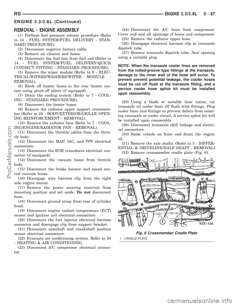
(32) Remove crossmember cradle plate (Fig. 6).
Fig. 6 Crossmember Cradle Plate
1 - CRADLE PLATE
RSENGINE 3.3/3.8L9-87
ENGINE 3.3/3.8L (Continued)
ProCarManuals.com
Page 1292 of 2399
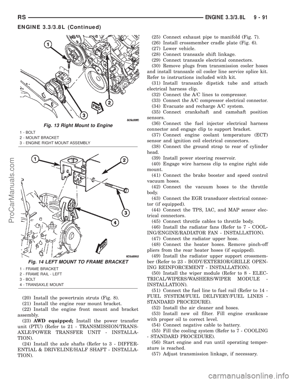
(20) Install the powertrain struts (Fig. 8).
(21) Install the engine rear mount bracket.
(22) Install the engine front mount and bracket
assembly.
(23)AWD equipped;Install the power transfer
unit (PTU) (Refer to 21 - TRANSMISSION/TRANS-
AXLE/POWER TRANSFER UNIT - INSTALLA-
TION).
(24) Install the axle shafts (Refer to 3 - DIFFER-
ENTIAL & DRIVELINE/HALF SHAFT - INSTALLA-
TION).(25) Connect exhaust pipe to manifold (Fig. 7).
(26) Install crossmember cradle plate (Fig. 6).
(27) Lower vehicle.
(28) Connect transaxle shift linkage.
(29) Connect transaxle electrical connectors.
(30) Remove plugs from transmission cooler hoses
and install transaxle oil cooler line service splice kit.
Refer to instructions included with kit.
(31) Install transaxle dipstick tube and attach
electrical harness clip.
(32) Connect the A/C lines to compressor.
(33)
Connect the A/C compressor electrical connector.
(34) Evacuate and recharge A/C system.
(35) Connect crankshaft and camshaft position
sensors.
(36) Connect the fuel injector electrical harness
connector and engage clip to support bracket.
(37) Connect engine coolant temperature (ECT)
sensor and ignition coil electrical connectors.
(38) Connect the ground strap to rear of cylinder
head.
(39) Install power steering reservoir.
(40) Engage wire harness clip to engine right side
mount.
(41) Connect the brake booster and speed control
vacuum hoses.
(42) Connect the vacuum hoses to the throttle
body.
(43) Connect the EGR transducer electrical connec-
tor (if equipped).
(44) Connect the TPS, IAC, and MAP sensor elec-
trical connectors.
(45) Connect throttle cables to throttle body.
(46) Install the radiator fans (Refer to 7 - COOL-
ING/ENGINE/RADIATOR FAN - INSTALLATION).
(47) Connect the radiator upper hose.
(48) Connect the heater hoses. Remove pinch-off
pliers from the rear heater hoses (if equipped).
(49) Install the radiator upper support crossmem-
ber (Refer to 23 - BODY/EXTERIOR/GRILLE OPEN-
ING REINFORCEMENT - INSTALLATION).
(50) Install the wiper module (Refer to 8 - ELEC-
TRICAL/WIPERS/WASHERS/WIPER MODULE -
INSTALLATION).
(51) Connect the fuel line to fuel rail (Refer to 14 -
FUEL SYSTEM/FUEL DELIVERY/FUEL LINES -
STANDARD PROCEDURE).
(52) Install the air cleaner and hoses.
(53) Install new oil filter. Fill engine crankcase
with proper oil to correct level.
(54) Connect negative cable to battery.
(55) Fill the cooling system (Refer to 7 - COOLING
- STANDARD PROCEDURE).
(56) Start engine and run until operating temper-
ature is reached.
(57) Adjust transmission linkage, if necessary.
Fig. 13 Right Mount to Engine
1 - BOLT
2 - MOUNT BRACKET
3 - ENGINE RIGHT MOUNT ASSEMBLY
Fig. 14 LEFT MOUNT TO FRAME BRACKET
1 - FRAME BRACKET
2 - FRAME RAIL - LEFT
3 - BOLT
4 - TRANSAXLE MOUNT
RSENGINE 3.3/3.8L9-91
ENGINE 3.3/3.8L (Continued)
ProCarManuals.com
Page 1365 of 2399
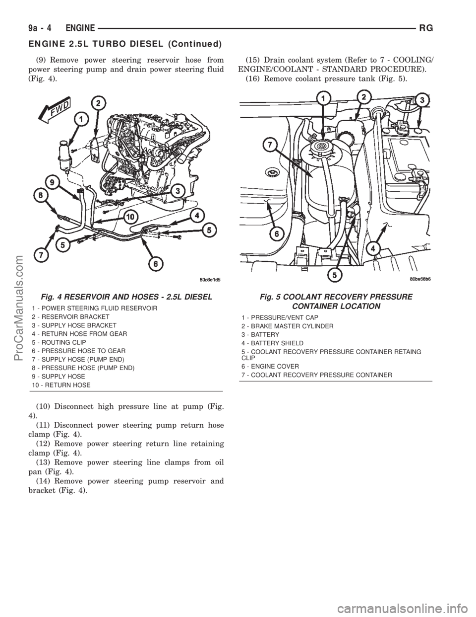
(9) Remove power steering reservoir hose from
power steering pump and drain power steering fluid
(Fig. 4).
(10) Disconnect high pressure line at pump (Fig.
4).
(11) Disconnect power steering pump return hose
clamp (Fig. 4).
(12) Remove power steering return line retaining
clamp (Fig. 4).
(13) Remove power steering line clamps from oil
pan (Fig. 4).
(14) Remove power steering pump reservoir and
bracket (Fig. 4).(15) Drain coolant system (Refer to 7 - COOLING/
ENGINE/COOLANT - STANDARD PROCEDURE).
(16) Remove coolant pressure tank (Fig. 5).
Fig. 4 RESERVOIR AND HOSES - 2.5L DIESEL
1 - POWER STEERING FLUID RESERVOIR
2 - RESERVOIR BRACKET
3 - SUPPLY HOSE BRACKET
4 - RETURN HOSE FROM GEAR
5 - ROUTING CLIP
6 - PRESSURE HOSE TO GEAR
7 - SUPPLY HOSE (PUMP END)
8 - PRESSURE HOSE (PUMP END)
9 - SUPPLY HOSE
10 - RETURN HOSE
Fig. 5 COOLANT RECOVERY PRESSURE
CONTAINER LOCATION
1 - PRESSURE/VENT CAP
2 - BRAKE MASTER CYLINDER
3 - BATTERY
4 - BATTERY SHIELD
5 - COOLANT RECOVERY PRESSURE CONTAINER RETAING
CLIP
6 - ENGINE COVER
7 - COOLANT RECOVERY PRESSURE CONTAINER
9a - 4 ENGINERG
ENGINE 2.5L TURBO DIESEL (Continued)
ProCarManuals.com
Page 1366 of 2399
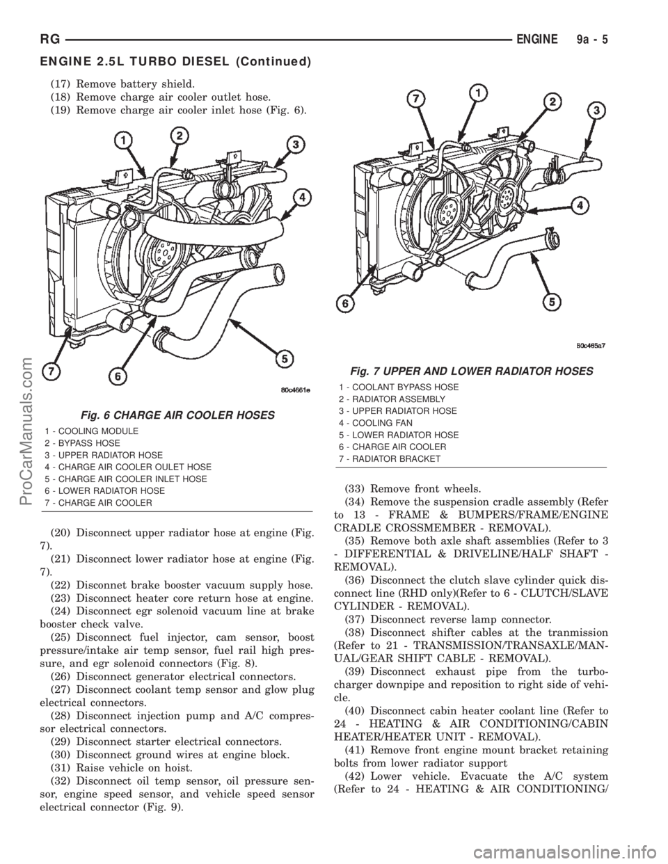
(17) Remove battery shield.
(18) Remove charge air cooler outlet hose.
(19) Remove charge air cooler inlet hose (Fig. 6).
(20) Disconnect upper radiator hose at engine (Fig.
7).
(21) Disconnect lower radiator hose at engine (Fig.
7).
(22) Disconnet brake booster vacuum supply hose.
(23) Disconnect heater core return hose at engine.
(24) Disconnect egr solenoid vacuum line at brake
booster check valve.
(25) Disconnect fuel injector, cam sensor, boost
pressure/intake air temp sensor, fuel rail high pres-
sure, and egr solenoid connectors (Fig. 8).
(26) Disconnect generator electrical connectors.
(27) Disconnect coolant temp sensor and glow plug
electrical connectors.
(28) Disconnect injection pump and A/C compres-
sor electrical connectors.
(29) Disconnect starter electrical connectors.
(30) Disconnect ground wires at engine block.
(31) Raise vehicle on hoist.
(32) Disconnect oil temp sensor, oil pressure sen-
sor, engine speed sensor, and vehicle speed sensor
electrical connector (Fig. 9).(33) Remove front wheels.
(34) Remove the suspension cradle assembly (Refer
to 13 - FRAME & BUMPERS/FRAME/ENGINE
CRADLE CROSSMEMBER - REMOVAL).
(35) Remove both axle shaft assemblies (Refer to 3
- DIFFERENTIAL & DRIVELINE/HALF SHAFT -
REMOVAL).
(36) Disconnect the clutch slave cylinder quick dis-
connect line (RHD only)(Refer to 6 - CLUTCH/SLAVE
CYLINDER - REMOVAL).
(37) Disconnect reverse lamp connector.
(38) Disconnect shifter cables at the tranmission
(Refer to 21 - TRANSMISSION/TRANSAXLE/MAN-
UAL/GEAR SHIFT CABLE - REMOVAL).
(39) Disconnect exhaust pipe from the turbo-
charger downpipe and reposition to right side of vehi-
cle.
(40) Disconnect cabin heater coolant line (Refer to
24 - HEATING & AIR CONDITIONING/CABIN
HEATER/HEATER UNIT - REMOVAL).
(41) Remove front engine mount bracket retaining
bolts from lower radiator support
(42) Lower vehicle. Evacuate the A/C system
(Refer to 24 - HEATING & AIR CONDITIONING/
Fig. 6 CHARGE AIR COOLER HOSES
1 - COOLING MODULE
2 - BYPASS HOSE
3 - UPPER RADIATOR HOSE
4 - CHARGE AIR COOLER OULET HOSE
5 - CHARGE AIR COOLER INLET HOSE
6 - LOWER RADIATOR HOSE
7 - CHARGE AIR COOLER
Fig. 7 UPPER AND LOWER RADIATOR HOSES
1 - COOLANT BYPASS HOSE
2 - RADIATOR ASSEMBLY
3 - UPPER RADIATOR HOSE
4 - COOLING FAN
5 - LOWER RADIATOR HOSE
6 - CHARGE AIR COOLER
7 - RADIATOR BRACKET
RGENGINE9a-5
ENGINE 2.5L TURBO DIESEL (Continued)
ProCarManuals.com
Page 1368 of 2399
INSTALLATION
INSTALLATION - 2.5L TURBO DIESEL ENGINE
(1) Reassembly engine and transmission assembly
and install on engine cradle.
(2) Position engine and cradle assembly under
vehicle.
(3) Slowly lower the vehicle down over the engine
and cradle assembly.
(4) Install right engine mount bolts. Torque to
54N´m (40 ft. lbs.)
(5) Install left engine mount through bolt. Torque
to 75N´m (55 ft. lbs.)
(6) Raise vehicle and engine from engine cradle.
(7) Attach front engine mount bracket to lower
radiator support. Torque to 54N´m (40 ft. lbs.)
(8) Connect cabin heater coolant hose.
(9) Connect exhaust pipe to the turbocharger
downpipe flange. Torque to 28 N´m (250 in. lbs.)
(10) Connect reverse lamp electrical connector at
transmission.
(11) Connect both shifter cables (Refer to 21 -
TRANSMISSION/TRANSAXLE/MANUAL/GEAR
SHIFT CABLE - INSTALLATION).
(12) Connect the clutch slave cylinder quick dis-
connect connector (RHD only)(Refer to 6 - CLUTCH/
SLAVE CYLINDER - INSTALLATION).
(13) Install engine harness into bracket on trans-
mission.
(14) Lower vehicle.
(15) Connect fuel supply and return lines.
(16) Connect A/C lines to A/C compressor. Torque
to 23N´m (17 ft. lbs.)
(17) Route engine wiring harnes to proper location.
(18) Connect engine harness ground cables to
engine block
(19) Connect starter solenoid electrical connector
and battery feed wire to starter. Torque to 10N´m (90
in. lbs.)
(20) Connect A/C compressor, injection pump, glow
plugs, and coolant temperature sensor electrical con-
nectors.
(21) Connect generator electrical connector. Torque
to 9N´m (75 in. lbs.)
(22) Connect the fuel injector, fuel pressure sensor,
boost pressure/intake air temp sensor, cam sensor,
and egr solenoid electrical connectors (Fig. 8).
(23) Connect egr solenoid vacuum supply line to
brake boost vacuum supply line.(24) Connect brake booster vacuum supply line.
(25) Connect heater core return hose to coolant
pipe.
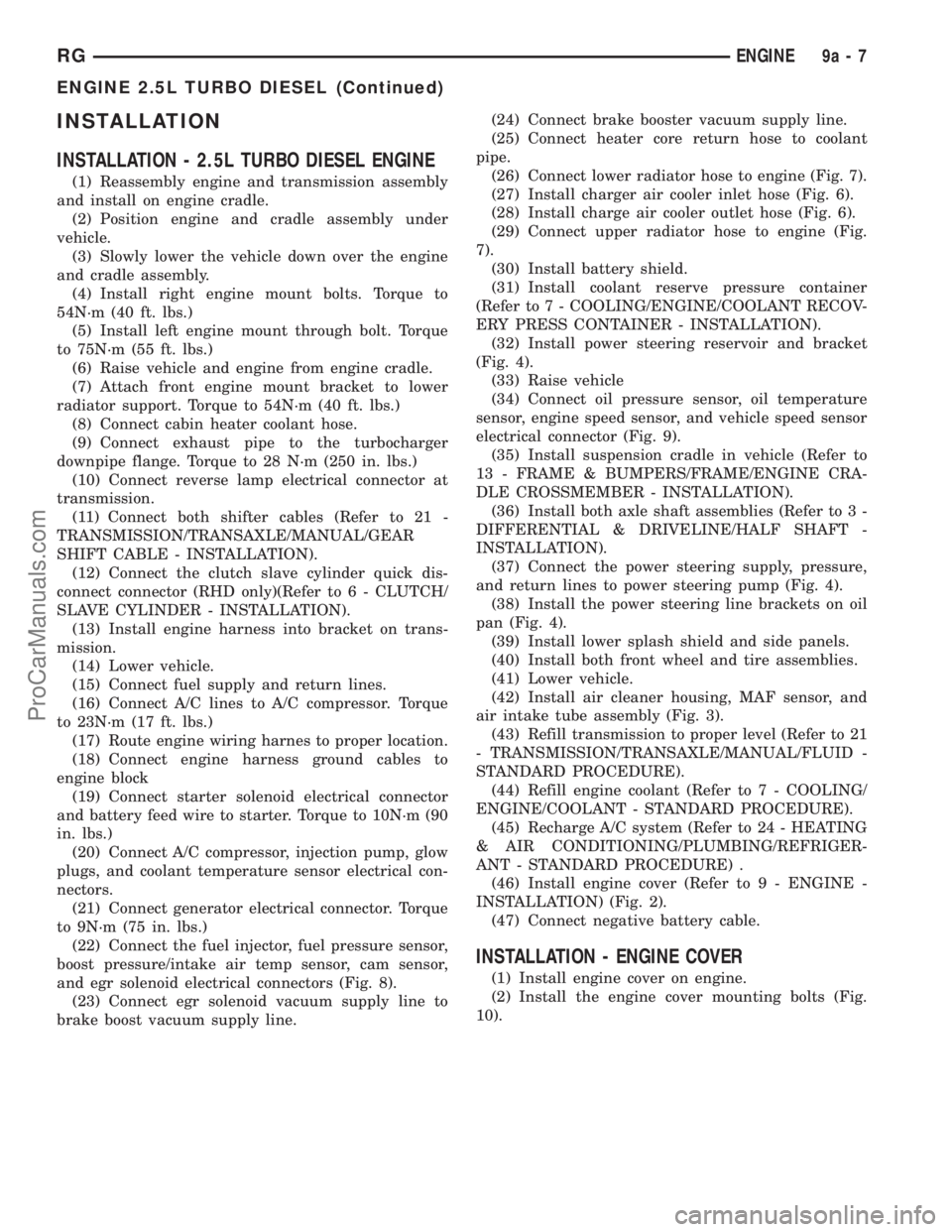
(26) Connect lower radiator hose to engine (Fig. 7).
(27) Install charger air cooler inlet hose (Fig. 6).
(28) Install charge air cooler outlet hose (Fig. 6).
(29) Connect upper radiator hose to engine (Fig.
7).
(30) Install battery shield.
(31) Install coolant reserve pressure container
(Refer to 7 - COOLING/ENGINE/COOLANT RECOV-
ERY PRESS CONTAINER - INSTALLATION).
(32) Install power steering reservoir and bracket
(Fig. 4).
(33) Raise vehicle
(34) Connect oil pressure sensor, oil temperature
sensor, engine speed sensor, and vehicle speed sensor
electrical connector (Fig. 9).
(35) Install suspension cradle in vehicle (Refer to
13 - FRAME & BUMPERS/FRAME/ENGINE CRA-
DLE CROSSMEMBER - INSTALLATION).
(36) Install both axle shaft assemblies (Refer to 3 -
DIFFERENTIAL & DRIVELINE/HALF SHAFT -
INSTALLATION).
(37) Connect the power steering supply, pressure,
and return lines to power steering pump (Fig. 4).
(38) Install the power steering line brackets on oil
pan (Fig. 4).
(39) Install lower splash shield and side panels.
(40) Install both front wheel and tire assemblies.
(41) Lower vehicle.
(42) Install air cleaner housing, MAF sensor, and
air intake tube assembly (Fig. 3).
(43) Refill transmission to proper level (Refer to 21
- TRANSMISSION/TRANSAXLE/MANUAL/FLUID -
STANDARD PROCEDURE).
(44) Refill engine coolant (Refer to 7 - COOLING/
ENGINE/COOLANT - STANDARD PROCEDURE).
(45) Recharge A/C system (Refer to 24 - HEATING
& AIR CONDITIONING/PLUMBING/REFRIGER-
ANT - STANDARD PROCEDURE) .
(46) Install engine cover (Refer to 9 - ENGINE -
INSTALLATION) (Fig. 2).
(47) Connect negative battery cable.
INSTALLATION - ENGINE COVER
(1) Install engine cover on engine.
(2) Install the engine cover mounting bolts (Fig.
10).
RGENGINE9a-7
ENGINE 2.5L TURBO DIESEL (Continued)
ProCarManuals.com
Page 1449 of 2399
REMOVAL
The front cradle crossmember must be installed in
the design location to achieve proper front end sus-
pension alignment. If the cradle crossmember is
removed without applying reference marks on the
frame rails, align the cradle crossmember according
to the dimensions provided in this group.
NOTE: If the caged nuts in the frame rails become
damaged and cannot be reused, a replacement nut
can be obtained through MoparT.
REMOVAL
(1) Disconnect battery negative cable.
(2) Remove steering column lower cover from
instrument panel (Refer to 23 - BODY/INSTRU-
MENT PANEL/STEERING COLUMN OPENING
COVER - REMOVAL).
(3) Remove steering column cover backing plate
(Refer to 23 - BODY/INSTRUMENT PANEL/STEER-
ING COLUMN COVER BACKING PLATE - REMOV-
AL).
(4) Position steering so front wheels are straight
ahead.
CAUTION: Do not rotate steering wheel after disen-
gaging lower coupling from steering gear, damage
to air bag clock spring can result.
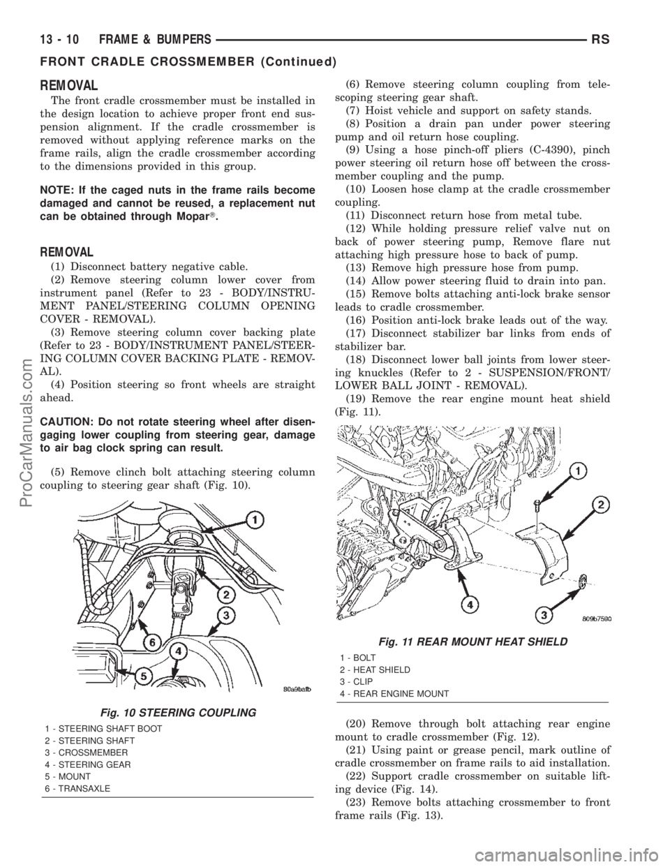
(5) Remove clinch bolt attaching steering column
coupling to steering gear shaft (Fig. 10).(6) Remove steering column coupling from tele-
scoping steering gear shaft.
(7) Hoist vehicle and support on safety stands.
(8) Position a drain pan under power steering
pump and oil return hose coupling.
(9) Using a hose pinch-off pliers (C-4390), pinch
power steering oil return hose off between the cross-
member coupling and the pump.
(10) Loosen hose clamp at the cradle crossmember
coupling.
(11) Disconnect return hose from metal tube.
(12) While holding pressure relief valve nut on
back of power steering pump, Remove flare nut
attaching high pressure hose to back of pump.
(13) Remove high pressure hose from pump.
(14) Allow power steering fluid to drain into pan.
(15) Remove bolts attaching anti-lock brake sensor
leads to cradle crossmember.
(16) Position anti-lock brake leads out of the way.
(17) Disconnect stabilizer bar links from ends of
stabilizer bar.
(18) Disconnect lower ball joints from lower steer-
ing knuckles (Refer to 2 - SUSPENSION/FRONT/
LOWER BALL JOINT - REMOVAL).
(19) Remove the rear engine mount heat shield
(Fig. 11).
(20) Remove through bolt attaching rear engine
mount to cradle crossmember (Fig. 12).
(21) Using paint or grease pencil, mark outline of
cradle crossmember on frame rails to aid installation.
(22) Support cradle crossmember on suitable lift-
ing device (Fig. 14).
(23) Remove bolts attaching crossmember to front
frame rails (Fig. 13).
Fig. 10 STEERING COUPLING
1 - STEERING SHAFT BOOT
2 - STEERING SHAFT
3 - CROSSMEMBER
4 - STEERING GEAR
5 - MOUNT
6 - TRANSAXLE
Fig. 11 REAR MOUNT HEAT SHIELD
1 - BOLT
2 - HEAT SHIELD
3 - CLIP
4 - REAR ENGINE MOUNT
13 - 10 FRAME & BUMPERSRS
FRONT CRADLE CROSSMEMBER (Continued)
ProCarManuals.com
Page 1451 of 2399
INSTALLATION
NOTE: If cradle crossmember requires replacement.
Refer to Group 2, Suspension, to transfer suspen-
sion components and Group 19, Steering, to trans-
fer steering components.
(1) Support crossmember on suitable lifting device
(Fig. 14).
(2) Position crossmember to vehicle.
(3) Loosely install bolts attaching cradle cross-
member to front frame rails.
(4) Align crossmember to previously made marks
on frame rails.
(5) Tighten bolts attaching cradle crossmember to
frame rails.
(6) Install through bolt attaching rear engine
mount to cradle crossmember (Fig. 12) and tighten to
68 N´m (50 ft. lbs.) torque.
(7) Install the rear mount heat shield (Fig. 11).
(8) Connect lower ball joints to steering knuckles
(Refer to 2 - SUSPENSION/FRONT/LOWER BALL
JOINT - INSTALLATION)
(9) Connect stabilizer bar links to ends of stabi-
lizer bar.
(10) Install bolts attaching anti-lock brake sensor
leads to cradle crossmember.
(11) Install high pressure hose to pump.
(12) Connect return hose to metal tube.
(13) Tighten hose clamp at the cradle crossmember
coupling.
(14) Remove pinch-off pliers.
(15) Position steering so front wheels are straight
ahead.
(16) Install steering column coupling to telescoping
steering gear shaft.
(17) Install clinch bolt attaching steering column
coupling to steering gear shaft.
(18) Install steering column cover backing plate
(Refer to 23 - BODY/INSTRUMENT PANEL/STEER-
ING COLUMN COVER BACKING PLATE -
INSTALLATION)
(19) Install steering column lower cover from
instrument panel (Refer to 23 - BODY/INSTRU-MENT PANEL/STEERING COLUMN OPENING
COVER - INSTALLATION).
(20) Connect battery negative cable.
FRONT CROSSMEMBER
MOUNT BUSHINGS
REMOVAL
(1) Using paint or grease pencil, mark outline of
cradle crossmember on frame rails.
(2) Loosen bolts attaching crossmember to frame
rails.
(3) Remove bolt on bushing that requires replace-
ment.
(4) Allow cradle crossmember to drop down enough
to gain clearance for bushing removal.
(5) Remove bushing from vehicle.
INSTALLATION
(1) Apply rubber lubrication or soap to replace-
ment bushing.
(2) Insert lower half of bushing into square hole in
cradle crossmember.
(3) Place upper half of bushing on top of cross-
member aligned to receive square tube protruding
upward from lower bushing half.
(4) Squeeze bushing halves together to ensure they
are properly mated.
(5) Lift cradle crossmember upward to close gap
between the bushing and frame.
(6) Verify that lower bushing is fully seated into
cradle crossmember and upper bushing.
(7) Install bolt attaching bushing and crossmember
to frame rail hand tight.
(8) Align cradle crossmember to reference marks
on frame rails.
(9) Tighten cradle crossmember to frame rails
attaching bolts to 163 N´m (120 ft. lbs.) torque.
13 - 12 FRAME & BUMPERSRS
FRONT CRADLE CROSSMEMBER (Continued)
ProCarManuals.com