relay CHRYSLER VOYAGER 2002 Repair Manual
[x] Cancel search | Manufacturer: CHRYSLER, Model Year: 2002, Model line: VOYAGER, Model: CHRYSLER VOYAGER 2002Pages: 2399, PDF Size: 57.96 MB
Page 508 of 2399
(3) Install the retaining screws.
(4) Reconnect the battery negative cable.
FOG LAMP
DIAGNOSIS AND TESTING - FOG LAMP
When a vehicle experiences problems with the fog
lamp system, verify the condition of the battery con-
nections, fuses, charging system, fog lamp bulbs, wire
connectors, relay, high beam switch, and headlamp
switch. Refer to the appropriate wiring information.
Each vehicle is equipped with various lamp assem-
blies. A good ground is necessary for proper lighting
operation. Grounding is provided by the lamp socket
when it comes in contact with the metal body, or
through a separate ground wire.
When changing lamp bulbs check the socket for
corrosion. If corrosion is present, clean it with a wire
brush.
When it is necessary to remove components to ser-
vice another, it should not be necessary to apply
excessive force or bend a component to remove it.
Before damaging a trim component, verify hidden
fasteners or captured edges are not holding the com-
ponent in place.
FOG LAMP DIAGNOSIS
CONDITION POSSIBLE CAUSES CORRECTION
FOG LAMPS ARE DIM
WITH ENGINE IDLING
OR IGNITION TURNED
OFF.1. Loose or corroded battery
cables.1. Clean and secure battery cable clamps and
posts.
2. Loose or worn generator drive
belt.2. Adjust or replace generator drive belt.
3. Charging system output too low. 3. Test and repair charging system. Refer to
Electrical, Charging,
4. Battery has insufficient charge. 4. Test battery state-of-charge. Refer to
Electrical, Battery System.
5. Battery is sulfated or shorted. 5. Load test battery. Refer to Electrical, Battery
System.
6. Poor lighting circuit Z349/Z248
ground.6. Test for voltage drop across Z349/248
ground locations. Refer to Electrical, Wiring
Information.
FOG LAMP BULBS
BURN OUT
FREQUENTLY1. Charging system output too
high.1. Test and repair charging system. Refer to
Electrical, Charging.
2. Loose or corroded terminals or
splices in circuit.2. Inspect and repair all connectors and splices.
Refer to Electrical, Wiring Information.
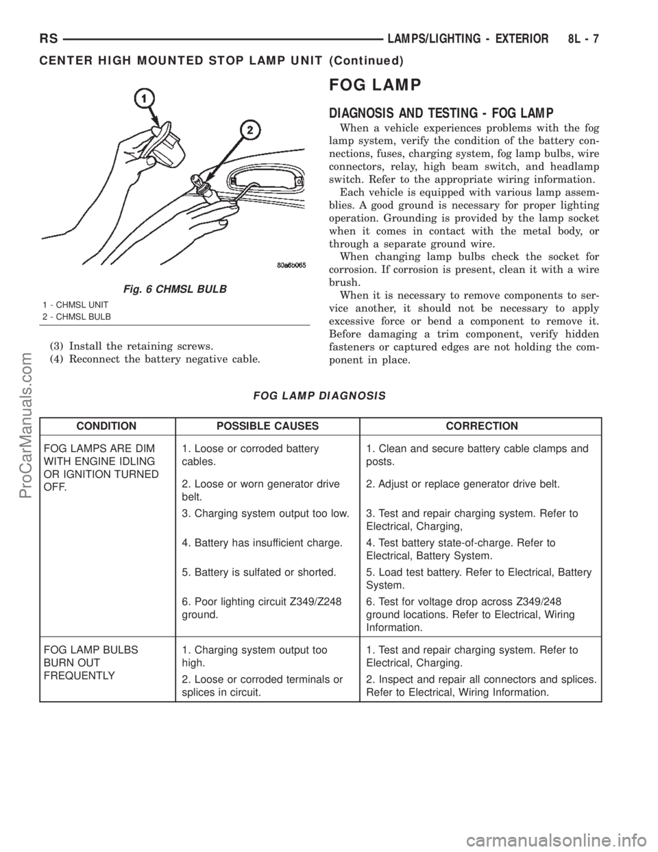
Fig. 6 CHMSL BULB
1 - CHMSL UNIT
2 - CHMSL BULB
RSLAMPS/LIGHTING - EXTERIOR8L-7
CENTER HIGH MOUNTED STOP LAMP UNIT (Continued)
ProCarManuals.com
Page 509 of 2399
CONDITION POSSIBLE CAUSES CORRECTION
FOG LAMPS ARE DIM
WITH ENGINE
RUNNING ABOVE IDLE1. Charging system output too low. 1. Test and repair charging system. Refer to
Electrical, Charging.
2. Poor lighting circuit Z349/Z248
ground.2. Test for voltage drop across Z349/Z248
ground locations. Refer to Electrical, Wiring
Information.
3. High resistance in fog lamp
circuit.3. Test amperage draw of fog lamp circuit.
FOG LAMPS FLASH
RANDOMLY1. Poor lighting circuit Z349/Z248
ground.1. Test for voltage drop across Z349/Z248
ground locations. Refer to Electrical, Wiring
Information.
2. Variable resistance in fog lamp
circuit.2. Test amperage draw of fog lamp circuit.
3. Faulty fog lamp switch (part of
headlamp switch).3. Replace headlamp switch.
4. Loose or corroded terminals or
splices in circuit.4. Inspect and repair all connectors and splices.
Refer to Electrical, Wiring Information.
5. Is relay engaging properly? 5. Verify function of fog lamp relay in IPM.
6. PCI Bus Communication. 6. Verify PCI bus message (fog lamp info)
transmitted from BCM and received by FCM.
FOG LAMPS DO NOT
ILLUMINATE1. Blown fuse for fog lamp. 1. Replace fuse. Refer to Electrical, Wiring
Information.
2. No Z349/Z248 ground at fog
lamps.2. Repair circuit ground. Refer to Electrical,
Wiring Information.
3. Faulty fog lamp switch (part of
headlamp switch).3. Replace headlamp switch.
4. Broken connector terminal or
wire splice in fog lamp circuit.4. Repair connector terminal or wire splice.
5. Faulty or burned out bulb. 5. Replace bulb.
6. Is relay engaging? 6. Verify function of fog lamp relay in IPM.
7. PCI Bus Communication. 7. Verify PCI bus message (fog lamp info)
transmitted from BCM and received by FCM.
8L - 8 LAMPS/LIGHTING - EXTERIORRS
FOG LAMP (Continued)
ProCarManuals.com
Page 513 of 2399
(4) Install the headlamp unit.
(5) Connect the battery negative cable.
HEADLAMP
DIAGNOSIS AND TESTING - HEADLAMP
When a vehicle experiences problems with the
headlamp system, verify the condition of the battery
connections, fuses, charging system, headlamp bulbs,
wire connectors, relay, high beam switch, dimmer
switch, and headlamp switch. Refer to the appropri-
ate wiring information.
Each vehicle is equipped with various lamp assem-
blies. A good ground is necessary for proper lighting
operation. Grounding is provided by the lamp socket
when it comes in contact with the metal body, or
through a separate ground wire.
When changing lamp bulbs check the socket for
corrosion. If corrosion is present, clean it with a wire
brush.
When it is necessary to remove components to ser-
vice another, it should not be necessary to apply
excessive force or bend a component to remove it.
Before damaging a trim component, verify hidden
fasteners or captured edges are not holding the com-
ponent in place.
HEADLAMP DIAGNOSIS
CONDITION POSSIBLE CAUSES CORRECTION
HEADLAMPS ARE DIM
WITH ENGINE IDLING
OR IGNITION TURNED
OFF.1. Loose or corroded battery
cables.1. Clean and secure battery cable clamps and
posts.
2. Loose or worn generator drive
belt.2. Adjust or replace generator drive belt.
3. Charging system output too low. 3. Test and repair charging system, refer to
Electrical, Charging
4. Battery has insufficient charge. 4. Test battery state-of-charge, refer to
Electrical, Battery System.
5. Battery is sulfated or shorted. 5. Load test battery, refer to Electrical, Battery
System.
6. Poor lighting circuit Z343/Z344-
ground.6. Test for voltage drop across Z343/Z344-
ground locations, refer to Electrical, Wiring
Diagram Information.
HEADLAMP BULBS
BURN OUT
FREQUENTLY.1. Integrated Power Module (IPM)
not controlling voltage.1. Test and repair Integrated Power Module.
2. Loose or corroded terminals or
splices in circuit.2. Inspect and repair all connectors and splices.
Refer to Electrical, Wiring Information.
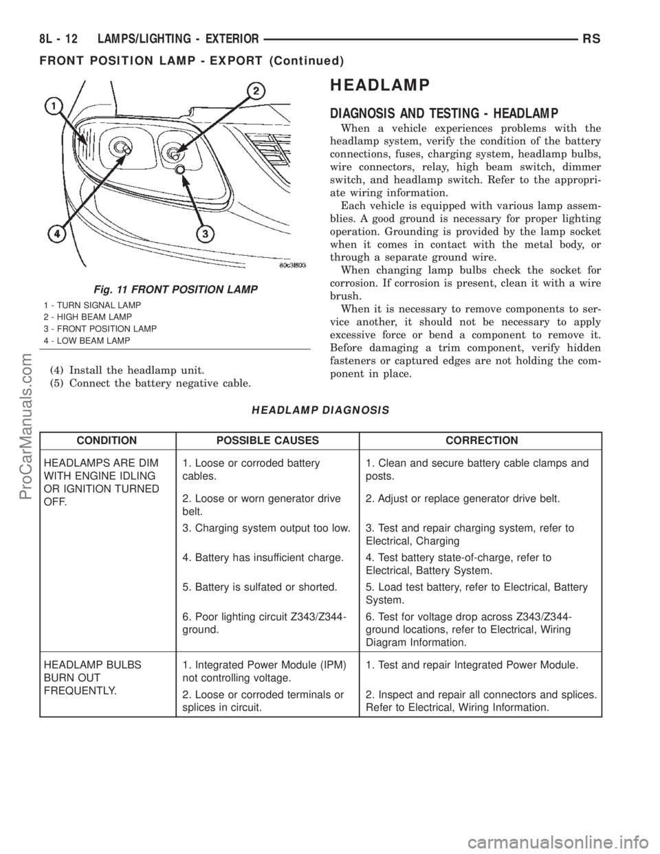
Fig. 11 FRONT POSITION LAMP
1 - TURN SIGNAL LAMP
2 - HIGH BEAM LAMP
3 - FRONT POSITION LAMP
4 - LOW BEAM LAMP
8L - 12 LAMPS/LIGHTING - EXTERIORRS
FRONT POSITION LAMP - EXPORT (Continued)
ProCarManuals.com
Page 591 of 2399
OPERATION
When the mirror retract switch is depressed, both
of the side view mirrors will fold inward, Thus mak-
ing the overall width of the vehicle the smallest pos-
sible. This can be helpful were parking space is a
absolute minimum.
When the driver's door is opened, only the driver's
door mirror will unfold. If the passenger door is
opened, both mirrors will unfold.
The power fold away mirror system consists of the
following components: mirror switch, side view mir-
ror, relay, wires and fuse. Refer to the appropriate
wiring information. The wiring information includes
wiring diagrams, proper wire and connector repair
procedures, details of wire harness routing and
retention, connector pin-out information and location
views for the various wire harness connectors, splices
and grounds.
REMOVAL
(1) Disconnect and isolate the battery negative
cable.
(2) Remove the upper and lower steering column
shroud (Refer to 19 - STEERING/COLUMN/LOWER
SHROUD - REMOVAL).
(3) Disconnect electrical harness connector.
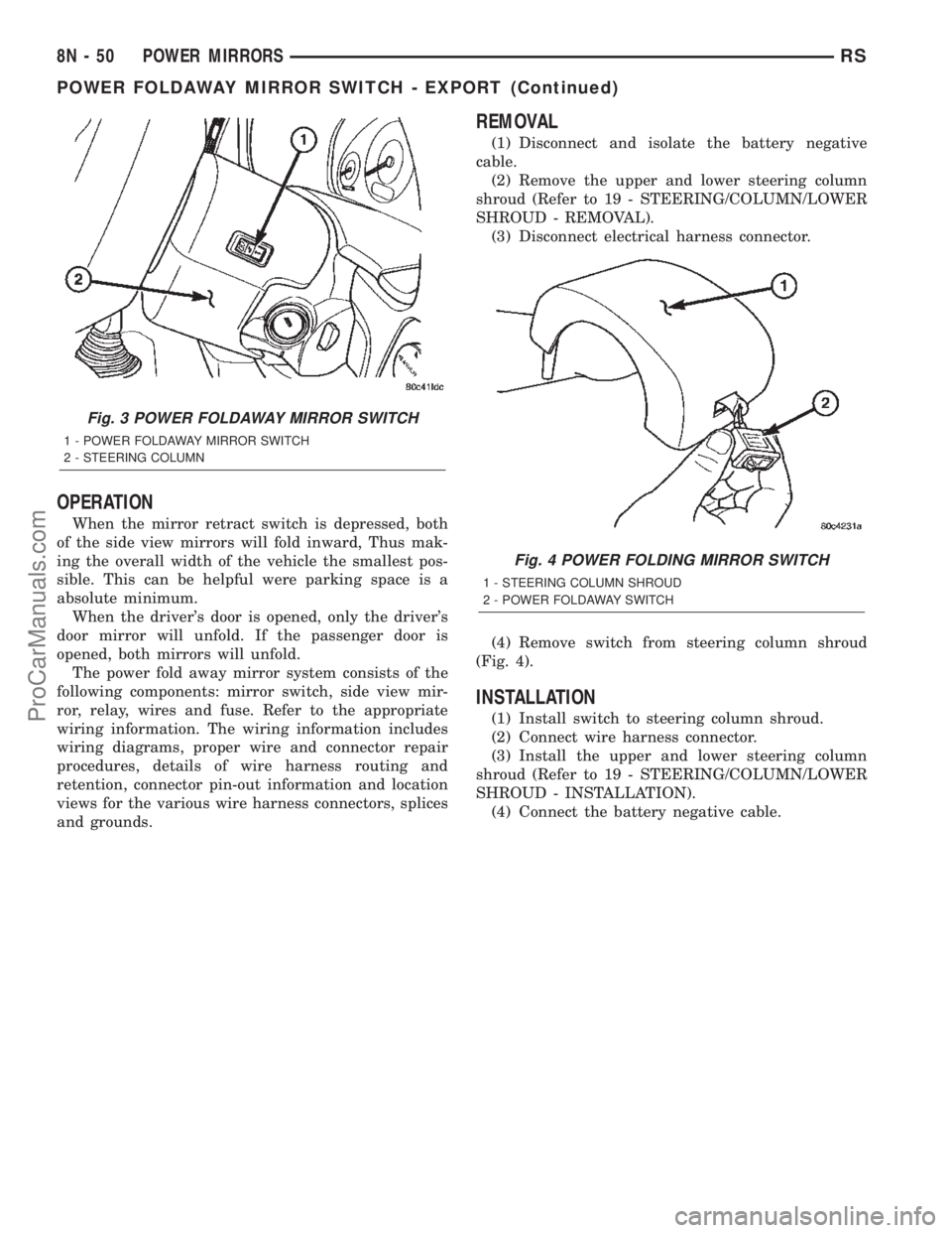
(4) Remove switch from steering column shroud
(Fig. 4).
INSTALLATION
(1) Install switch to steering column shroud.
(2) Connect wire harness connector.
(3) Install the upper and lower steering column
shroud (Refer to 19 - STEERING/COLUMN/LOWER
SHROUD - INSTALLATION).
(4) Connect the battery negative cable.
Fig. 3 POWER FOLDAWAY MIRROR SWITCH
1 - POWER FOLDAWAY MIRROR SWITCH
2 - STEERING COLUMN
Fig. 4 POWER FOLDING MIRROR SWITCH
1 - STEERING COLUMN SHROUD
2 - POWER FOLDAWAY SWITCH
8N - 50 POWER MIRRORSRS
POWER FOLDAWAY MIRROR SWITCH - EXPORT (Continued)
ProCarManuals.com
Page 595 of 2399
system is receiving the proper hard wired inputs and
relaying the proper hard wired outputs to perform its
driver side power seat functions.
WARNING: SOME VEHICLES ARE EQUIPPED WITH
SEATBACK MOUNTED AIRBAGS. BEFORE
ATTEMPTING TO DIAGNOSE OR SERVICE ANY
SEAT OR POWER SEAT SYSTEM COMPONENT
YOU MUST FIRST DISCONNECT AND ISOLATE THE
BATTERY NEGATIVE CABLE. THEN WAIT TWO MIN-
UTES FOR THE SYSTEM CAPACITOR TO DIS-
CHARGE BEFORE FURTHER SYSTEM SERVICE.
THIS IS THE ONLY SURE WAY TO DISABLE THE
AIRBAG SYSTEM. FAILURE TO DO SO COULD
RESULT IN ACCIDENTAL AIRBAG DEPLOYMENT
AND POSSIBLE PERSONAL INJURY.
(1) If the driver power seat exhibits a interrupted
or jerky motion, there is a possibility that the wires
leading from the memory seat module to the memory
seat motor are mis-wired. To check the concern,
obtain a DRB IIItscan tool and energize each axis
one at a time. If any axis stops in approximately 2
seconds (without hitting the end of travel), the feed-
back for that axis may have an open, short or be mis-
wired. Check the wiring to that axis (module to
motor). Fix any wiring problems and retry that axis.
(2) If any power seat is not operational in any
direction, check the power seat circuit breaker,
located under the trailing edge of the appropriate
power seat. Refer to the Power Distribution section of
this service manual for the circuit breaker diagnosis
and testing procedure.
(3) If the power seat circuit breaker is OK, check
for proper 12v and ground connections at the power
seat switch and/or memory seat module. Fix any wir-
ing problems and retry.
(4) Check the power seat system wire harness con-
nections and pins to ensure proper circuit continuity
and ground paths. For complete circuit diagrams,
refer toWiring Diagrams.
(5) With the dome lamp on, apply the power seat
switch in the direction of the failure. If the dome
lamp dims, the seat may be jamming. Check under
and behind the seat for binding or obstructions. If
the dome lamp does not dim, proceed with testing of
the individual components and circuits in the power
seat system.
DIAGNOSIS AND TESTING - MEMORY SYSTEM
In order to obtain conclusive testing of the memory
system, the Programmable Communications Interface
(PCI) data bus network and all of the electronic mod-
ules that provide inputs to, or receive outputs from
the memory system components must be checked.
The most reliable, efficient, and accurate means to
diagnose the memory system requires the use of aDRB IIItscan tool and the proper Diagnostic Proce-
dures manual. The DRB IIItscan tool can provide
confirmation that the PCI data bus is functional, that
all of the electronic modules are sending and receiv-
ing the proper messages on the PCI data bus, and
that the memory system is receiving the proper hard
wired inputs and relaying the proper hard wired out-
puts to perform its functions.
(1) If the driver power seat exhibits a interrupted
or jerky motion, there is a possibility that the wires
leading from the memory seat module to the memory
seat motor are mis-wired. To check the concern,
obtain a DRB IIItscan tool and energize each axis
one at a time. If any axis stops in approximately 2
seconds (without hitting the end of travel), the feed-
back for that axis may have an open, short or be mis-
wired. Check the wiring to that axis (module to
motor). Fix any wiring problems and retry that axis.
Refer to Wiring Diagrams for complete circuit sche-
matic or connector pin-out information.
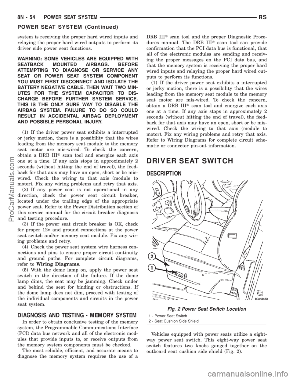
DRIVER SEAT SWITCH
DESCRIPTION
Vehicles equipped with power seats utilize a eight-
way power seat switch. This eight-way power seat
switch features two knobs ganged together on the
outboard seat cushion side shield (Fig. 2).
Fig. 2 Power Seat Switch Location
1 - Power Seat Switch
2 - Seat Cushion Side Shield
8N - 54 POWER SEAT SYSTEMRS
POWER SEAT SYSTEM (Continued)
ProCarManuals.com
Page 608 of 2399
PASSENGER WINDOW SWITCH TEST
SWITCH POSITION CONTINUITY BETWEEN
OFF 3 AND 8
OFF 2 AND 5
UP 1 AND 8
DOWN 1 AND 5
(5) If the results are not OK, replace the switch.
The power window master switch has a Auto-Down
feature. The switch is equipped with two detent posi-
tions when actuating the power window OPEN. The
first detent position allows the window to roll down
and stop when the switch is released. The second
detent position actuates an integral express roll
down relay that rolls the window down after the
switch is released. When the express down circuit
senses stall current (window has reached end of
down travel), the switch will turn current off to the
motor. The AUTO feature can be cancelled by actuat-
ing the switch UP or DOWN while window is in
motion. If the electronic circuit in the switch fails to
detect a stall current, the auto down circuit will time
out within 9 to 13 seconds.
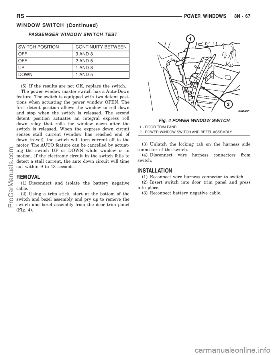
REMOVAL
(1) Disconnect and isolate the battery negative
cable.
(2) Using a trim stick, start at the bottom of the
switch and bezel assembly and pry up to remove the
switch and bezel assembly from the door trim panel
(Fig. 4).(3) Unlatch the locking tab on the harness side
connector of the switch.
(4) Disconnect wire harness connectors from
switch.
INSTALLATION
(1) Reconnect wire harness connector to switch.
(2) Insert switch into door trim panel and press
into place.
(3) Reconnect battery negative cable.
Fig. 4 POWER WINDOW SWITCH
1 - DOOR TRIM PANEL
2 - POWER WINDOW SWITCH AND BEZEL ASSEMBLY
RSPOWER WINDOWS8N-67
WINDOW SWITCH (Continued)
ProCarManuals.com
Page 639 of 2399
OPERATION
FRONT WIPER/WASHER SYSTEM
The windshield washer circuit is protected by a 15
amp Cartridge Fuse located in the IPM. The wiper
motor has permanent magnetic fields. The speeds are
determined by current flow to the appropriate set of
brushes inside the motor. The current flow is con-
trolled by the multi-function switch. The high speed/
low speed relays are located in the IPM. The speed
sensitive intermittent wiper is controlled by the Body
Control Module (BCM). The intermittent mode, with
the vehicle traveling greater than 10.4 mph, has a
range of 0.5 to 18 seconds. With the vehicle traveling
less than 10.4 mph, the time delay doubles to a
range of 1 to 36 seconds. The wiper arms will park at
the base of the windshield just above the cowl cover
after the wiper switch is turned OFF.
The windshield wiper motor and linkage is located
in an integral wiper unit at the rear of the engine
compartment. The wiper unit must be removed to
gain access to the wiper motor.
REAR WIPER/WASHER SYSTEM
When continuous rear wiper operation is required,
the BCM will provide ignition ON voltage to the rear
wiper motor. When the wiper switch is turned OFF,
the BCM provides circuit ground to operate the
motor until the wipe cycle is complete and the wiper
arm returns to the base of the rear window.
When intermittent rear wiper mode is selected, the
wiper motor will cycle every 7 seconds. The intermit-
tent delay time is also adjusted based upon vehicle
speed. With the vehicle traveling greater than 50
mph, the cycle changes to every 5 seconds.
DIAGNOSIS AND TESTING
DIAGNOSIS AND TESTING - FRONT WIPER
SYSTEM
The windshield wiper system operates in several
modes:
²Low and high speed normal wipe²Speed sensitive intermittent wipe
²Wipe after wash
²Park (switch OFF)
The windshield wiper circuits are continuously
monitored and controlled by the Body Control Mod-
ule (BCM). If a problem occurs in the electronic com-
ponents, wiring, switch (except integral motor park
switch) and wiper motor a Diagnostic Trouble Code
(DTC) will be stored in the BCM memory. DTC's can
be retrieved using a DRB IIItscan tool. Refer to the
proper Body Diagnostic Procedures manual for DTC
descriptions and retrieval information.
The windshield wiper park switch and circuit is
monitored by the BCM. The park switch and circuit
can be tested using the Wiper System Diagnosis
table.
DIAGNOSIS AND TESTING - FRONT
WIPER/WASHER SWITCH
(1) Remove the multi-function switch (Refer to 8 -
ELECTRICAL/LAMPS/LIGHTING - EXTERIOR/
MULTI-FUNCTION SWITCH - REMOVAL).
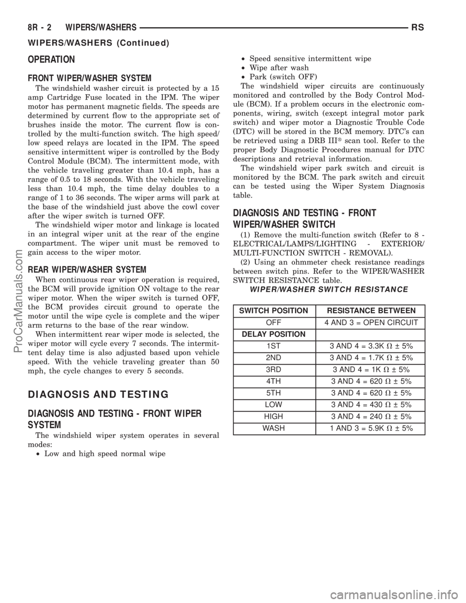
(2) Using an ohmmeter check resistance readings
between switch pins. Refer to the WIPER/WASHER
SWITCH RESISTANCE table.
WIPER/WASHER SWITCH RESISTANCE
SWITCH POSITION RESISTANCE BETWEEN
OFF 4 AND 3 = OPEN CIRCUIT
DELAY POSITION
1ST 3 AND 4 = 3.3KV 5%
2ND 3 AND 4 = 1.7KV 5%
3RD 3AND4=1KV 5%
4TH 3 AND 4 = 620V 5%
5TH 3 AND 4 = 620V 5%
LOW 3 AND 4 = 430V 5%
HIGH 3 AND4=240V 5%
WASH 1 AND 3 = 5.9KV 5%
8R - 2 WIPERS/WASHERSRS
WIPERS/WASHERS (Continued)
ProCarManuals.com
Page 649 of 2399
HEADLAMP WASHER TEST
CONDITION POSSIBLE CAUSE CORRECTION
HEADLAMP WASHER
SYSTEM WILL NOT FLOW
WASHER FLUID.1. NO WASHER FLUID IN
RESERVOIR.1. FILL RESERVOIR.
2. JUNCTION BLOCK FUSE
#5 BLOWN.2. SHORT CIRCUIT BETWEEN JUNCTION BLOCK
FUSE #5 AND WIPER SWITCH TERMINAL #1.
SHORT IN WIPER SWITCH. IF NOT OK, REPAIR
CIRCUIT OR REFER TO WIPER/WASHER
SWITCH DIAGNOSTIC PROCEDURES.
3. HEADLAMP WASHER
HOSE NOT FLOWING FLUID.3. ASSURE WASHER HOSE IS NOT PINCHED,
LOOSE, BROKEN, OR DISCONNECTED. IF NOT
OK, PROPERLY ROUTE OR REPAIR WASHER
HOSE.
4. MOTOR CONNECTOR
LOOSE.4. PROPERLY SEAT CONNECTOR TO MOTOR.
5. MOTOR CONNECTOR
TERMINALS BENT.5. REPAIR TERMINALS AND PROPERLY SEAT
CONNECTOR TO MOTOR.
6. OPEN POWER CIRCUIT
TO SWITCH.6. OPEN OR DEFECTIVE CIRCUIT BETWEEN
JUNCTION BLOCK FUSE #5 AND WASHER
SWITCH CONNECTOR TERMINAL #1. IF NOT OK,
REPAIR CIRCUIT.
7. OPEN OR DEFECTIVE
WIPER/WASHER SWITCH.7. CONNECT AN OHMMETER ACROSS WIPER/
WASHER SWITCH TERMINAL #1 AND #2 AND
DEPRESS WASHER BUTTON AND CHECK FOR
CONTINUITY. IF NOT OK, REFER TO WIPER/
WASHER SWITCH DIAGNOSTIC PROCEDURES.
8. OPEN POWER CIRCUIT
TO MOTOR.8. OPEN OR DEFECTIVE CIRCUIT BETWEEN
WIPER/WASHER SWITCH CONNECTOR
TERMINAL #2 AND MOTOR CONNECTOR
TERMINAL #1. IF NOT OK, REPAIR CIRCUIT.
9. OPEN OR DEFECTIVE
MOTOR GROUND CIRCUIT.9. OPEN OR DEFECTIVE CIRCUIT BETWEEN
WASHER MOTOR CONNECTOR GROUND
TERMINAL #2 AND LEFT HEADLAMP GROUND
#5 OR ENGINE GROUND #1 OR 2.
10. OPEN CIRCUIT IN
HEADLAMP WASHER
MOTOR.10. CHECK FOR AN OPEN CIRCUIT ON MOTOR
BETWEEN POWER TERMINAL #1 AND GROUND
TERMINAL #2. IF NOT OK, REPLACE WASHER
MOTOR.
11. SEIZED MOTOR
BEARINGS.11. APPLY DIRECT BATTERY VOLTAGE TO
MOTOR TERMINALS. IF MOTOR DOES NOT
RUN, REPLACE MOTOR.
12. DEFECTIVE HEADLAMP
WASHER RELAY.12. REPLACE THE HEADLAMP WASHER RELAY.
ONE HEADLAMP WASHER
NOZZLE WILL NOT FLOW
WASHER FLUID.1. HEADLAMP WASHER
HOSE NOT FLOWING FLUID.1. REPAIR OR REPLACE THE HEADLAMP
WASHER HOSE.
2. PLUGGED HEADLAMP
WASHER NOZZLE.2. REPLACE HEADLAMP WASHER NOZZLE.
8R - 12 WIPERS/WASHERSRS
HEADLAMP WASHERS - EXPORT (Continued)
ProCarManuals.com
Page 665 of 2399
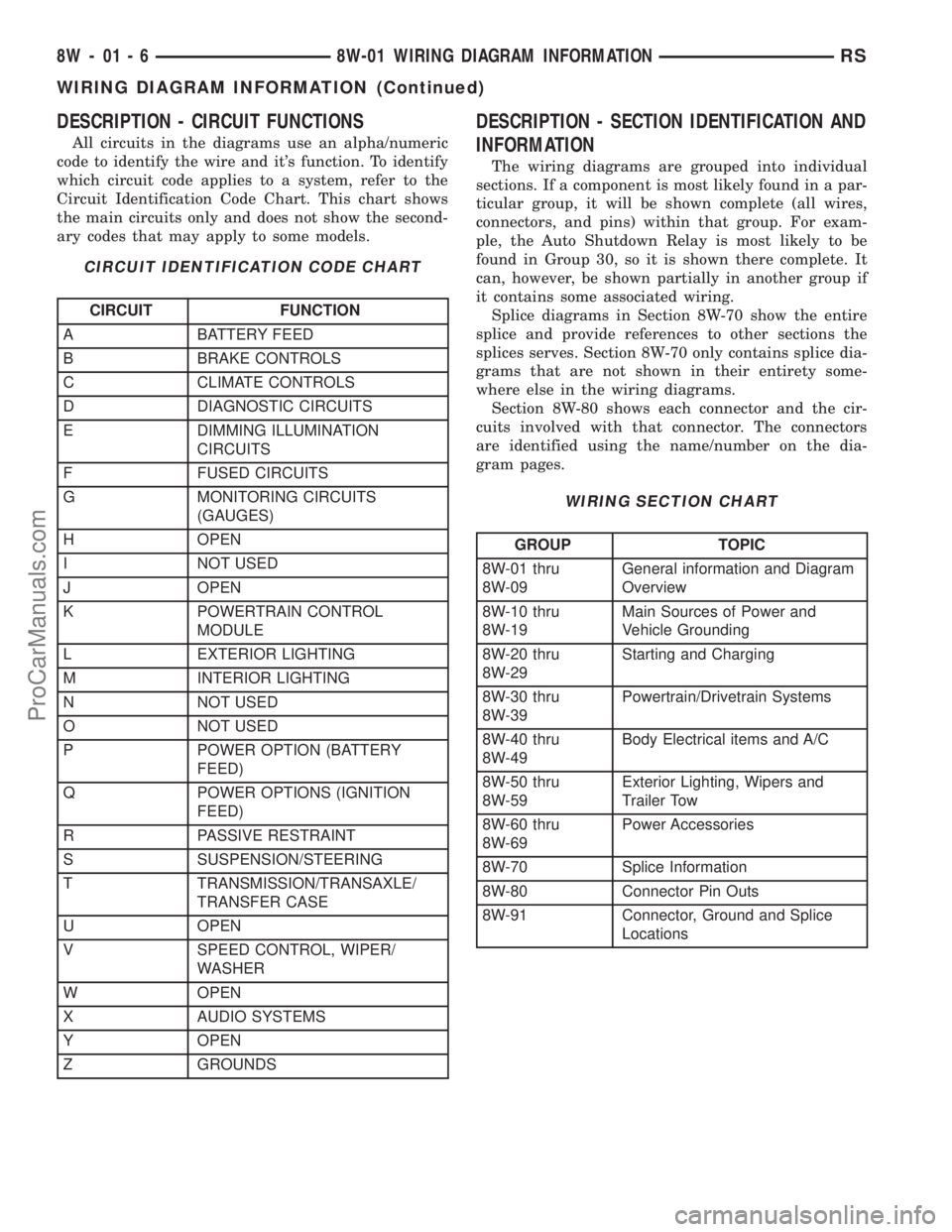
DESCRIPTION - CIRCUIT FUNCTIONS
All circuits in the diagrams use an alpha/numeric
code to identify the wire and it's function. To identify
which circuit code applies to a system, refer to the
Circuit Identification Code Chart. This chart shows
the main circuits only and does not show the second-
ary codes that may apply to some models.
CIRCUIT IDENTIFICATION CODE CHART
CIRCUIT FUNCTION
A BATTERY FEED
B BRAKE CONTROLS
C CLIMATE CONTROLS
D DIAGNOSTIC CIRCUITS
E DIMMING ILLUMINATION
CIRCUITS
F FUSED CIRCUITS
G MONITORING CIRCUITS
(GAUGES)
H OPEN
I NOT USED
J OPEN
K POWERTRAIN CONTROL
MODULE
L EXTERIOR LIGHTING
M INTERIOR LIGHTING
N NOT USED
O NOT USED
P POWER OPTION (BATTERY
FEED)
Q POWER OPTIONS (IGNITION
FEED)
R PASSIVE RESTRAINT
S SUSPENSION/STEERING
T TRANSMISSION/TRANSAXLE/
TRANSFER CASE
U OPEN
V SPEED CONTROL, WIPER/
WASHER
W OPEN
X AUDIO SYSTEMS
Y OPEN
Z GROUNDS
DESCRIPTION - SECTION IDENTIFICATION AND
INFORMATION
The wiring diagrams are grouped into individual
sections. If a component is most likely found in a par-
ticular group, it will be shown complete (all wires,
connectors, and pins) within that group. For exam-
ple, the Auto Shutdown Relay is most likely to be
found in Group 30, so it is shown there complete. It
can, however, be shown partially in another group if
it contains some associated wiring.
Splice diagrams in Section 8W-70 show the entire
splice and provide references to other sections the
splices serves. Section 8W-70 only contains splice dia-
grams that are not shown in their entirety some-
where else in the wiring diagrams.
Section 8W-80 shows each connector and the cir-
cuits involved with that connector. The connectors
are identified using the name/number on the dia-
gram pages.
WIRING SECTION CHART
GROUP TOPIC
8W-01 thru
8W-09General information and Diagram
Overview
8W-10 thru
8W-19Main Sources of Power and
Vehicle Grounding
8W-20 thru
8W-29Starting and Charging
8W-30 thru
8W-39Powertrain/Drivetrain Systems
8W-40 thru
8W-49Body Electrical items and A/C
8W-50 thru
8W-59Exterior Lighting, Wipers and
Trailer Tow
8W-60 thru
8W-69Power Accessories
8W-70 Splice Information
8W-80 Connector Pin Outs
8W-91 Connector, Ground and Splice
Locations
8W - 01 - 6 8W-01 WIRING DIAGRAM INFORMATIONRS
WIRING DIAGRAM INFORMATION (Continued)
ProCarManuals.com
Page 667 of 2399
²Ohmmeter - Used to check the resistance
between two points of a circuit. Low or no resistance
in a circuit means good continuity.
CAUTION: Most of the electrical components used
in today's vehicles are Solid State. When checking
resistance in these circuits use a meter with a 10 -
megohm or greater impedance rating. In addition,
make sure the power is disconnected from the cir-
cuit. Circuits that are powered up by the vehicle's
electrical system can cause damage to the equip-
ment and provide false readings.
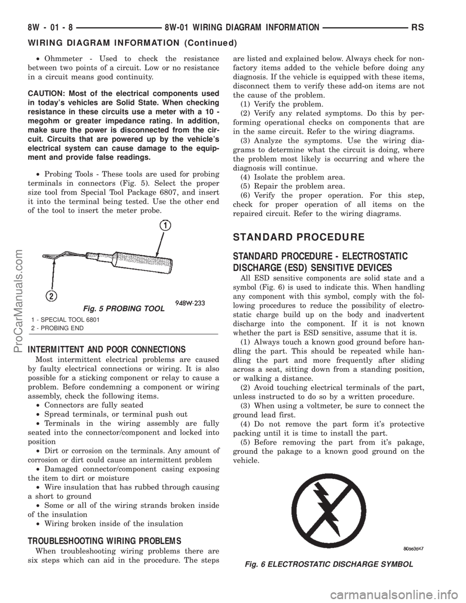
²Probing Tools - These tools are used for probing
terminals in connectors (Fig. 5). Select the proper
size tool from Special Tool Package 6807, and insert
it into the terminal being tested. Use the other end
of the tool to insert the meter probe.
INTERMITTENT AND POOR CONNECTIONS
Most intermittent electrical problems are caused
by faulty electrical connections or wiring. It is also
possible for a sticking component or relay to cause a
problem. Before condemning a component or wiring
assembly, check the following items.
²Connectors are fully seated
²Spread terminals, or terminal push out
²Terminals in the wiring assembly are fully
seated into the connector/component and locked into
position
²
Dirt or corrosion on the terminals. Any amount of
corrosion or dirt could cause an intermittent problem
²Damaged connector/component casing exposing
the item to dirt or moisture
²Wire insulation that has rubbed through causing
a short to ground
²Some or all of the wiring strands broken inside
of the insulation
²Wiring broken inside of the insulation
TROUBLESHOOTING WIRING PROBLEMS
When troubleshooting wiring problems there are
six steps which can aid in the procedure. The stepsare listed and explained below. Always check for non-
factory items added to the vehicle before doing any
diagnosis. If the vehicle is equipped with these items,
disconnect them to verify these add-on items are not
the cause of the problem.
(1) Verify the problem.
(2) Verify any related symptoms. Do this by per-
forming operational checks on components that are
in the same circuit. Refer to the wiring diagrams.
(3) Analyze the symptoms. Use the wiring dia-
grams to determine what the circuit is doing, where
the problem most likely is occurring and where the
diagnosis will continue.
(4) Isolate the problem area.
(5) Repair the problem area.
(6) Verify the proper operation. For this step,
check for proper operation of all items on the
repaired circuit. Refer to the wiring diagrams.
STANDARD PROCEDURE
STANDARD PROCEDURE - ELECTROSTATIC
DISCHARGE (ESD) SENSITIVE DEVICES
All ESD sensitive components are solid state and a
symbol (Fig. 6) is used to indicate this. When handling
any component with this symbol, comply with the fol-
lowing procedures to reduce the possibility of electro-
static charge build up on the body and inadvertent
discharge into the component. If it is not known
whether the part is ESD sensitive, assume that it is.
(1) Always touch a known good ground before han-
dling the part. This should be repeated while han-
dling the part and more frequently after sliding
across a seat, sitting down from a standing position,
or walking a distance.
(2) Avoid touching electrical terminals of the part,
unless instructed to do so by a written procedure.
(3) When using a voltmeter, be sure to connect the
ground lead first.
(4) Do not remove the part form it's protective
packing until it is time to install the part.
(5) Before removing the part from it's pakage,
ground the pakage to a known good ground on the
vehicle.
Fig. 5 PROBING TOOL
1 - SPECIAL TOOL 6801
2 - PROBING END
Fig. 6 ELECTROSTATIC DISCHARGE SYMBOL
8W - 01 - 8 8W-01 WIRING DIAGRAM INFORMATIONRS
WIRING DIAGRAM INFORMATION (Continued)
ProCarManuals.com