charging CHRYSLER VOYAGER 2002 Manual PDF
[x] Cancel search | Manufacturer: CHRYSLER, Model Year: 2002, Model line: VOYAGER, Model: CHRYSLER VOYAGER 2002Pages: 2399, PDF Size: 57.96 MB
Page 1468 of 2399
FUEL INJECTION
OPERATION
OPERATION - INJECTION SYSTEM
All engines used in this section have a sequential
Multi-Port Electronic Fuel Injection system. The MPI
system is computer regulated and provides precise
air/fuel ratios for all driving conditions. The Power-
train Control Module (PCM) operates the fuel injec-
tion system.
The PCM regulates:
²Ignition timing
²Air/fuel ratio
²Emission control devices
²Cooling fan
²Charging system
²Idle speed
²Vehicle speed control
Various sensors provide the inputs necessary for
the PCM to correctly operate these systems. In addi-
tion to the sensors, various switches also provide
inputs to the PCM.
The PCM can adapt its programming to meet
changing operating conditions.
Fuel is injected into the intake port above the
intake valve in precise metered amounts through
electrically operated injectors. The PCM fires the
injectors in a specific sequence. Under most operat-
ing conditions, the PCM maintains an air fuel ratio
of 14.7 parts air to 1 part fuel by constantly adjust-
ing injector pulse width. Injector pulse width is the
length of time the injector is open.
The PCM adjusts injector pulse width by opening
and closing the ground path to the injector. Engine
RPM (speed) and manifold absolute pressure (air
density) are theprimaryinputs that determine
injector pulse width.
OPERATION - MODES OF OPERATION
As input signals to the PCM change, the PCM
adjusts its response to output devices. For example,
the PCM must calculate a different injector pulse
width and ignition timing for idle than it does for
Wide Open Throttle (WOT). There are several differ-
ent modes of operation that determine how the PCM
responds to the various input signals.
There are two different areas of operation, OPEN
LOOP and CLOSED LOOP.
During OPEN LOOP modes the PCM receives
input signals and responds according to preset PCM
programming. Inputs from the upstream and down-
stream heated oxygen sensors are not monitored dur-
ing OPEN LOOP modes, except for heated oxygensensor diagnostics (they are checked for shorted con-
ditions at all times).
During CLOSED LOOP modes the PCM monitors
the inputs from the upstream and downstream
heated oxygen sensors. The upstream heated oxygen
sensor input tells the PCM if the calculated injector
pulse width resulted in the ideal air-fuel ratio of 14.7
to one. By monitoring the exhaust oxygen content
through the upstream heated oxygen sensor, the
PCM can fine tune injector pulse width. Fine tuning
injector pulse width allows the PCM to achieve opti-
mum fuel economy combined with low emissions.
For the PCM to enter CLOSED LOOP operation,
the following must occur:
(1) Engine coolant temperature must be over 35ÉF.
²If the coolant is over 35ÉF the PCM will wait 38
seconds.
²If the coolant is over 50ÉF the PCM will wait 15
seconds.
²If the coolant is over 167ÉF the PCM will wait 3
seconds.
(2) For other temperatures the PCM will interpo-
late the correct waiting time.
(3) O2 sensor must read either greater than 0.745
volts or less than 0.29 volt.
(4) The multi-port fuel injection systems has the
following modes of operation:
²Ignition switch ON (Zero RPM)
²Engine start-up
²Engine warm-up
²Cruise
²Idle
²Acceleration
²Deceleration
²Wide Open Throttle
²Ignition switch OFF
(5) The engine start-up (crank), engine warm-up,
deceleration with fuel shutoff and wide open throttle
modes are OPEN LOOP modes. Under most operat-
ing conditions, the acceleration, deceleration (with
A/C on), idle and cruise modes,with the engine at
operating temperatureare CLOSED LOOP modes.
IGNITION SWITCH ON (ZERO RPM) MODE
When the ignition switch activates the fuel injec-
tion system, the following actions occur:
²The PCM monitors the engine coolant tempera-
ture sensor and throttle position sensor input. The
PCM determines basic fuel injector pulse width from
this input.
²The PCM determines atmospheric air pressure
from the MAP sensor input to modify injector pulse
width.
When the key is in the ON position and the engine
is not running (zero rpm), the Auto Shutdown (ASD)
and fuel pump relays de-energize after approximately
RSFUEL INJECTION14-17
ProCarManuals.com
Page 1479 of 2399
REMOVAL
When servicing throttle body components, always
reassemble components with new O-rings and seals
where applicable. Never use lubricants on O-rings or
seals, damage may result. If assembly of component
is difficult, use water to aid assembly. Use care when
removing hoses to prevent damage to hose or hose
nipple.
(1) Disconnect negative cable from battery.
(2) Remove electrical connector from idle air con-
trol motor.
(3) Remove idle air control motor mounting screws.
(4) Remove motor from throttle body. Ensure the
O-rings is removed with the motor.
INSTALLATION
When servicing throttle body components, always
reassemble components with new O-rings and seals
where applicable. Never use lubricants on O-rings or
seals, damage may result. If assembly of component
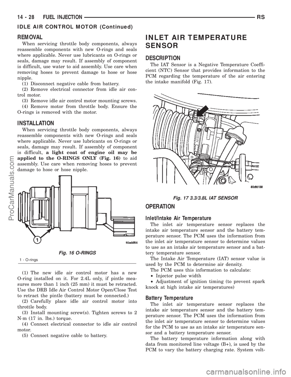
is difficult,a light coat of engine oil may be
applied to the O-RINGS ONLY (Fig. 16)to aid
assembly. Use care when removing hoses to prevent
damage to hose or hose nipple.
(1) The new idle air control motor has a new
O-ring installed on it. For 2.4L only, if pintle mea-
sures more than 1 inch (25 mm) it must be retracted.
Use the DRB Idle Air Control Motor Open/Close Test
to retract the pintle (battery must be connected.)
(2) Carefully place idle air control motor into
throttle body.
(3) Install mounting screw(s). Tighten screws to 2
N´m (17 in. lbs.) torque.
(4) Connect electrical connector to idle air control
motor.
(5) Connect negative cable to battery.
INLET AIR TEMPERATURE
SENSOR
DESCRIPTION
The IAT Sensor is a Negative Temperature Coeffi-
cient (NTC) Sensor that provides information to the
PCM regarding the temperature of the air entering
the intake manifold (Fig. 17).
OPERATION
Inlet/Intake Air Temperature
The inlet air temperature sensor replaces the
intake air temperature sensor and the battery tem-
perature sensor. The PCM uses the information from
the inlet air temperature sensor to determine values
to use as an intake air temperature sensor and a bat-
tery temperature sensor.
The Intake Air Temperature (IAT) sensor value is
used by the PCM to determine air density.
The PCM uses this information to calculate:
²Injector pulse width
²Adjustment of ignition timing (to prevent spark
knock at high intake air temperatures)
Battery Temperature
The inlet air temperature sensor replaces the
intake air temperature sensor and the battery tem-
perature sensor. The PCM uses the information from
the inlet air temperature sensor to determine values
for the PCM to use as an intake air temperature sen-
sor and a battery temperature sensor.
The battery temperature information along with
data from monitored line voltage (B+), is used by the
PCM to vary the battery charging rate. System volt-
Fig. 16 O-RINGS
1 - O-rings
Fig. 17 3.3/3.8L IAT SENSOR
14 - 28 FUEL INJECTIONRS
IDLE AIR CONTROL MOTOR (Continued)
ProCarManuals.com
Page 1496 of 2399
(12) Remove generator (Fig. 11). (Refer to 8 -
ELECTRICAL/CHARGING/GENERATOR -
REMOVAL)
(13) Disconnect fuel supply and return lines at
injection pump (Fig. 11)
(14) Disconnect fuel pressure solenoid electrical
connector at injection pump (Fig. 11)
(15) Remove injection pump retaining nuts.
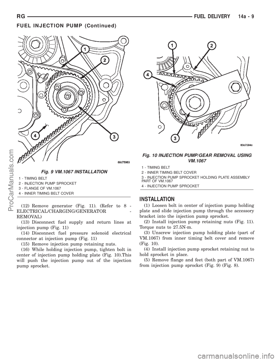
(16) While holding injection pump, tighten bolt in
center of injection pump holding plate (Fig. 10).This
will push the injection pump out of the injection
pump sprocket.
INSTALLATION
(1) Loosen bolt in center of injection pump holding
plate and slide injection pump through the accessory
bracket into the injection pump sprocket.
(2) Install injection pump retaining nuts (Fig. 11).
Torque nuts to 27.5N´m.
(3) Unscrew injection pump holding plate (part of
VM.1067) from inner timing belt cover and remove
(Fig. 10).
(4) Install injection pump sprocket retaining nut to
hold sprocket in place.
(5) Remove flange and feet (both part of VM.1067)
from injection pump sprocket (Fig. 9) (Fig. 8).
Fig. 9 VM.1067 INSTALLATION
1 - TIMING BELT
2 - INJECTION PUMP SPROCKET
3 - FLANGE OF VM.1067
4 - INNER TIMING BELT COVER
Fig. 10 INJECTION PUMP/GEAR REMOVAL USING
VM.1067
1 - TIMING BELT
2 - INNER TIMING BELT COVER
3 - INJECTION PUMP SPROCKET HOLDING PLATE ASSEMBLY
PART OF VM.1067
4 - INJECTION PUMP SPROCKET
RGFUEL DELIVERY14a-9
FUEL INJECTION PUMP (Continued)
ProCarManuals.com
Page 1497 of 2399
(6) Using special tool VM.1055 (Fig. 7), torque
injection pump sprocket retaining nut to 88.3N´m.
(7) Connect fuel pressure solenoid electrical con-
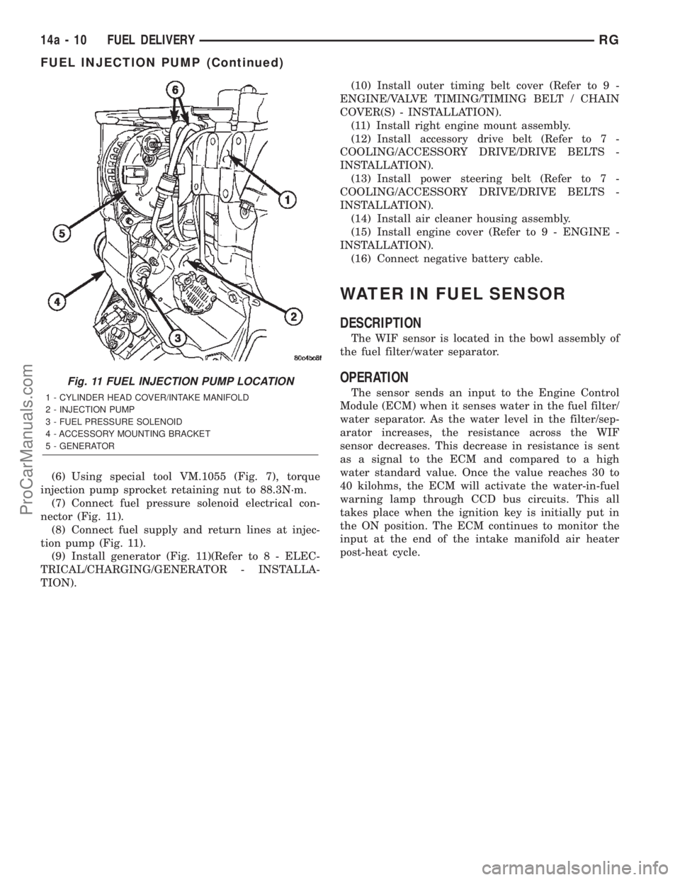
nector (Fig. 11).
(8) Connect fuel supply and return lines at injec-
tion pump (Fig. 11).
(9) Install generator (Fig. 11)(Refer to 8 - ELEC-
TRICAL/CHARGING/GENERATOR - INSTALLA-
TION).(10) Install outer timing belt cover (Refer to 9 -
ENGINE/VALVE TIMING/TIMING BELT / CHAIN
COVER(S) - INSTALLATION).
(11) Install right engine mount assembly.
(12) Install accessory drive belt (Refer to 7 -
COOLING/ACCESSORY DRIVE/DRIVE BELTS -
INSTALLATION).
(13) Install power steering belt (Refer to 7 -
COOLING/ACCESSORY DRIVE/DRIVE BELTS -
INSTALLATION).
(14) Install air cleaner housing assembly.
(15) Install engine cover (Refer to 9 - ENGINE -
INSTALLATION).
(16) Connect negative battery cable.
WATER IN FUEL SENSOR
DESCRIPTION
The WIF sensor is located in the bowl assembly of
the fuel filter/water separator.
OPERATION
The sensor sends an input to the Engine Control
Module (ECM) when it senses water in the fuel filter/
water separator. As the water level in the filter/sep-
arator increases, the resistance across the WIF
sensor decreases. This decrease in resistance is sent
as a signal to the ECM and compared to a high
water standard value. Once the value reaches 30 to
40 kilohms, the ECM will activate the water-in-fuel
warning lamp through CCD bus circuits. This all
takes place when the ignition key is initially put in
the ON position. The ECM continues to monitor the
input at the end of the intake manifold air heater
post-heat cycle.
Fig. 11 FUEL INJECTION PUMP LOCATION
1 - CYLINDER HEAD COVER/INTAKE MANIFOLD
2 - INJECTION PUMP
3 - FUEL PRESSURE SOLENOID
4 - ACCESSORY MOUNTING BRACKET
5 - GENERATOR
14a - 10 FUEL DELIVERYRG
FUEL INJECTION PUMP (Continued)
ProCarManuals.com
Page 2304 of 2399
CAUTION - A/C PLUMBING
CAUTION:: Liquid refrigerant is corrosive to metal
surfaces. Follow the operating instructions supplied
with the service equipment being used.
CAUTION: Never add R-12 to a refrigerant system
designed to use R-134a. Damage to the system will
result.
CAUTION: R-12 refrigerant oil must not be mixed
with R-134a refrigerant oil. They are not compatible.
CAUTION: Do not use R-12 equipment or parts on
the R-134a system. Damage to the system will
result. All parts, tools, and equipment must be
designed for R-134a refrigerant.
CAUTION: Do not discharge refrigerant into the
atmosphere. Use an R-134a refrigerant recovery/re-
cycling device that meets SAE Standard J2210.
CAUTION: The refrigerant must be recovered com-
pletely from the system before opening any fitting
or connection. Open the fittings with caution, even
after the system has been discharged. If any pres-
sure is noticed as a fitting is loosened, tighten the
fitting and recover the refrigerant from the system
again.
CAUTION: The refrigerant system must always be
evacuated before charging.
CAUTION: Do not overcharge the refrigerant sys-
tem. This will cause excessive compressor head
pressure and can cause noise and system failure.
CAUTION: Do not open the refrigerant system or
remove the sealing caps from a replacement com-
ponent until it is to be installed. This will prevent
contamination in the system.
CAUTION: Before disconnecting a component,
clean the outside of the fittings thoroughly to pre-
vent contamination from entering the refrigerant
system.
CAUTION: When it is necessary to open the refrig-
erant system, have everything needed to service
the system ready. Immediately after disconnecting acomponent from the refrigerant system, seal the
open fittings with a cap or plug to prevent the
entrance of dirt and moisture. The refrigerant sys-
tem should not be left open to the atmosphere any
longer than necessary.
CAUTION: Before connecting an open refrigerant
fitting, always install a new seal or gasket. All fit-
tings with O-rings need to be coated with refriger-
ant oil before installation. Use only O-rings that are
the correct size and approved for use with R-134a
refrigerant. Failure to do so may result in a leak.
Coat the fitting and seal with clean refrigerant oil
before connecting. Unified plumbing connections
with gaskets cannot be serviced with O-rings. The
gaskets are not reusable and new gaskets do not
require lubrication before installing.
CAUTION: When installing a refrigerant line, avoid
sharp bends that may restrict refrigerant flow. A
good rule for the flexible hose refrigerant lines is to
keep the radius of all bends at least ten times the
diameter of the hose. Sharp bends will reduce the
flow of refrigerant.
CAUTION: Position the refrigerant lines away from
exhaust system components or any sharp edges,
which may damage the line. The flexible hose lines
should be routed so they are at least 80 millimeters
(3 inches) from the exhaust manifold. Inspect all
flexible refrigerant system hose lines at least once
a year to make sure they are in good condition and
properly routed.
CAUTION: High pressures are produced in the
refrigerant system when it is operating. Extreme
care must be exercised to make sure that all refrig-
erant system connections are pressure tight.
CAUTION: Tighten refrigerant fittings only to the
specified torque. The aluminum fittings used in the
refrigerant system will not tolerate overtightening.
CAUTION: When disconnecting a refrigerant fitting,
use a wrench on both halves of the fitting. This will
prevent twisting of the refrigerant lines or tubes.
CAUTION: Refrigerant oil will absorb moisture from
the atmosphere if left uncapped. Do not open a
container of refrigerant oil until you are ready to
use it. Replace the cap on the oil container immedi-
ately after using. Store refrigerant oil only in a
clean, airtight, and moisture-free container.
RSPLUMBING - FRONT24-61
PLUMBING - FRONT (Continued)
ProCarManuals.com
Page 2314 of 2399
lower half of the door. Tighten the screws to 2 N´m
(18 in. lbs.).
(6) Position the upper intake air housing onto the
top of the evaporator housing over the recirculation
air door and the blower wheel housing. Be certain
that the upper pivot of the recirculation air door is
captured in the pivot receptacle of the upper intake
air housing.
(7) Install and tighten the three screws that secure
the upper intake air housing to the top of the out-
board end of the evaporator housing. Be certain not
to miss the screw located just inside the inboard side
of the fresh air intake opening. Tighten the screws to
2 N´m (18 in. lbs.).
(8) Install and tighten the two screws that secure
the upper intake air housing to the lower intake air
housing. Tighten the screws to 2 N´m (18 in. lbs.).
(9) Engage the two hook formations on the bottom
of the distribution housing in the two receptacles on
the evaporator housing.
(10) Roll the top of the distribution housing up
into position against the evaporator housing.
(11) Install and tighten the three screws from the
dash panel side of the unit that secure the top of the
distribution housing to the inboard end of the evapo-
rator housing. Tighten the screws to 2 N´m (18 in.
lbs.).
(12) Engage the HVAC wire harness in the routing
clips molded into the outside of the HVAC housing
components.
(13) Reconnect the HVAC wire harness connector
for the blower motor with the motor connector recep-
tacle on the bottom of the outboard end of the evap-
orator housing.
(14) Reinstall the expansion valve onto the evapo-
rator inlet and outlet tube fittings. (Refer to 24 -
HEATING & AIR CONDITIONING/PLUMBING -
FRONT/EXPANSION VALVE - INSTALLATION).
(15) Install a new foam seal onto the HVAC hous-
ing seal flange around the fresh air inlet opening and
the expansion valve/evaporator tube opening on the
dash panel side of the unit.
(16) Reinstall the heater core tubes into the heater
core. (Refer to 24 - HEATING & AIR CONDITION-
ING/PLUMBING - FRONT/HEATER CORE -
INSTALLATION - HEATER CORE TUBES).
(17) Reinstall the HVAC unit housing into the
vehicle. (Refer to 24 - HEATING & AIR CONDI-
TIONING/DISTRIBUTION - FRONT/HVAC HOUS-
ING - INSTALLATION).
(18) Run the HVAC Control Actuator Calibration
procedure(Refer to 24 - HEATING & AIR CONDI-
TIONING - DIAGNOSIS AND TESTING)(Refer to 24
- HEATING & AIR CONDITIONING - DIAGNOSIS
AND TESTING).EXPANSION VALVE
DESCRIPTION
The front ªHº valve-type thermal expansion valve
(TXV) is located at the dash panel between the liquid
and suction lines, and the evaporator coil. The
assembly consists of an H-valve body and a thermal
sensor. High-pressure, low temperature liquid refrig-
erant from the liquid line passes through the expan-
sion valve orifice, converting it into a low-pressure,
low-temperature mixture of liquid and gas before it
enters the evaporator coil. The expansion valve is a
factory calibrated unit and cannot be adjusted or
repaired. If faulty or damaged, the expansion valve
must be replaced.
OPERATION
A mechanical sensor in the expansion valve control
head monitors the temperature and pressure of the
refrigerant leaving the evaporator coil through the
suction line, and adjusts the orifice size at the liquid
line to let the proper amount of refrigerant into the
evaporator coil to meet the vehicle cooling require-
ments. Controlling the refrigerant flow through the
evaporator ensures that none of the refrigerant leav-
ing the evaporator is still in a liquid state, which
could damage the compressor. The thermo sensor
measures refrigerant suction gas temperature which
is monitored by the a/c control assembly.
DIAGNOSIS AND TESTING - EXPANSION VALVE
WARNING: REFER TO THE APPLICABLE WARN-
INGS AND CAUTIONS FOR THIS SYSTEM BEFORE
PERFORMING THE FOLLOWING OPERATION.
(Refer to 24 - HEATING & AIR CONDITIONING/
PLUMBING - FRONT - WARNING - A/C PLUMBING)
and (Refer to 24 - HEATING & AIR CONDITIONING/
PLUMBING - FRONT - CAUTION - A/C PLUMBING).
NOTE: The expansion valve should only be tested
following testing of the compressor.
NOTE: Liquid CO is required to test the expansion
valve. This material is available from most welding
supply facilities. Liquid CO is also available from
companies which service and sell fire extinguish-
ers.
When testing the expansion valve, the work area
and the vehicle temperature must be 21É to 27É C
(70É to 85É F). To test the expansion valve:
(1) Connect a charging station or manifold gauge
set to the refrigerant system service ports. Verify the
refrigerant charge level.
RSPLUMBING - FRONT24-71
EVAPORATOR (Continued)
ProCarManuals.com
Page 2330 of 2399

REFRIGERANT
DESCRIPTION
The refrigerant used in this air conditioning sys-
tem is a HydroFluoroCarbon (HFC), type R-134a.
Unlike R-12, which is a ChloroFluoroCarbon (CFC),
R-134a refrigerant does not contain ozone-depleting
chlorine. R-134a refrigerant is a non-toxic, non-flam-
mable, clear, and colorless liquefied gas. Even though
R-134a does not contain chlorine, it must be
reclaimed and recycled just like CFC-type refriger-
ants. This is because R-134a is a greenhouse gas and
can contribute to global warming.
OPERATION
R-134a refrigerant is not compatible with R-12
refrigerant in an air conditioning system. Even a
small amount of R-12 added to an R-134a refrigerant
system will cause compressor failure, refrigerant oil
sludge or poor air conditioning system performance.
In addition, the PolyAlkylene Glycol (PAG) synthetic
refrigerant oils used in an R-134a refrigerant system
are not compatible with the mineral-based refriger-
ant oils used in an R-12 refrigerant system. R-134a
refrigerant system service ports, service tool couplers
and refrigerant dispensing bottles have all been
designed with unique fittings to ensure that an
R-134a system is not accidentally contaminated with
the wrong refrigerant (R-12). There are also labels
posted in the engine compartment of the vehicle and
on the compressor identifying to service technicians
that the air conditioning system is equipped with
R-134a.
DIAGNOSIS AND TESTING
DIAGNOSIS AND TESTING - REFRIGERANT
SYSTEM CHARGE LEVEL
WARNING: REFER TO THE APPLICABLE WARN-
INGS AND CAUTIONS FOR THIS SYSTEM BEFORE
PERFORMING THE FOLLOWING OPERATION.
(Refer to 24 - HEATING & AIR CONDITIONING/
PLUMBING - FRONT - WARNING - A/C PLUMBING)
and (Refer to 24 - HEATING & AIR CONDITIONING/
PLUMBING - FRONT - CAUTION - A/C PLUMBING).
NOTE: The proper amount of R-134a refrigerant for
the refrigerant system in this model is:
²Single or Dual Zone (Front Unit Only) - 0.96
kilograms (2.13 pounds or 34 ounces)
²Three Zone (Front and Rear Units) - 1.31 kilo-
grams (2.88 pounds or 46 ounces)The procedure that follows should be used to deter-
mine whether the refrigerant system contains the
proper refrigerant charge. Symptoms of an improper
refrigerant charge (low) include: poor air conditioner
performance, fog emitted from the air conditioner
outlets, a hissing sound from the expansion valve/
evaporator area. There are two different methods
with which the refrigerant charge level may be
tested:
²Using a DRBIIItscan tool, a thermocouple and
the Charge Determination Chart (Fig. 33). Refer to
the appropriate diagnostic information.
²Using a manifold gauge set, a thermocouple and
the Charge Determination Chart (Fig. 33).
A temperature probe is required to measure liquid
line temperature. The clamp-on, Type K thermocou-
ple temperature probe used in this procedure is
available through the DaimlerChrysler Professional
Service Equipment (PSE) program. This probe (PSE
#66-324-0014 or #80PK-1A) is compatible with tem-
perature-measuring instruments that accept Type K
thermocouples, and have a miniature connector
input. Other temperature probes are available
through aftermarket sources; however, all references
in this procedure will reflect the use of the probe
made available through the PSE program.
In order to use the temperature probe, a digital
thermometer will also be required. If a digital ther-
mometer is not available, an adapter is available
through the PSE program that will convert any stan-
dard digital multimeter into a digital thermometer.
This adapter is designed to accept any standard Type
K thermocouple. If a digital multimeter is not avail-
able, this tool is also available through the PSE pro-
gram.
NOTE: When connecting the service equipment
couplings to the refrigerant system service ports,
be certain that the valve of each coupling is fully
closed. This will reduce the amount of effort
required to make the connection.
(1) Remove the caps from the refrigerant system
service ports and attach a manifold gauge set or a
R-134a refrigerant recovery/recycling/charging sta-
tion that meets SAE Standard J2210 to the refriger-
ant system.
(2) Attach a clamp-on thermocouple to the liquid
line. The thermocouple must be placed as close to the
A/C pressure transducer as possible to accurately
observe liquid line temperature.
(3) Bring the refrigerant system up to operating
temperature and pressure. This is done by allowing
the engine to run at idle under the following condi-
tions for five minutes.
(a) Front windows are open.
(b) Transaxle in Park.
RSPLUMBING - FRONT24-87
ProCarManuals.com
Page 2332 of 2399

location of a possible refrigerant leak, the exact leak
location should be confirmed with an electronic leak
detector prior to component repair or replacement.
An electronic leak detector designed for R-134a
refrigerant is recommended for locating and confirm-
ing refrigerant system leaks. See the operating
instructions supplied by the equipment manufacturer
for proper care and use of this equipment.
To detect a leak in the refrigerant system, perform
one of the following procedures as indicated by the
results of the refrigerant system charge level test.
SYSTEM EMPTY
(1) Evacuate the refrigerant system. (Refer to 24 -
HEATING & AIR CONDITIONING/PLUMBING -
FRONT/REFRIGERANT - STANDARD PROCE-
DURE - REFRIGERANT SYSTEM EVACUATE).
(2) Connect and dispense 0.283 kilograms (0.625
pounds or 10 ounces) of R-134a refrigerant into the
evacuated refrigerant system. (Refer to 24 - HEAT-
ING & AIR CONDITIONING/PLUMBING - FRONT/
REFRIGERANT - STANDARD PROCEDURE -
REFRIGERANT SYSTEM CHARGE).
(3) Proceed to the SYSTEM LOW procedures.
SYSTEM LOW
(1) Position the vehicle in a wind-free work area.
This will aid in detecting small leaks.
(2) Bring the refrigerant system up to operating
temperature and pressure. This is done by allowing
the engine to run at idle under the following condi-
tions for five minutes, then turning the engine off.
(a) Front windows are open.
(b) Rear air conditioner Off (if equipped).
(c) Transaxle in Park.
(d) Front heater-A/C controls set to outside air,
panel mode, blower high, and compressor engaged.
(3) Wait five to seven minutes and, with the
engine not running, use a electronic R-134a leak
detector and search for leaks. Because R-134a refrig-
erant is heavier than air, the leak detector probe
should be moved slowly along the bottom side of all
refrigerant lines, connector fittings and components.
(4) To inspect an evaporator for leaks, insert the
electronic leak detector probe into a floor outlet or
the recirculation air intake.
DIAGNOSIS AND TESTING - REFRIGERANT
SYSTEM CHARGE LEVEL 2.5L DIESEL
WARNING: REFER TO THE APPLICABLE WARN-
INGS AND CAUTIONS FOR THIS SYSTEM BEFORE
PERFORMING THE FOLLOWING OPERATION.
(Refer to 24 - HEATING & AIR CONDITIONING/
PLUMBING - FRONT - WARNING - A/C PLUMBING)and (Refer to 24 - HEATING & AIR CONDITIONING/
PLUMBING - FRONT - CAUTION - A/C PLUMBING).
NOTE: The proper amount of R-134a refrigerant for
the refrigerant system in this model is:
²Single or Dual Zone (Front Unit Only - 2.5L Die-
sel) ± 0.91 kilograms (2.00 pounds or 32 ounces)
²Single or Dual Zone (Front Unit Only) - 0.96
kilograms (2.13 pounds or 34 ounces)
²Three Zone (Front and Rear Units) - 1.31 kilo-
grams (2.88 pounds or 46 ounces)
The procedure that follows should be used to deter-
mine whether the refrigerant system contains the
proper refrigerant charge. Symptoms of an improper
refrigerant charge (low) include: poor air conditioner
performance, fog emitted from the air conditioner
outlets, a hissing sound from the expansion valve/
evaporator area. There are two different methods
with which the refrigerant charge level may be
tested:
²Using a DRBIIItscan tool, a thermocouple and
the Charge Determination Chart (Fig. 34). Refer to
the appropriate diagnostic information.
²Using a manifold gauge set, a thermocouple and
the Charge Determination Chart (Fig. 34).
A temperature probe is required to measure liquid
line temperature. The clamp-on, Type K thermocou-
ple temperature probe used in this procedure is
available through the DaimlerChrysler Professional
Service Equipment (PSE) program. This probe (PSE
#66-324-0014 or #80PK-1A) is compatible with tem-
perature-measuring instruments that accept Type K
thermocouples, and have a miniature connector
input. Other temperature probes are available
through aftermarket sources; however, all references
in this procedure will reflect the use of the probe
made available through the PSE program.
In order to use the temperature probe, a digital
thermometer will also be required. If a digital ther-
mometer is not available, an adapter is available
through the PSE program that will convert any stan-
dard digital multimeter into a digital thermometer.
This adapter is designed to accept any standard Type
K thermocouple. If a digital multimeter is not avail-
able, this tool is also available through the PSE pro-
gram.
NOTE: When connecting the service equipment
couplings to the refrigerant system service ports,
be certain that the valve of each coupling is fully
closed. This will reduce the amount of effort
required to make the connection.
(1) Remove the caps from the refrigerant system
service ports and attach a manifold gauge set or a
R-134a refrigerant recovery/recycling/charging sta-
RSPLUMBING - FRONT24-89
REFRIGERANT (Continued)
ProCarManuals.com
Page 2333 of 2399

tion that meets SAE Standard J2210 to the refriger-
ant system.
(2) Attach a clamp-on thermocouple to the liquid
line. The thermocouple must be placed as close to the
A/C pressure transducer as possible to accurately
observe liquid line temperature.
(3) Bring the refrigerant system up to operating
temperature and pressure. This is done by allowing
the engine to run at idle under the following condi-
tions for five minutes.
(a) Front windows are open.
(b) Transaxle in Park.
(c) Front heater-A/C controls set to outside air,
full cool, panel mode, blower high, and compressor
engaged.
(d) If the vehicle is so equipped, the rear heater-
A/C controls must be set to full cool and blower
high.
(4) Raise the liquid line (discharge) pressure to
about 1793 kPa (260 psi) by placing a piece of card-
board over part of the front side of the condenser. To
place the cardboard properly, remove the upper radi-
ator sight shield from the front fascia. Cover only
enough of the condenser to raise and maintain the
liquid line pressure at the specified level.
(5) Observe the liquid line (discharge) pressure
and liquid line temperature. Using the Charge Deter-
mination Chart (Fig. 34), determine whether therefrigerant system is operating within the Proper
Charge Range.
(a) If the refrigerant system is operating in the
Undercharged area of the chart, add 0.057 kilo-
gram (0.125 pound or 2 ounces) of refrigerant to
the system.
(b) If the refrigerant system is operating in the
Overcharged area of the chart, reclaim 0.057 kilo-
gram (0.125 pound or 2 ounces) of refrigerant from
the system.
(6) Recheck the system charge level following each
refrigerant adjustment. Continue this process until
the system readings are in the Proper Charge Range
area on the Charge Determination Chart (Fig. 34).
STANDARD PROCEDURE
STANDARD PROCEDURE - REFRIGERANT
SYSTEM SERVICE EQUIPMENT
RECOVERY/RECYCLING STATION
When servicing the air conditioning system, a
R-134a refrigerant recovery/recycling/charging sta-
tion that meets SAE Standard J2210 must be used
(Fig. 35). Contact PSE or an automotive service
equipment supplier for refrigerant recovery/recycling/
charging equipment. See the operating instructions
Fig. 34 Charge Determination Chart, Ambient Test Condition 85ÉF
24 - 90 PLUMBING - FRONTRS
REFRIGERANT (Continued)
ProCarManuals.com
Page 2334 of 2399

supplied by the equipment manufacturer for proper
care and use of this equipment.
MANIFOLD GAUGE SET CONNECTIONSCAUTION: Do not use an R-12 manifold gauge set
on an R-134a system. The refrigerants are not com-
patible and system damage will result.
A manifold gauge set may be needed with some
recovery/recycling/charging equipment (Fig. 36). The
service hoses on the gauge set being used should
have manual (turn wheel), or automatic back-flow
valves at the service port connector ends. This will
prevent refrigerant from being released into the
atmosphere.
²LOW PRESSURE GAUGE HOSE- The low
pressure hose (Blue with Black stripe) attaches to
the suction (low side) service port. This port is
located on the suction line, near the compressor at
the front of the engine compartment.
²HIGH PRESSURE GAUGE HOSE- The high
pressure hose (Red with Black stripe) attaches to the
discharge (high side) service port. This port is located
on the liquid line near the filter-drier at the rear of
the engine compartment.
²RECOVERY/RECYCLING/EVACUATION/
CHARGING HOSE- The center manifold hose (Yel-
low, or White, with Black stripe) is used to recover,
evacuate, and charge the refrigerant system. When
the low or high pressure valves on the manifold
gauge set are opened, the refrigerant in the system
will escape through this hose.
STANDARD PROCEDURE - REFRIGERANT
SYSTEM CHARGE
WARNING: REFER TO THE APPLICABLE WARN-
INGS AND CAUTIONS FOR THIS SYSTEM BEFORE
PERFORMING THE FOLLOWING OPERATION.
(Refer to 24 - HEATING & AIR CONDITIONING/
PLUMBING - FRONT - WARNING - A/C PLUMBING)
and (Refer to 24 - HEATING & AIR CONDITIONING/
PLUMBING - FRONT - CAUTION - A/C PLUMBING).
After all refrigerant system leaks have been
repaired and the refrigerant system has been evacu-
ated, a refrigerant charge can be injected into the
system. For the proper amount of the refrigerant
charge, refer to REFRIGERANT CHARGE CAPAC-
ITY . A R-134a refrigerant recovery/recycling/charg-
ing station that meets SAE Standard J2210 must be
used to charge the refrigerant system with R-134a
refrigerant. See the operating instructions supplied
by the equipment manufacturer for proper care and
use of this equipment.
REFRIGERANT CHARGE CAPACITY
The R-134a refrigerant system charge capacity for
this vehicle is:
Fig. 35 Refrigerant Recovery/Recycling Station -
Typical
1 - R-134 REFRIGERANT RECOVERY MACHINE
Fig. 36 Manifold Gauge Set - Typical
1 - HIGH PRESSURE GAUGE
2 - VALVE
3 - VACUUM/REFRIGERANT HOSE (YELLOW W/BLACK STRIPE)
4 - HIGH PRESSURE HOSE (RED W/BLACK STRIPE)
5 - LOW PRESSURE HOSE (BLUE W/BLACK STRIPE)
6 - VALVE
7 - LOW PRESSURE GAUGE
RSPLUMBING - FRONT24-91
REFRIGERANT (Continued)
ProCarManuals.com