clock CHRYSLER VOYAGER 2002 Manual Online
[x] Cancel search | Manufacturer: CHRYSLER, Model Year: 2002, Model line: VOYAGER, Model: CHRYSLER VOYAGER 2002Pages: 2399, PDF Size: 57.96 MB
Page 1356 of 2399
(3) Position heat shield on manifold (Fig. 136).
(4) Install the remaining manifold attaching bolts.
Tighten all bolts to 23 N´m (200 in. lbs.).
(5) Install and tighten heat shield attaching nut to
12 N´m (105 in. lbs.) (Fig. 136).
(6) Connect battery negative cable.
VALVE TIMING
STANDARD PROCEDURE
STANDARD PROCEDURE - VALVE TIMING
VERIFICATION
(1) Remove front cylinder head cover and all 6
spark plugs.
(2) Rotate engine until the #2 piston is at TDC of
the compression stroke.
(3) Install a degree wheel on the crankshaft pulley.
(4) With proper adaptor, install a dial indicator
into #2 spark plug hole. Using the indicator find TDC
on the compression stroke.
(5) Position the degree wheel to zero.
(6) Remove dial indicator from spark plug hole.
(7) Place a 5.08 mm (0.200 in.) spacer between the
valve stem tip of #2 intake valve and rocker arm pad.
Allow tappet to bleed down to give a solid tappet
effect.
(8) Install a dial indicator so plunger contacts the
#2 intake valve spring retainer as nearly perpendic-
ular as possible. Zero the indicator.
(9) Rotate the engine clockwise until the intake
valve has lifted .254 mm (0.010 in.).
CAUTION: Do not turn crankshaft any further clock-
wise as intake valve might bottom and result in
serious damage.
(10) Degree wheel should read 6 degrees BTDC to
6 degrees ATDC.
STANDARD PROCEDURE - MEASURING
TIMING CHAIN WEAR
NOTE: This procedure must be performed with the
timing chain cover removed (Refer to 9 - ENGINE/
VALVE TIMING/TIMING CHAIN COVER - REMOVAL).
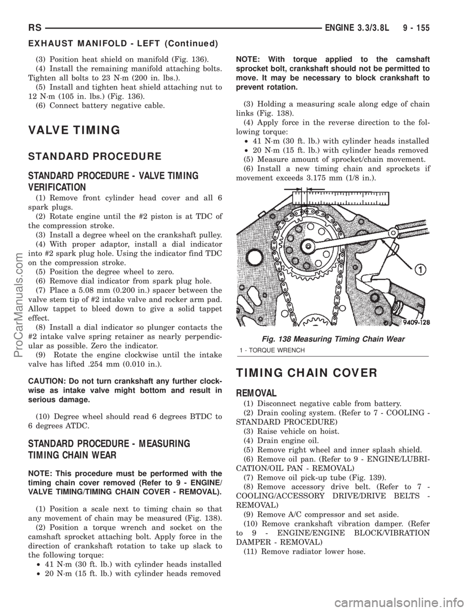
(1) Position a scale next to timing chain so that
any movement of chain may be measured (Fig. 138).
(2) Position a torque wrench and socket on the
camshaft sprocket attaching bolt. Apply force in the
direction of crankshaft rotation to take up slack to
the following torque:
²41 N´m (30 ft. lb.) with cylinder heads installed
²20 N´m (15 ft. lb.) with cylinder heads removedNOTE: With torque applied to the camshaft
sprocket bolt, crankshaft should not be permitted to
move. It may be necessary to block crankshaft to
prevent rotation.
(3) Holding a measuring scale along edge of chain
links (Fig. 138).
(4) Apply force in the reverse direction to the fol-
lowing torque:
²41 N´m (30 ft. lb.) with cylinder heads installed
²20 N´m (15 ft. lb.) with cylinder heads removed
(5) Measure amount of sprocket/chain movement.
(6) Install a new timing chain and sprockets if
movement exceeds 3.175 mm (1/8 in.).
TIMING CHAIN COVER
REMOVAL
(1) Disconnect negative cable from battery.
(2) Drain cooling system. (Refer to 7 - COOLING -
STANDARD PROCEDURE)
(3) Raise vehicle on hoist.
(4) Drain engine oil.
(5) Remove right wheel and inner splash shield.
(6) Remove oil pan. (Refer to 9 - ENGINE/LUBRI-
CATION/OIL PAN - REMOVAL)
(7) Remove oil pick-up tube (Fig. 139).
(8) Remove accessory drive belt. (Refer to 7 -
COOLING/ACCESSORY DRIVE/DRIVE BELTS -
REMOVAL)
(9) Remove A/C compressor and set aside.
(10) Remove crankshaft vibration damper. (Refer
to 9 - ENGINE/ENGINE BLOCK/VIBRATION
DAMPER - REMOVAL)
(11) Remove radiator lower hose.
Fig. 138 Measuring Timing Chain Wear
1 - TORQUE WRENCH
RSENGINE 3.3/3.8L9 - 155
EXHAUST MANIFOLD - LEFT (Continued)
ProCarManuals.com
Page 1360 of 2399
TIMING CHAIN AND
SPROCKETS
REMOVAL
REMOVAL - TIMING CHAIN AND CAMSHAFT
SPROCKET
(1) Disconnect negative cable from battery.
(2) Remove the timing chain cover. (Refer to 9 -
ENGINE/VALVE TIMING/TIMING BELT / CHAIN
COVER(S) - REMOVAL)
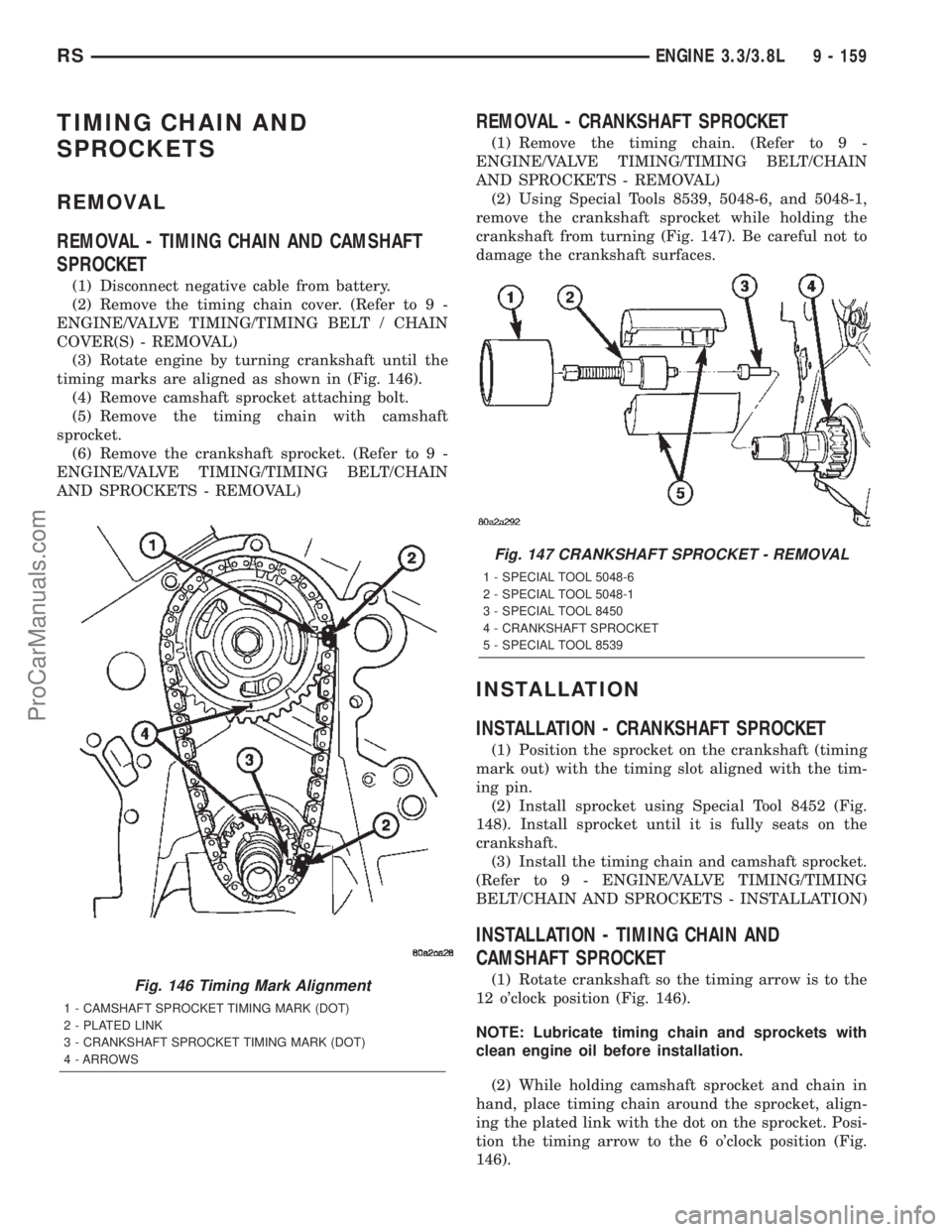
(3) Rotate engine by turning crankshaft until the
timing marks are aligned as shown in (Fig. 146).
(4) Remove camshaft sprocket attaching bolt.
(5) Remove the timing chain with camshaft
sprocket.
(6) Remove the crankshaft sprocket. (Refer to 9 -
ENGINE/VALVE TIMING/TIMING BELT/CHAIN
AND SPROCKETS - REMOVAL)
REMOVAL - CRANKSHAFT SPROCKET
(1) Remove the timing chain. (Refer to 9 -
ENGINE/VALVE TIMING/TIMING BELT/CHAIN
AND SPROCKETS - REMOVAL)
(2) Using Special Tools 8539, 5048-6, and 5048-1,
remove the crankshaft sprocket while holding the
crankshaft from turning (Fig. 147). Be careful not to
damage the crankshaft surfaces.
INSTALLATION
INSTALLATION - CRANKSHAFT SPROCKET
(1) Position the sprocket on the crankshaft (timing
mark out) with the timing slot aligned with the tim-
ing pin.
(2) Install sprocket using Special Tool 8452 (Fig.
148). Install sprocket until it is fully seats on the
crankshaft.
(3) Install the timing chain and camshaft sprocket.
(Refer to 9 - ENGINE/VALVE TIMING/TIMING
BELT/CHAIN AND SPROCKETS - INSTALLATION)
INSTALLATION - TIMING CHAIN AND
CAMSHAFT SPROCKET
(1) Rotate crankshaft so the timing arrow is to the
12 o'clock position (Fig. 146).
NOTE: Lubricate timing chain and sprockets with
clean engine oil before installation.
(2) While holding camshaft sprocket and chain in
hand, place timing chain around the sprocket, align-
ing the plated link with the dot on the sprocket. Posi-
tion the timing arrow to the 6 o'clock position (Fig.
146).Fig. 146 Timing Mark Alignment
1 - CAMSHAFT SPROCKET TIMING MARK (DOT)
2 - PLATED LINK
3 - CRANKSHAFT SPROCKET TIMING MARK (DOT)
4 - ARROWS
Fig. 147 CRANKSHAFT SPROCKET - REMOVAL
1 - SPECIAL TOOL 5048-6
2 - SPECIAL TOOL 5048-1
3 - SPECIAL TOOL 8450
4 - CRANKSHAFT SPROCKET
5 - SPECIAL TOOL 8539
RSENGINE 3.3/3.8L9 - 159
ProCarManuals.com
Page 1363 of 2399
INSTALLATION
INSTALLATION.......................47
INSTALLATION.......................48
OIL PRESSURE SENSOR/SWITCH
DESCRIPTION.........................48
REMOVAL.............................48
INSTALLATION.........................48
OIL TEMPERATURE SENSOR
DESCRIPTION.........................48
REMOVAL.............................48
INSTALLATION.........................48
OIL PRESSURE RELIEF VALVE
DESCRIPTION.........................49
REMOVAL.............................49
INSTALLATION.........................49
OIL COOLER & LINES
REMOVAL.............................50
INSTALLATION.........................50
OIL FILTER
DESCRIPTION.........................51
REMOVAL.............................51
INSTALLATION.........................51
OIL JET
DESCRIPTION.........................52
REMOVAL.............................52
INSTALLATION.........................52
INTAKE MANIFOLD
DESCRIPTION.........................52
REMOVAL.............................52INSTALLATION.........................52
VALVE TIMING
STANDARD PROCEDURE - LOCKING ENGINE
90É AFTER TDC.......................53
BALANCE SHAFT
DESCRIPTION.........................54
OPERATION...........................54
REMOVAL.............................55
INSTALLATION.........................55
TIMING BELT / CHAIN COVER(S)
REMOVAL
REMOVAL - TIMING BELT OUTER COVER . . 56
REMOVAL - TIMING BELT INNER COVER . . . 56
INSTALLATION
INSTALLATION - TIMING BELT OUTER
COVER.............................56
INSTALLATION - TIMING BELT INNER
COVER.............................57
TIMING BELT IDLER PULLEY
REMOVAL.............................58
INSTALLATION.........................58
TMNG BELT/CHAIN TENSIONER
REMOVAL.............................59
INSTALLATION.........................59
ADJUSTMENTS
ADJUSTMENT - TIMING BELT TENSIONER . 60
TIMING BELT/CHAIN AND SPROCKETS
REMOVAL.............................60
INSTALLATION.........................61
ENGINE 2.5L TURBO DIESEL
DESCRIPTION
DESCRIPTION - 2.5L COMMON RAIL DIESEL
ENGINE
This 2.5 Liter (2500cc) four-cylinder ªcommon railº
direct injection engine is an in-line overhead valve
diesel engine. This engine utilizes a cast iron cylin-
der block and an aluminum cylinder head. The
engine is turbocharged and intercooled. The engine
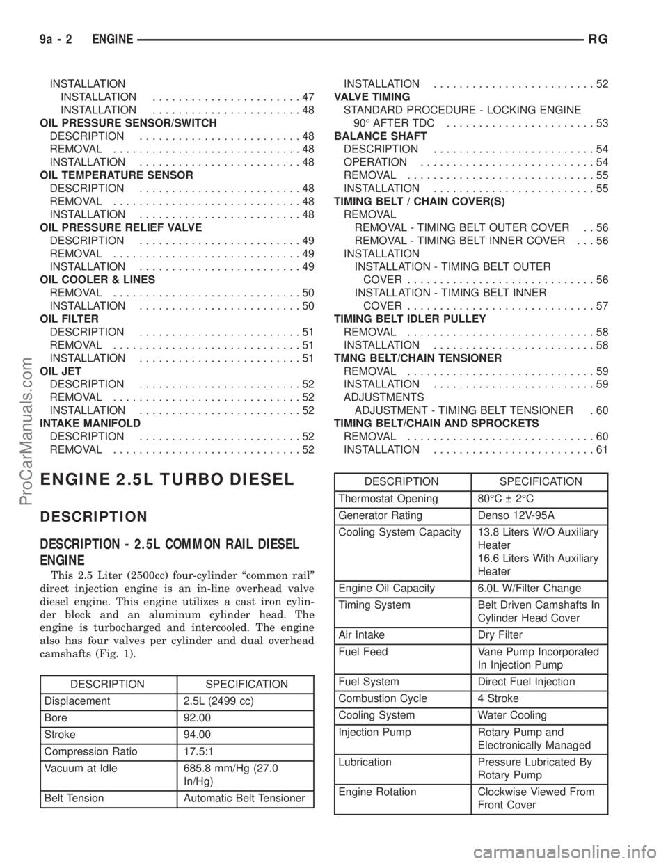
also has four valves per cylinder and dual overhead
camshafts (Fig. 1).
DESCRIPTION SPECIFICATION
Displacement 2.5L (2499 cc)
Bore 92.00
Stroke 94.00
Compression Ratio 17.5:1
Vacuum at Idle 685.8 mm/Hg (27.0
In/Hg)
Belt Tension Automatic Belt Tensioner
DESCRIPTION SPECIFICATION
Thermostat Opening 80ÉC 2ÉC
Generator Rating Denso 12V-95A
Cooling System Capacity 13.8 Liters W/O Auxiliary
Heater
16.6 Liters With Auxiliary
Heater
Engine Oil Capacity 6.0L W/Filter Change
Timing System Belt Driven Camshafts In
Cylinder Head Cover
Air Intake Dry Filter
Fuel Feed Vane Pump Incorporated
In Injection Pump
Fuel System Direct Fuel Injection
Combustion Cycle 4 Stroke
Cooling System Water Cooling
Injection Pump Rotary Pump and
Electronically Managed
Lubrication Pressure Lubricated By
Rotary Pump
Engine Rotation Clockwise Viewed From
Front Cover
9a - 2 ENGINERG
ProCarManuals.com
Page 1449 of 2399
REMOVAL
The front cradle crossmember must be installed in
the design location to achieve proper front end sus-
pension alignment. If the cradle crossmember is
removed without applying reference marks on the
frame rails, align the cradle crossmember according
to the dimensions provided in this group.
NOTE: If the caged nuts in the frame rails become
damaged and cannot be reused, a replacement nut
can be obtained through MoparT.
REMOVAL
(1) Disconnect battery negative cable.
(2) Remove steering column lower cover from
instrument panel (Refer to 23 - BODY/INSTRU-
MENT PANEL/STEERING COLUMN OPENING
COVER - REMOVAL).
(3) Remove steering column cover backing plate
(Refer to 23 - BODY/INSTRUMENT PANEL/STEER-
ING COLUMN COVER BACKING PLATE - REMOV-
AL).
(4) Position steering so front wheels are straight
ahead.
CAUTION: Do not rotate steering wheel after disen-
gaging lower coupling from steering gear, damage
to air bag clock spring can result.
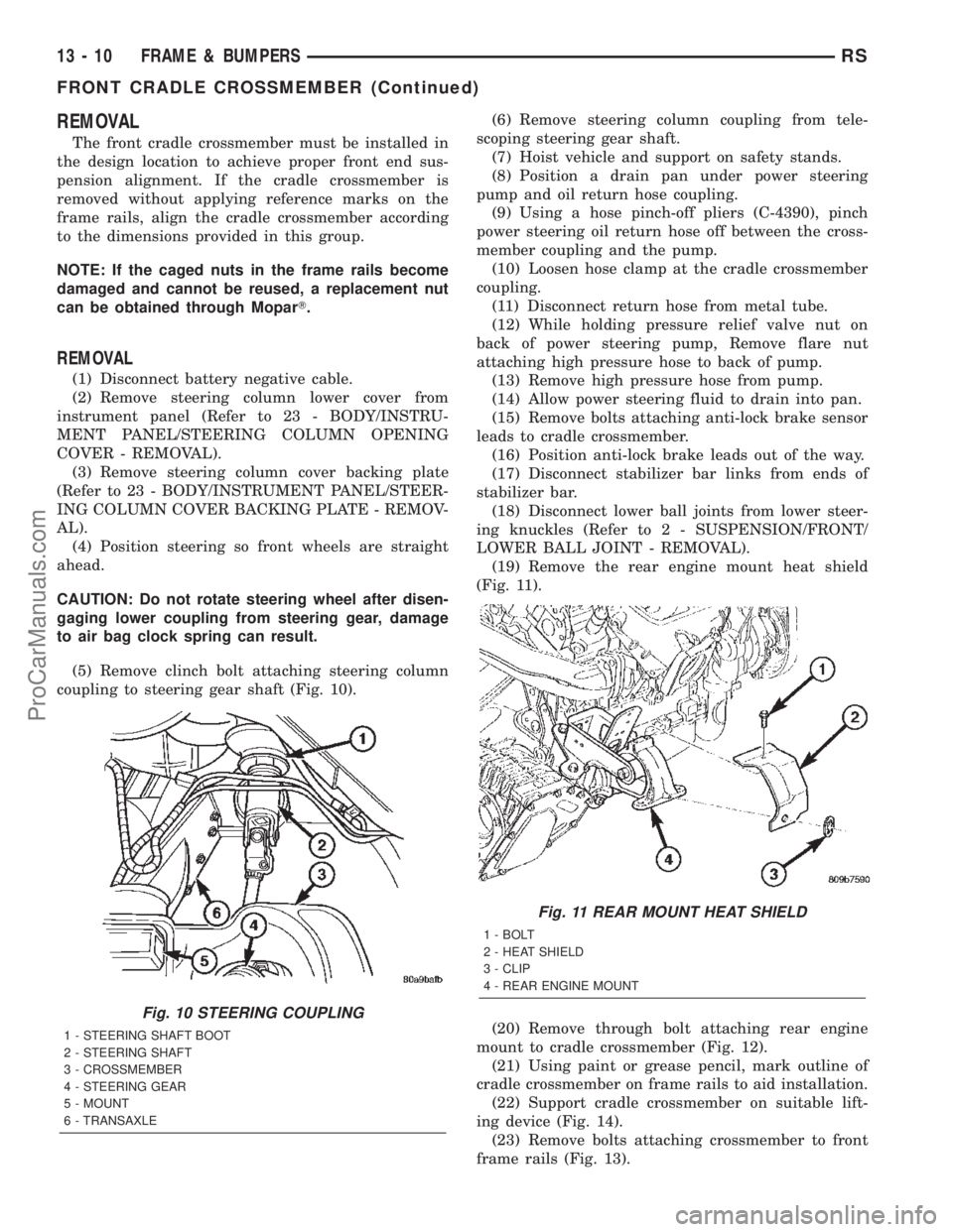
(5) Remove clinch bolt attaching steering column
coupling to steering gear shaft (Fig. 10).(6) Remove steering column coupling from tele-
scoping steering gear shaft.
(7) Hoist vehicle and support on safety stands.
(8) Position a drain pan under power steering
pump and oil return hose coupling.
(9) Using a hose pinch-off pliers (C-4390), pinch
power steering oil return hose off between the cross-
member coupling and the pump.
(10) Loosen hose clamp at the cradle crossmember
coupling.
(11) Disconnect return hose from metal tube.
(12) While holding pressure relief valve nut on
back of power steering pump, Remove flare nut
attaching high pressure hose to back of pump.
(13) Remove high pressure hose from pump.
(14) Allow power steering fluid to drain into pan.
(15) Remove bolts attaching anti-lock brake sensor
leads to cradle crossmember.
(16) Position anti-lock brake leads out of the way.
(17) Disconnect stabilizer bar links from ends of
stabilizer bar.
(18) Disconnect lower ball joints from lower steer-
ing knuckles (Refer to 2 - SUSPENSION/FRONT/
LOWER BALL JOINT - REMOVAL).
(19) Remove the rear engine mount heat shield
(Fig. 11).
(20) Remove through bolt attaching rear engine
mount to cradle crossmember (Fig. 12).
(21) Using paint or grease pencil, mark outline of
cradle crossmember on frame rails to aid installation.
(22) Support cradle crossmember on suitable lift-
ing device (Fig. 14).
(23) Remove bolts attaching crossmember to front
frame rails (Fig. 13).
Fig. 10 STEERING COUPLING
1 - STEERING SHAFT BOOT
2 - STEERING SHAFT
3 - CROSSMEMBER
4 - STEERING GEAR
5 - MOUNT
6 - TRANSAXLE
Fig. 11 REAR MOUNT HEAT SHIELD
1 - BOLT
2 - HEAT SHIELD
3 - CLIP
4 - REAR ENGINE MOUNT
13 - 10 FRAME & BUMPERSRS
FRONT CRADLE CROSSMEMBER (Continued)
ProCarManuals.com
Page 1508 of 2399
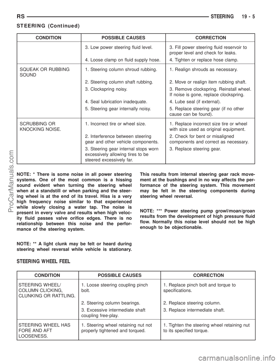
CONDITION POSSIBLE CAUSES CORRECTION
3. Low power steering fluid level. 3. Fill power steering fluid reservoir to
proper level and check for leaks.
4. Loose clamp on fluid supply hose. 4. Tighten or replace hose clamp.
SQUEAK OR RUBBING
SOUND1. Steering column shroud rubbing. 1. Realign shrouds as necessary.
2. Steering column shaft rubbing. 2. Move or realign item rubbing shaft.
3. Clockspring noisy. 3. Remove clockspring. Reinstall wheel.
If noise is gone, replace clockspring.
4. Seal lubrication inadequate. 4. Lube seal (if external).
5. Steering gear internally noisy. 5. Replace steering gear (if no other
cause can be found).
SCRUBBING OR
KNOCKING NOISE.1. Incorrect tire or wheel size. 1. Replace incorrect size tire or wheel
with size used as original equipment.
2. Interference between steering
gear and other vehicle components.2. Check for bent or misaligned
components and correct as necessary.
3. Steering gear internal stops worn
excessively allowing tires to be
steered excessively far.3. Replace steering gear.
NOTE: * There is some noise in all power steering
systems. One of the most common is a hissing
sound evident when turning the steering wheel
when at a standstill or when parking and the steer-
ing wheel is at the end of its travel. Hiss is a very
high frequency noise similar to that experienced
while slowly closing a water tap. The noise is
present in every valve and results when high veloc-
ity fluid passes valve orifice edges. There is no
relationship between this noise and the perfor-
mance of the steering system.
NOTE: ** A light clunk may be felt or heard during
steering wheel reversal while vehicle is stationary.This results from internal steering gear rack move-
ment at the bushings and in no way affects the per-
formance of the steering system. This movement
may be felt in the steering components during
steering wheel reversal.
NOTE: *** Power steering pump growl/moan/groan
results from the development of high pressure fluid
flow. Normally this noise level should not be high
enough to be objectionable.
STEERING WHEEL FEEL
CONDITION POSSIBLE CAUSES CORRECTION
STEERING WHEEL/
COLUMN CLICKING,
CLUNKING OR RATTLING.1. Loose steering coupling pinch
bolt.1. Replace pinch bolt and torque to
specifications.
2. Steering column bearings. 2. Replace steering column.
3. Excessive intermediate shaft
coupling free-play.3. Replace intermediate shaft.
STEERING WHEEL HAS
FORE AND AFT
LOOSENESS.1. Steering wheel retaining nut not
properly tightened and torqued.1. Tighten the steering wheel retaining nut
to its specified torque.
RSSTEERING19-5
STEERING (Continued)
ProCarManuals.com
Page 1511 of 2399
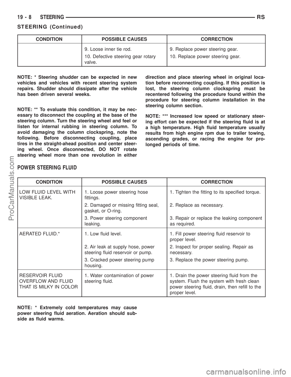
CONDITION POSSIBLE CAUSES CORRECTION
9. Loose inner tie rod. 9. Replace power steering gear.
10. Defective steering gear rotary
valve.10. Replace power steering gear.
NOTE: * Steering shudder can be expected in new
vehicles and vehicles with recent steering system
repairs. Shudder should dissipate after the vehicle
has been driven several weeks.
NOTE: ** To evaluate this condition, it may be nec-
essary to disconnect the coupling at the base of the
steering column. Turn the steering wheel and feel or
listen for internal rubbing in steering column. To
avoid damaging the column clockspring, note the
following. Before disconnecting coupling, place
tires in the straight-ahead position and center steer-
ing wheel. Once disconnected, DO NOT rotate
steering wheel more than one revolution in eitherdirection and place steering wheel in original loca-
tion before reconnecting coupling. If this position is
lost, the steering column clockspring must be
recentered following the procedure found within the
procedure for steering column installation in the
steering column section.
NOTE: *** Increased low speed or stationary steer-
ing effort can be expected if the steering fluid is at
a high temperature. High fluid temperature usually
results from high engine rpm due to trailer towing,
ascending grades, or racing the engine for pro-
longed periods of time.
POWER STEERING FLUID
CONDITION POSSIBLE CAUSES CORRECTION
LOW FLUID LEVEL WITH
VISIBLE LEAK.1. Loose power steering hose
fittings.1. Tighten the fitting to its specified torque.
2. Damaged or missing fitting seal,
gasket, or O-ring.2. Replace as necessary.
3. Power steering component
leaking.3. Repair or replace the leaking component
as required.
AERATED FLUID.* 1. Low fluid level. 1. Fill power steering fluid reservoir to
proper level.
2. Air leak at supply hose, power
steering fluid reservoir or pump.2. Inspect for proper sealing. Repair as
necessary.
3. Cracked power steering pump
housing.3. Replace the power steering pump.
RESERVOIR FLUID
OVERFLOW AND FLUID
THAT IS MILKY IN COLOR1. Water contamination of power
steering fluid.1. Drain the power steering fluid from the
system. Flush the system with fresh clean
power steering fluid, drain, then refill to the
proper level.
NOTE: * Extremely cold temperatures may cause
power steering fluid aeration. Aeration should sub-
side as fluid warms.
19 - 8 STEERINGRS
STEERING (Continued)
ProCarManuals.com
Page 1513 of 2399
COLUMN
TABLE OF CONTENTS
page page
COLUMN
DESCRIPTION - STEERING COLUMN.......10
WARNING
WARNINGS AND CAUTIONS.............10
DIAGNOSIS AND TESTING - STEERING
COLUMN............................12
REMOVAL.............................12
INSTALLATION.........................13
SPECIFICATIONS
COLUMN TORQUE....................14
IGNITION SWITCH
REMOVAL.............................15
INSTALLATION.........................16
LOCK CYLINDER HOUSING
DESCRIPTION - IGNITION INTERLOCK......17
REMOVAL.............................17INSTALLATION.........................20
KEY/LOCK CYLINDER
DESCRIPTION.........................21
OPERATION...........................21
REMOVAL.............................22
INSTALLATION.........................22
GEAR SHIFT LEVER
REMOVAL.............................22
INSTALLATION.........................22
SHROUD
REMOVAL.............................23
INSTALLATION.........................23
STEERING WHEEL
REMOVAL.............................23
INSTALLATION.........................25
COLUMN
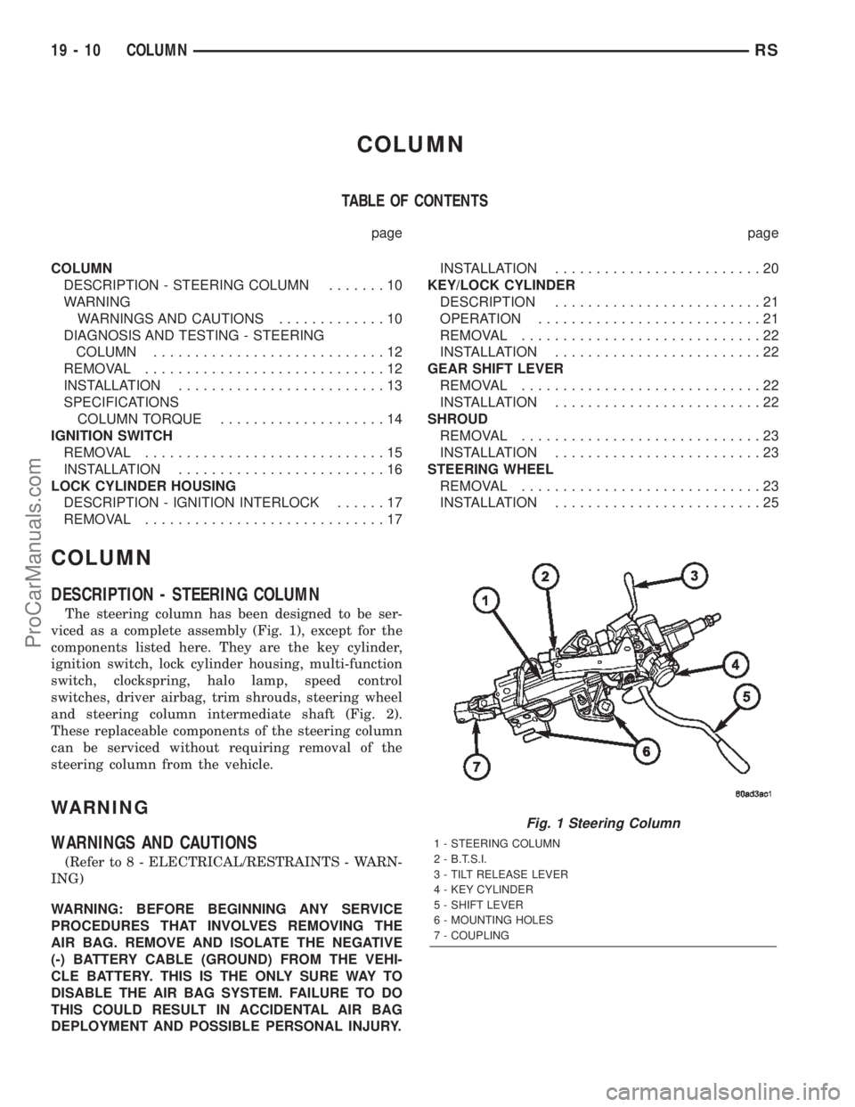
DESCRIPTION - STEERING COLUMN
The steering column has been designed to be ser-
viced as a complete assembly (Fig. 1), except for the
components listed here. They are the key cylinder,
ignition switch, lock cylinder housing, multi-function
switch, clockspring, halo lamp, speed control
switches, driver airbag, trim shrouds, steering wheel
and steering column intermediate shaft (Fig. 2).
These replaceable components of the steering column
can be serviced without requiring removal of the
steering column from the vehicle.
WARNING
WARNINGS AND CAUTIONS
(Refer to 8 - ELECTRICAL/RESTRAINTS - WARN-
ING)
WARNING: BEFORE BEGINNING ANY SERVICE
PROCEDURES THAT INVOLVES REMOVING THE
AIR BAG. REMOVE AND ISOLATE THE NEGATIVE
(-) BATTERY CABLE (GROUND) FROM THE VEHI-
CLE BATTERY. THIS IS THE ONLY SURE WAY TO
DISABLE THE AIR BAG SYSTEM. FAILURE TO DO
THIS COULD RESULT IN ACCIDENTAL AIR BAG
DEPLOYMENT AND POSSIBLE PERSONAL INJURY.
Fig. 1 Steering Column
1 - STEERING COLUMN
2 - B.T.S.I.
3 - TILT RELEASE LEVER
4 - KEY CYLINDER
5 - SHIFT LEVER
6 - MOUNTING HOLES
7 - COUPLING
19 - 10 COLUMNRS
ProCarManuals.com
Page 1515 of 2399
WARNING: THE AIR BAG SYSTEM IS A SENSITIVE,
COMPLEX ELECTRO-MECHANICAL UNIT. BEFORE
ATTEMPTING TO DIAGNOSE, REMOVE OR INSTALL
THE AIR BAG SYSTEM COMPONENTS YOU MUST
FIRST DISCONNECT AND ISOLATE THE BATTERY
NEGATIVE (GROUND) CABLE. THEN WAIT TWO
MINUTES FOR THE SYSTEM CAPACITOR TO DIS-
CHARGE. FAILURE TO DO SO COULD RESULT IN
ACCIDENTAL DEPLOYMENT OF THE AIR BAG AND
POSSIBLE PERSONAL INJURY. THE FASTENERS,
SCREWS, AND BOLTS, ORIGINALLY USED FOR
THE AIR BAG COMPONENTS, HAVE SPECIAL
COATINGS AND ARE SPECIFICALLY DESIGNED
FOR THE AIR BAG SYSTEM. THEY MUST NEVER
BE REPLACED WITH ANY SUBSTITUTES. ANYTIME
A NEW FASTENER IS NEEDED, REPLACE WITH
THE CORRECT FASTENERS PROVIDED IN THE
SERVICE PACKAGE OR FASTENERS LISTED IN
THE PARTS BOOKS.
WARNING: SAFETY GOGGLES SHOULD BE WORN
AT ALL TIMES WHEN WORKING ON STEERING
COLUMNS.
CAUTION: Disconnect negative (ground) cable from
the battery before servicing any column compo-
nent.
CAUTION: Do not attempt to remove the pivot pins
to disassemble the tilting mechanism. Damage will
occur.
DIAGNOSIS AND TESTING - STEERING
COLUMN
For diagnosis of conditions relating to the steering
column (Refer to 19 - STEERING - DIAGNOSIS ANDTESTING) and (Refer to 19 - STEERING - DIAGNO-
SIS AND TESTING).
REMOVAL
NOTE: Before proceeding, (Refer to 19 - STEERING/
COLUMN - WARNING).
(1) Make sure the front wheels of the vehicle are
in the STRAIGHT AHEAD position before beginning
the column removal procedure.
(2) Disconnect negative (ground) cable from the
battery and isolate cable from battery terminal.
(3) Remove the lower shroud (Refer to 19 -
STEERING/COLUMN/LOWER SHROUD - REMOV-
AL).
(4) Remove the traction off switch.
(5) Remove the upper shroud.
(6) Remove the cluster trim bezel (Refer to 23 -
BODY/INSTRUMENT PANEL/CLUSTER BEZEL -
REMOVAL).
(7) Remove the knee blocker (Refer to 23 - BODY/
INSTRUMENT PANEL/STEERING COLUMN
OPENING COVER - REMOVAL).
(8) Remove the parking brake handle link.
(9) Remove the knee blocker reinforcement (Refer
to 23 - BODY/INSTRUMENT PANEL/KNEE
BLOCKER - REMOVAL).
(10) Remove the airbag (Refer to 8 - ELECTRI-
CAL/RESTRAINTS/DRIVER AIRBAG - REMOVAL).
(11) Remove the steering wheel retaining nut.
(12) Remove the vibration damper weight.
(13) Remove the steering wheel (Refer to 19 -
STEERING/COLUMN/STEERING WHEEL -
REMOVAL). (Fig. 3)
(14) Disconnect the wiring harness connectors
from the clockspring, multi-function switch, halo
lamp, SKIM module, ignition switch and BTSI sole-
noid.
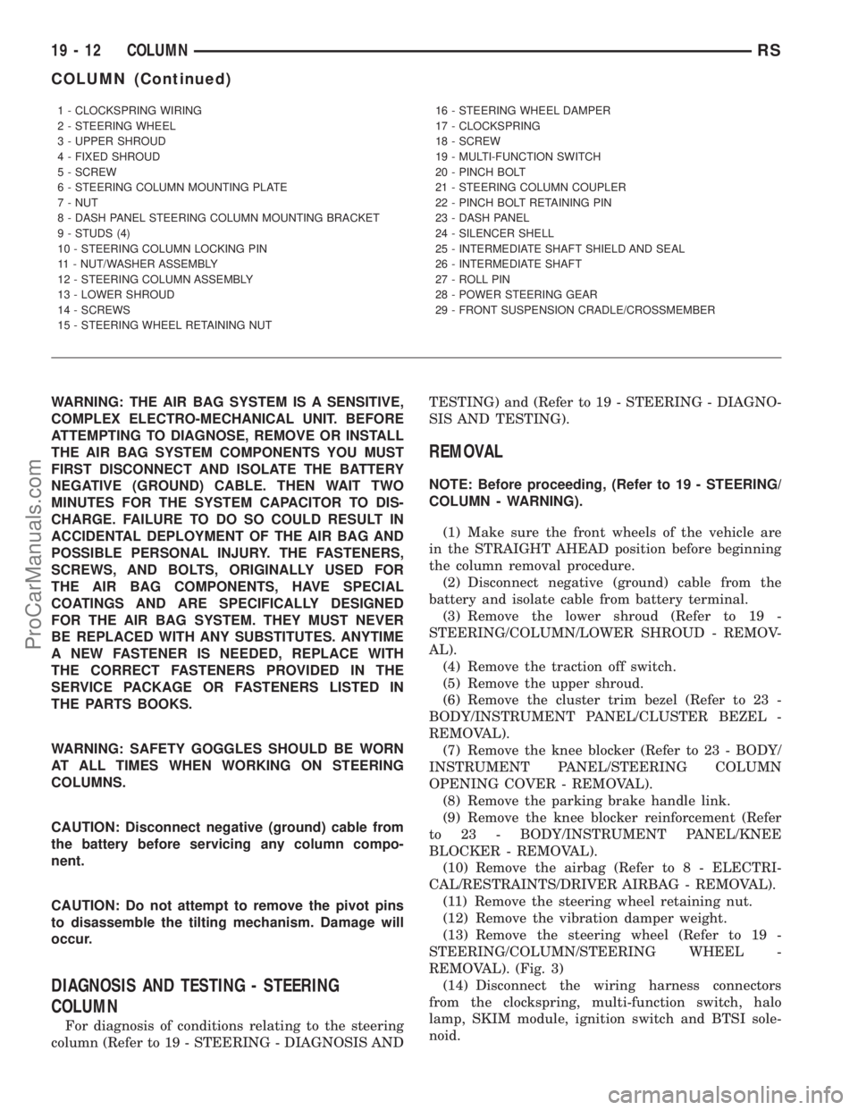
1 - CLOCKSPRING WIRING
2 - STEERING WHEEL
3 - UPPER SHROUD
4 - FIXED SHROUD
5 - SCREW
6 - STEERING COLUMN MOUNTING PLATE
7 - NUT
8 - DASH PANEL STEERING COLUMN MOUNTING BRACKET
9 - STUDS (4)
10 - STEERING COLUMN LOCKING PIN
11 - NUT/WASHER ASSEMBLY
12 - STEERING COLUMN ASSEMBLY
13 - LOWER SHROUD
14 - SCREWS
15 - STEERING WHEEL RETAINING NUT16 - STEERING WHEEL DAMPER
17 - CLOCKSPRING
18 - SCREW
19 - MULTI-FUNCTION SWITCH
20 - PINCH BOLT
21 - STEERING COLUMN COUPLER
22 - PINCH BOLT RETAINING PIN
23 - DASH PANEL
24 - SILENCER SHELL
25 - INTERMEDIATE SHAFT SHIELD AND SEAL
26 - INTERMEDIATE SHAFT
27 - ROLL PIN
28 - POWER STEERING GEAR
29 - FRONT SUSPENSION CRADLE/CROSSMEMBER
19 - 12 COLUMNRS
COLUMN (Continued)
ProCarManuals.com
Page 1516 of 2399
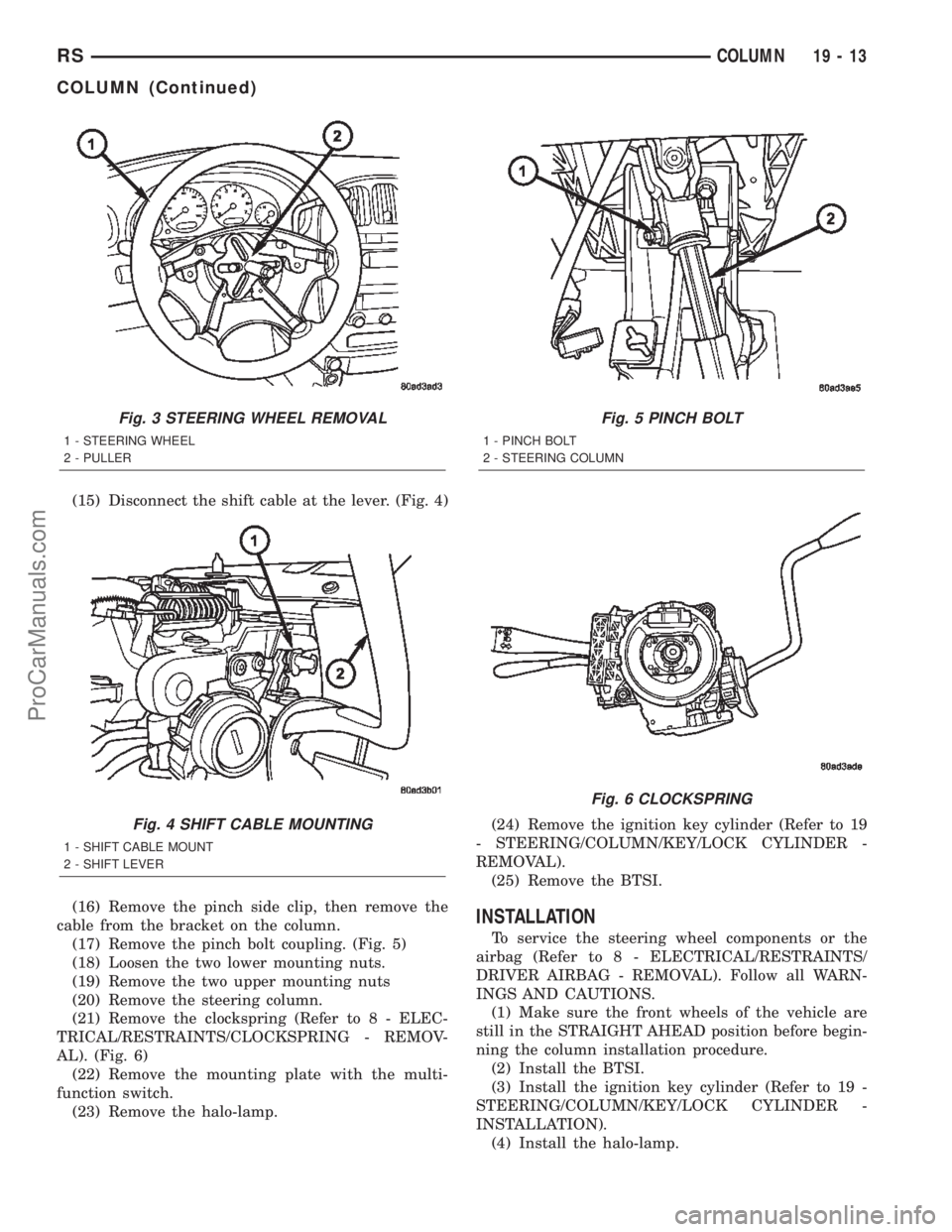
(15) Disconnect the shift cable at the lever. (Fig. 4)
(16) Remove the pinch side clip, then remove the
cable from the bracket on the column.
(17) Remove the pinch bolt coupling. (Fig. 5)
(18) Loosen the two lower mounting nuts.
(19) Remove the two upper mounting nuts
(20) Remove the steering column.
(21) Remove the clockspring (Refer to 8 - ELEC-
TRICAL/RESTRAINTS/CLOCKSPRING - REMOV-
AL). (Fig. 6)
(22) Remove the mounting plate with the multi-
function switch.
(23) Remove the halo-lamp.(24) Remove the ignition key cylinder (Refer to 19
- STEERING/COLUMN/KEY/LOCK CYLINDER -
REMOVAL).
(25) Remove the BTSI.
INSTALLATION
To service the steering wheel components or the
airbag (Refer to 8 - ELECTRICAL/RESTRAINTS/
DRIVER AIRBAG - REMOVAL). Follow all WARN-
INGS AND CAUTIONS.
(1) Make sure the front wheels of the vehicle are
still in the STRAIGHT AHEAD position before begin-
ning the column installation procedure.
(2) Install the BTSI.
(3) Install the ignition key cylinder (Refer to 19 -
STEERING/COLUMN/KEY/LOCK CYLINDER -
INSTALLATION).
(4) Install the halo-lamp.
Fig. 3 STEERING WHEEL REMOVAL
1 - STEERING WHEEL
2 - PULLER
Fig. 4 SHIFT CABLE MOUNTING
1 - SHIFT CABLE MOUNT
2 - SHIFT LEVER
Fig. 5 PINCH BOLT
1 - PINCH BOLT
2 - STEERING COLUMN
Fig. 6 CLOCKSPRING
RSCOLUMN19-13
COLUMN (Continued)
ProCarManuals.com
Page 1517 of 2399
(5) Install the mounting plate with the multi-func-
tion switch.
(6) Install the clockspring (Refer to 8 - ELECTRI-
CAL/RESTRAINTS/CLOCKSPRING - INSTALLA-
TION).
(7) Install the steering column to the vehicle.
(8) Install the two upper mounting nuts
(9) Tighten the two lower mounting nuts and the
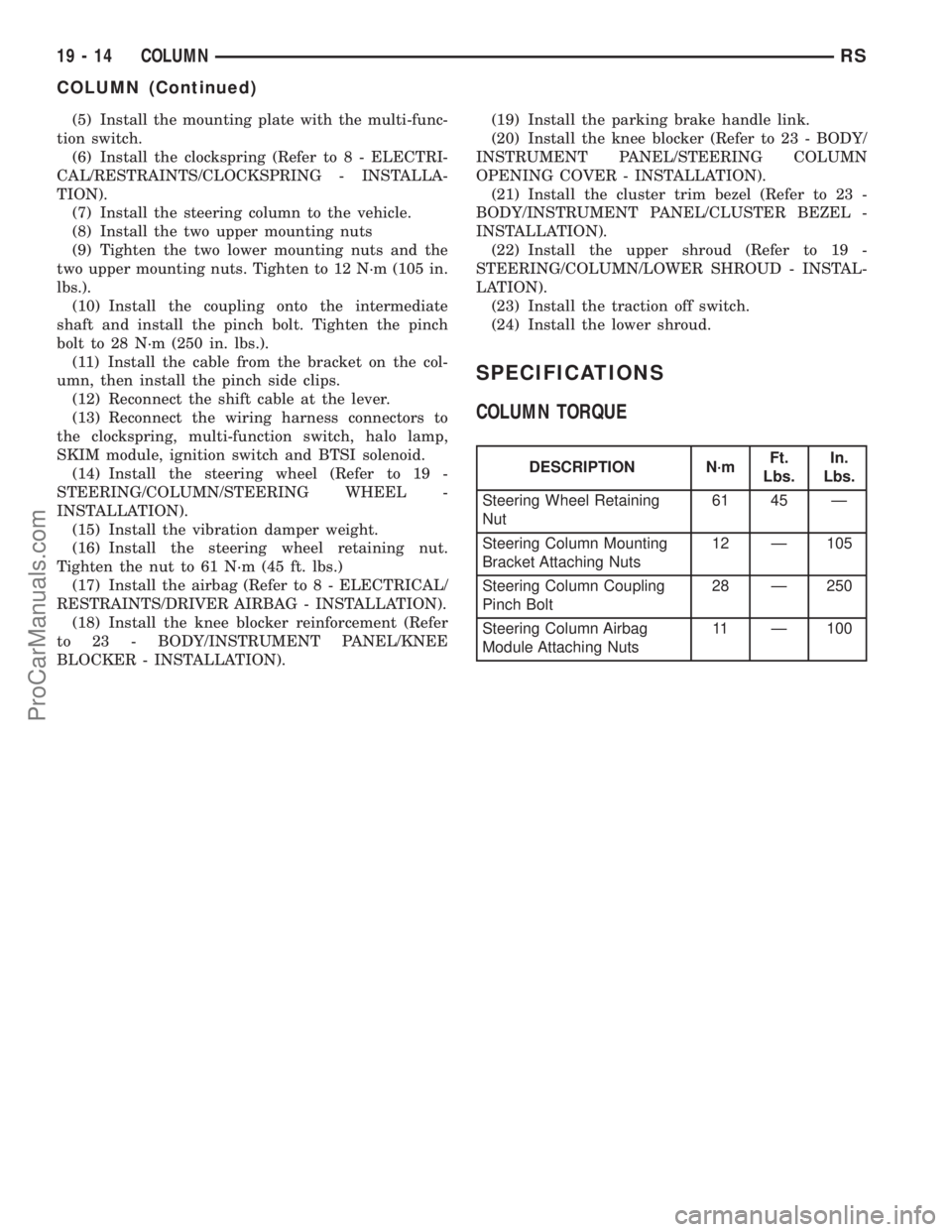
two upper mounting nuts. Tighten to 12 N´m (105 in.
lbs.).
(10) Install the coupling onto the intermediate
shaft and install the pinch bolt. Tighten the pinch
bolt to 28 N´m (250 in. lbs.).
(11) Install the cable from the bracket on the col-
umn, then install the pinch side clips.
(12) Reconnect the shift cable at the lever.
(13) Reconnect the wiring harness connectors to
the clockspring, multi-function switch, halo lamp,
SKIM module, ignition switch and BTSI solenoid.
(14) Install the steering wheel (Refer to 19 -
STEERING/COLUMN/STEERING WHEEL -
INSTALLATION).
(15) Install the vibration damper weight.
(16) Install the steering wheel retaining nut.
Tighten the nut to 61 N´m (45 ft. lbs.)
(17) Install the airbag (Refer to 8 - ELECTRICAL/
RESTRAINTS/DRIVER AIRBAG - INSTALLATION).
(18) Install the knee blocker reinforcement (Refer
to 23 - BODY/INSTRUMENT PANEL/KNEE
BLOCKER - INSTALLATION).(19) Install the parking brake handle link.
(20) Install the knee blocker (Refer to 23 - BODY/
INSTRUMENT PANEL/STEERING COLUMN
OPENING COVER - INSTALLATION).
(21) Install the cluster trim bezel (Refer to 23 -
BODY/INSTRUMENT PANEL/CLUSTER BEZEL -
INSTALLATION).
(22) Install the upper shroud (Refer to 19 -
STEERING/COLUMN/LOWER SHROUD - INSTAL-
LATION).
(23) Install the traction off switch.
(24) Install the lower shroud.
SPECIFICATIONS
COLUMN TORQUE
DESCRIPTION N´mFt.
Lbs.In.
Lbs.
Steering Wheel Retaining
Nut61 45 Ð
Steering Column Mounting
Bracket Attaching Nuts12 Ð 105
Steering Column Coupling
Pinch Bolt28 Ð 250
Steering Column Airbag
Module Attaching Nuts11 Ð 100
19 - 14 COLUMNRS
COLUMN (Continued)
ProCarManuals.com