bcm CHRYSLER VOYAGER 2002 Service Manual
[x] Cancel search | Manufacturer: CHRYSLER, Model Year: 2002, Model line: VOYAGER, Model: CHRYSLER VOYAGER 2002Pages: 2399, PDF Size: 57.96 MB
Page 330 of 2399
REMOTE SWITCHES
DESCRIPTION
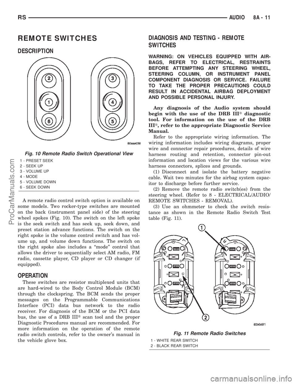
A remote radio control switch option is available on
some models. Two rocker-type switches are mounted
on the back (instrument panel side) of the steering
wheel spokes (Fig. 10). The switch on the left spoke
is the seek switch and has seek up, seek down, and
preset station advance functions. The switch on the
right spoke is the volume control switch and has vol-
ume up, and volume down functions. The switch on
the right spoke also includes a ªmodeº control that
allows the driver to sequentially select AM radio, FM
radio, cassette player, CD player or CD changer (if
equipped).
OPERATION
These switches are resistor multiplexed units that
are hard-wired to the Body Control Module (BCM)
through the clockspring. The BCM sends the proper
messages on the Programmable Communications
Interface (PCI) data bus network to the radio
receiver. For diagnosis of the BCM or the PCI data
bus, the use of a DRB IIItscan tool and the proper
Diagnostic Procedures manual are recommended. For
more information on the operation of the remote
radio switch controls, refer to the owner's manual in
the vehicle glove box.
DIAGNOSIS AND TESTING - REMOTE
SWITCHES
WARNING: ON VEHICLES EQUIPPED WITH AIR-
BAGS, REFER TO ELECTRICAL, RESTRAINTS
BEFORE ATTEMPTING ANY STEERING WHEEL,
STEERING COLUMN, OR INSTRUMENT PANEL
COMPONENT DIAGNOSIS OR SERVICE. FAILURE
TO TAKE THE PROPER PRECAUTIONS COULD
RESULT IN ACCIDENTAL AIRBAG DEPLOYMENT
AND POSSIBLE PERSONAL INJURY.
Any diagnosis of the Audio system should
begin with the use of the DRB IIItdiagnostic
tool. For information on the use of the DRB
IIIt, refer to the appropriate Diagnostic Service
Manual.
Refer to the appropriate wiring information. The
wiring information includes wiring diagrams, proper
wire and connector repair procedures, details of wire
harness routing and retention, connector pin-out
information and location views for the various wire
harness connectors, splices and grounds.
(1) Disconnect and isolate the battery negative
cable. Wait two minutes for the airbag system capac-
itor to discharge before further service.
(2) Remove the remote radio switch(es) from the
steering wheel. (Refer to 8 - ELECTRICAL/AUDIO/
REMOTE SWITCHES - REMOVAL).
(3) Use an ohmmeter to check the switch resis-
tance as shown in the Remote Radio Switch Test
table (Fig. 11).
Fig. 10 Remote Radio Switch Operational View
1 - PRESET SEEK
2 - SEEK UP
3 - VOLUME UP
4 - MODE
5 - VOLUME DOWN
6 - SEEK DOWN
Fig. 11 Remote Radio Switches
1 - WHITE REAR SWITCH
2 - BLACK REAR SWITCH
RSAUDIO8A-11
ProCarManuals.com
Page 331 of 2399

REMOTE RADIO SWITCH TEST
SWITCH POSITION RESISTANCE
VOLUME UP 7320 OHMS
VOLUME DOWN 1210 OHMS
SEEK UP 4530 OHMS
SEEK DOWN 2050 OHMS
PRE-SET STATION ADVANCE 10 OHMS
NOTE: The right remote radio switch back is white
in color. The left switch back is black in color. The
right/left remote radio switch orientation is with the
steering wheel installed, and driver in drivers seat.
(4) If the switch resistance checks OK, go to Step
5. If not OK, replace the faulty switch.
(5) Check for continuity between the ground cir-
cuit cavity of the switch wire harness connector and
a good ground. There should be continuity. If OK, go
to Step 6. If not OK, repair the open circuit as
required.
(6) Unplug the 24-way white wire harness connec-
tor from the Body Control Module (BCM). Check for
continuity between the radio control circuit cavity of
the remote radio switch wire harness connector and a
good ground. There should be no continuity. If OK, go
to Step 7. If not OK, repair the short circuit as
required.
(7) Check for continuity between the radio control
circuit cavities of the remote radio switch wire har-
ness connector and the BCM wire harness connector.
There should be continuity. If OK, refer to the proper
Diagnostic Procedures manual to test the BCM and
the PCI data bus. If not OK, repair the open circuit
as required.
REMOVAL
WARNING: ON VEHICLES EQUIPPED WITH AIR-
BAGS, REFER TO ELECTRICAL, RESTRAINTS
BEFORE ATTEMPTING ANY STEERING WHEEL,
STEERING COLUMN, OR INSTRUMENT PANEL
COMPONENT DIAGNOSIS OR SERVICE. FAILURE
TO TAKE THE PROPER PRECAUTIONS COULD
RESULT IN ACCIDENTAL AIRBAG DEPLOYMENT
AND POSSIBLE PERSONAL INJURY.
(1) Disconnect and isolate the battery negative
cable. Wait two minutes for the airbag system capac-
itor to discharge before further service.
(2) Remove the driver side airbag module from the
vehicle. Refer to ELECTRICAL/RESTRAINTS/
DRIVER AIR BAG.(3) Remove the steering wheel from the steering
column. Refer to STEERING/COLUMN/STEERING
WHEEL.
(4) Unplug the wire harness connector from the
remote radio switch (s).
(5) Remove three screws securing steering wheel
rear cover.
(6) Remove the remote radio switch from the steer-
ing wheel by depressing tabs on each side of each
switch.
NOTE: The right remote radio switch back is white
in color. The left switch back is black in color. The
right/left remote radio switch orientation is with the
steering wheel installed, and driver in drivers seat.
INSTALLATION
WARNING: ON VEHICLES EQUIPPED WITH AIR-
BAGS, REFER TO ELECTRICAL, RESTRAINTS
BEFORE ATTEMPTING ANY STEERING WHEEL,
STEERING COLUMN, OR INSTRUMENT PANEL
COMPONENT DIAGNOSIS OR SERVICE. FAILURE
TO TAKE THE PROPER PRECAUTIONS COULD
RESULT IN ACCIDENTAL AIRBAG DEPLOYMENT
AND POSSIBLE PERSONAL INJURY.
(1)
Install remote radio switch to the steering wheel.
(2) Install three screws securing steering wheel
rear cover.
(3) Connect the wire harness to the remote radio
switch.
(4) Install the steering wheel. Refer to STEERING/
COLUMN/STEERING WHEEL.
(5) Install the driver side airbag module. Refer to
ELECTRICAL/RESTRAINTS/DRIVER AIRBAG.
(6) Connect the battery negative cable.
SPEAKER
DIAGNOSIS AND TESTING - SPEAKER
WARNING: DISABLE THE AIRBAG SYSTEM BEFORE
ATTEMPTING ANY STEERING WHEEL, STEERING
COLUMN, SEAT BELT TENSIONER, SIDE AIRBAG,
OR INSTRUMENT PANEL COMPONENT DIAGNOSIS
OR SERVICE. DISCONNECT AND ISOLATE THE BAT-
TERY NEGATIVE (GROUND) CABLE, THEN WAIT
TWO MINUTES FOR THE AIRBAG SYSTEM CAPACI-
TOR TO DISCHARGE BEFORE PERFORMING FUR-
THER DIAGNOSIS OR SERVICE. THIS IS THE ONLY
SURE WAY TO DISABLE THE AIRBAG SYSTEM.
FAILURE TO TAKE THE PROPER PRECAUTIONS
COULD RESULT IN ACCIDENTAL AIRBAG DEPLOY-
MENT AND POSSIBLE PERSONAL INJURY.
8A - 12 AUDIORS
REMOTE SWITCHES (Continued)
ProCarManuals.com
Page 334 of 2399
CHIME/BUZZER
TABLE OF CONTENTS
page page
CHIME/BUZZER
DESCRIPTION..........................1
OPERATION............................1
WARNING.............................1
DIAGNOSIS AND TESTING
DIAGNOSIS AND TESTING - CHIME
SYSTEM.............................1
DIAGNOSIS AND TESTING - DOME LAMP
ON CHIME............................2
DIAGNOSIS AND TESTING - ENGINE
TEMPERATURE CRITICAL CHIME..........2
DIAGNOSIS AND TESTING - EXTERIOR
LAMPS ON CHIME.....................2
DIAGNOSIS AND TESTING - KEY-IN
IGNITION CHIME.......................2DIAGNOSIS AND TESTING - LOW OIL
PRESSURE CHIME.....................3
DIAGNOSIS AND TESTING - SEAT BELT
CHIME...............................3
DIAGNOSIS AND TESTING - SEAT BELT
LAMP...............................3
DIAGNOSIS AND TESTING - TIRE
PRESSURE MONITOR..................3
DIAGNOSIS AND TESTING - TURN SIGNAL
ON CHIME............................3
DIAGNOSIS AND TESTING - WARNING
LAMP ANNOUNCEMENT CHIME...........4
CHIME/BUZZER
DESCRIPTION
The chime/buzzer system provides the driver with
warning chimes for:
²Seat Belt
²Exterior Lamps ON
²Key-In Ignition
²Engine Temperature Critical
²Turn Signals ON
²Dome Lamp ON
²Low Oil Pressure
²High Speed Warning
²Warning Lamp Announcement
²Key-In Accessory
²Low/High Tire Pressure
²Service Tire Pressure Monitor (TPM)
HIGH SPEED WARNING - EXPORT
The chime will sound, acting as a warning to the
driver that the vehicle speed has exceeded 120 3
kph (75 2 mph).
OPERATION
The Chime/Buzzer Warning System is diagnosed
using a DRB llltscan tool. Refer to the proper Body
Diagnostic Procedures Manual.
HIGH SPEED WARNING - EXPORT
When the vehicle speed sensor sees 120 3kph
(75 2 mph), it sends a PCI data bus message to the
Body Control Module (BCM). The BCM then turns onthe chime to let the driver know that the vehicle has
reached a speed greater than 120 3kph(75 2
mph). This audible message will continue until the
vehicle is slowed below the predetermined speed.
WARNING
WARNING: ON VEHICLES EQUIPPED WITH AIR-
BAGS, DISABLE THE AIRBAG SYSTEM BEFORE
ATTEMPTING ANY STEERING WHEEL, STEERING
COLUMN, OR INSTRUMENT PANEL COMPONENT
DIAGNOSIS OR SERVICE. DISCONNECT AND ISO-
LATE THE BATTERY NEGATIVE (GROUND) CABLE,
THEN WAIT TWO MINUTES FOR THE AIRBAG SYS-
TEM CAPACITOR TO DISCHARGE BEFORE PER-
FORMING FURTHER DIAGNOSIS OR SERVICE. THIS
IS THE ONLY SURE WAY TO DISABLE THE AIRBAG
SYSTEM. FAILURE TO TAKE THE PROPER PRE-
CAUTIONS COULD RESULT IN ACCIDENTAL AIR-
BAG DEPLOYMENT AND POSSIBLE PERSONAL
INJURY.
DIAGNOSIS AND TESTING
DIAGNOSIS AND TESTING - CHIME SYSTEM
NO TONE WHEN IGNITION SWITCH IS TURNED ON
AND DRIVER'S SEAT BELT IS NOT BUCKLED.
(1) Using a DRB llltscan tool, actuate chime
(BCM actuates).
(2) Using a voltmeter, check for voltage:
RSCHIME/BUZZER8B-1
ProCarManuals.com
Page 335 of 2399
(a) BCM has two battery feeds at pin 1 and pin
5 of the 6±way connector.
(b) Pin 5 of the (BX2) 32 way connector of the
BCM for ignition feed.
(c) Check voltage (PX2) connector, pin 34 for 12v.
(d) If voltage OK, go to step Step 3
(e) If NO voltage repair as necessary. Refer to
the appropriate wiring information. The wiring
information includes wiring diagrams, proper wire
and connector repair procedures, further details on
wire harness routing and retention, as well as pin-
out and location views for the various wire harness
connectors, splices and grounds.
(3) Check driver's seat belt buckle switch input
(form ORC) for a closed circuit when not buckled. If
input not seen, look for open in wiring or switch. The
switch is grounded when belt is not buckled.
(4) Verify PCI data bus communication between
ORC and BCM.
NO FASTEN SEAT BELT LAMP WHEN IGNITION
SWITCH IS TURNED ON.
(1) Check for burned out lamp.
(2) Using a voltmeter check for voltage at the clus-
ter conncctor:
(a) Pin 2 of the mechanical instrument cluster
for battery feed.
(b) Pin 11 of the mechanical instrument cluster
for ignition voltage.
(3) Repair as necessary.
FASTEN SEAT BELT LAMP OR TONE CONTINUES
FOR MORE THAN 10 SECONDS AFTER SEAT
BELTS ARE FASTENED AND DRIVER'S DOOR IS
CLOSED.
Refer to the proper Body Diagnostic Procedures
manual.
NO TONE WHEN PARK OR HEADLAMPS ARE ON
AND DRIVER'S DOOR IS OPEN.
Make sure ignition is in lock position with the key
removed.
(1) Check the BCM DTC's and BCM sensors to
verify the door is open. Repair as necessary.
(2) Actuate Chime (BCM actuates).
(3) Inspect BCM connectors and wires for proper
connection.
(4) Measure with a voltmeter the voltage (12v) on
BCM connector (PX2) pin 34 with harness connected.
DIAGNOSIS AND TESTING - DOME LAMP ON
CHIME
The dome lamp on chime will warn the driver that
the dome lamps have been left on.When the ignition is OFF and the key is out of the
ignition:
²Driver's door OPEN (door ajar switch is closed to
ground) and
²Dome lamps are ON (dome lamp switch is closed
to ground),
The chime will sound continuously until the driv-
ers door is closed, dome lamps turned OFF or until
the battery protection time out of 15 minutes has
expired. Chime rate: 168 to 192 chimes per minute.
DIAGNOSIS AND TESTING - ENGINE
TEMPERATURE CRITICAL CHIME
The engine temperature critical chime will warn
the driver that the vehicle's engine is overheating.
While monitoring the coolant temperature, the Pow-
ertrain Control Module (PCM) will send on the PCI
data bus as engine temperature every 1.376 seconds
to the cluster. The MIC calculates engine tempera-
ture and determines if a warning should occur. This
feature is functional only with the Ignition Switch in
the Run/Start position.
When the engine temperature reaches 122ÉC
(252ÉF) the MIC requests a chime from the BCM and
the engine temperature lamp comes ON. The MIC
turns OFF the lamp when the engine temperature
reaches 117ÉC (242ÉF). The MIC will chime continu-
ously (request from the BCM). The chime will turn
OFF after four minutes or when the temperature
reaches 117ÉC (242ÉF), which ever occurs first.
DIAGNOSIS AND TESTING - EXTERIOR LAMPS
ON CHIME
The exterior lamp on chime will warn the driver
that the exterior lights have been left on.
With the ignition switch OFF/key out of ignition:
²Driver's door is open (door ajar switch is closed
to ground)
²Parking lamps or headlamps ON (parking lamp
switch is closed to ground)
The chime will sound until lights are turned OFF,
driver's door closed or until the battery protection
time out of 3 minutes has expired.
Chime rate: 168 to 192 chimes per minute.
To test the exterior lamps left on function:
²Turn ignition off
²Remove ignition key
²Turn exterior lamps on with driver's door open.
Chime should sound until lamps are turned off or
driver's door is closed.
DIAGNOSIS AND TESTING - KEY-IN IGNITION
CHIME
The key-in ignition chime will act as a warning to
the driver that the ignition key has been left in the
8B - 2 CHIME/BUZZERRS
CHIME/BUZZER (Continued)
ProCarManuals.com
Page 340 of 2399
(5) Obtain ignition keys to be programmed from
customer (8 keys maximum).
(6) Using the DRB III, erase all ignition keys by
selecting MISCELLANEOUS and ERASE ALL CUR-
RENT IGN. KEYS.
(7) Program all ignition keys.
Learned Key In Ignition - Ignition key transponder
ID is currently programmed in SKIM memory.
ADJUSTABLE PEDAL MODULE
DIAGNOSIS AND TESTING - ADJUSTABLE
PEDAL MODULE
Refer to Appropriate Diagnostic Information.
REMOVAL
(1) Remove adjustable pedal assembly from vehi-
cle. (Refer to 5 - BRAKES/HYDRAULIC/MECHANI-
CAL/PEDAL - REMOVAL)
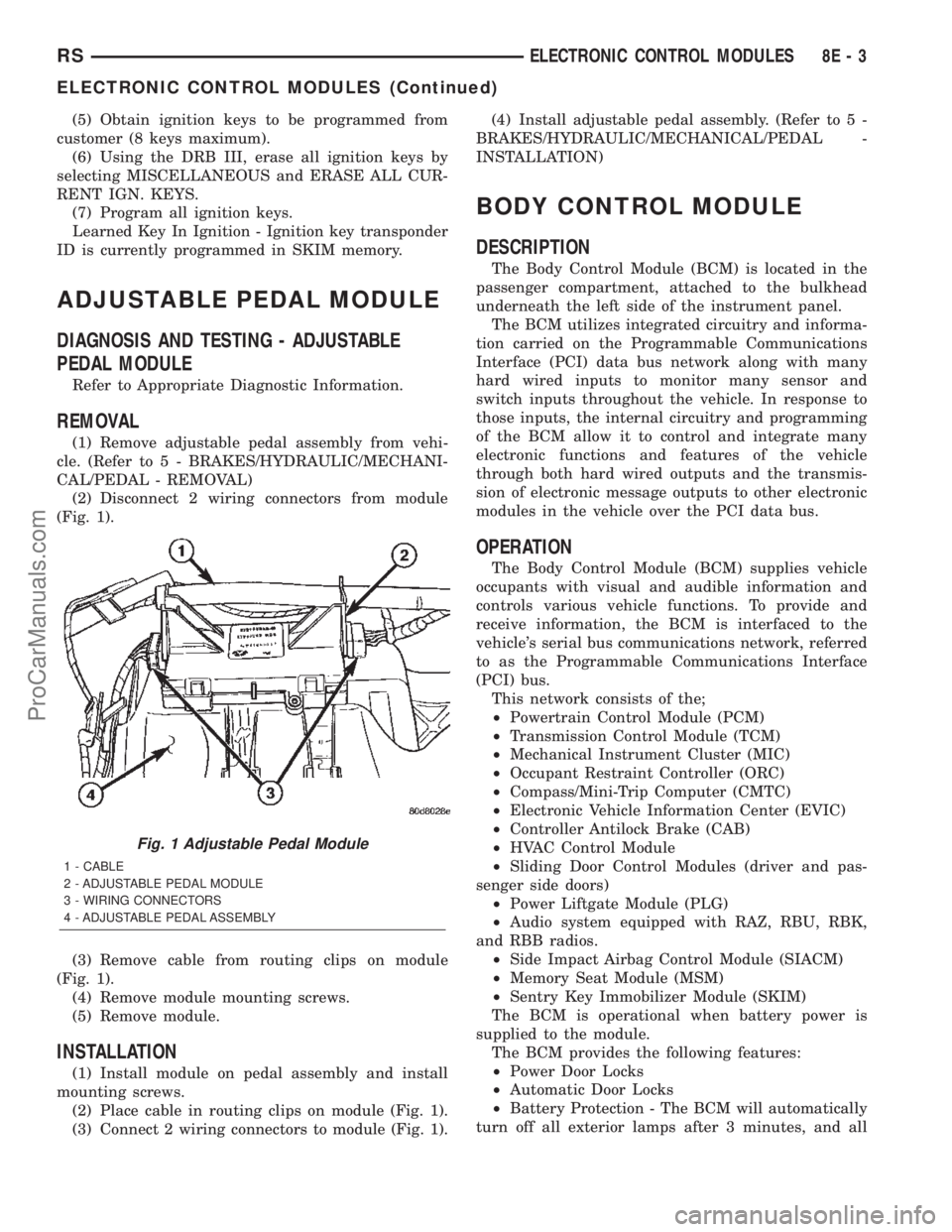
(2) Disconnect 2 wiring connectors from module
(Fig. 1).
(3) Remove cable from routing clips on module
(Fig. 1).
(4) Remove module mounting screws.
(5) Remove module.
INSTALLATION
(1) Install module on pedal assembly and install
mounting screws.
(2) Place cable in routing clips on module (Fig. 1).
(3) Connect 2 wiring connectors to module (Fig. 1).(4) Install adjustable pedal assembly. (Refer to 5 -
BRAKES/HYDRAULIC/MECHANICAL/PEDAL -
INSTALLATION)
BODY CONTROL MODULE
DESCRIPTION
The Body Control Module (BCM) is located in the
passenger compartment, attached to the bulkhead
underneath the left side of the instrument panel.
The BCM utilizes integrated circuitry and informa-
tion carried on the Programmable Communications
Interface (PCI) data bus network along with many
hard wired inputs to monitor many sensor and
switch inputs throughout the vehicle. In response to
those inputs, the internal circuitry and programming
of the BCM allow it to control and integrate many
electronic functions and features of the vehicle
through both hard wired outputs and the transmis-
sion of electronic message outputs to other electronic
modules in the vehicle over the PCI data bus.
OPERATION
The Body Control Module (BCM) supplies vehicle
occupants with visual and audible information and
controls various vehicle functions. To provide and
receive information, the BCM is interfaced to the
vehicle's serial bus communications network, referred
to as the Programmable Communications Interface
(PCI) bus.
This network consists of the;
²Powertrain Control Module (PCM)
²Transmission Control Module (TCM)
²Mechanical Instrument Cluster (MIC)
²Occupant Restraint Controller (ORC)
²Compass/Mini-Trip Computer (CMTC)
²Electronic Vehicle Information Center (EVIC)
²Controller Antilock Brake (CAB)
²HVAC Control Module
²Sliding Door Control Modules (driver and pas-
senger side doors)
²Power Liftgate Module (PLG)
²Audio system equipped with RAZ, RBU, RBK,
and RBB radios.
²Side Impact Airbag Control Module (SIACM)
²Memory Seat Module (MSM)
²Sentry Key Immobilizer Module (SKIM)
The BCM is operational when battery power is
supplied to the module.
The BCM provides the following features:
²Power Door Locks
²Automatic Door Locks
²Battery Protection - The BCM will automatically
turn off all exterior lamps after 3 minutes, and all
Fig. 1 Adjustable Pedal Module
1 - CABLE
2 - ADJUSTABLE PEDAL MODULE
3 - WIRING CONNECTORS
4 - ADJUSTABLE PEDAL ASSEMBLY
RSELECTRONIC CONTROL MODULES8E-3
ELECTRONIC CONTROL MODULES (Continued)
ProCarManuals.com
Page 341 of 2399
interior lamps after 15 minutes after the ignition is
turned off, if they are not turned off by the driver.
²Chime Driver
²Compass/Mini-Trip support.
²Interior Lighting (Courtesy/Reading Lamps)
²BCM Diagnostic Reporting
²Electronic Liftgate Release (with Power Door
Locks)
²Exterior Lighting
²Headlamp Time Delay (with/without Automatic
Headlamps)
²Illuminated Entry
²Fade to Off Interior Lamps - This feature dims
the interior lighting (courtesy lamps) gradually if theBCM does not receive any new inputs that would
cause the interior lamps to remain on.
²Pulse Width Modulated Instrument Panel Dim-
ming
²Door Lock Inhibit - This feature disables the
door lock functions if the key is in the ignition and
either front door is ajar. Pressing the Remote Keyless
Entry (RKE) lock/unlock button under these condi-
tions result in normal lock/unlock activation.
The BCM has the ability to LEARN additional fea-
tures in the vehicle, provided the appropriate switch
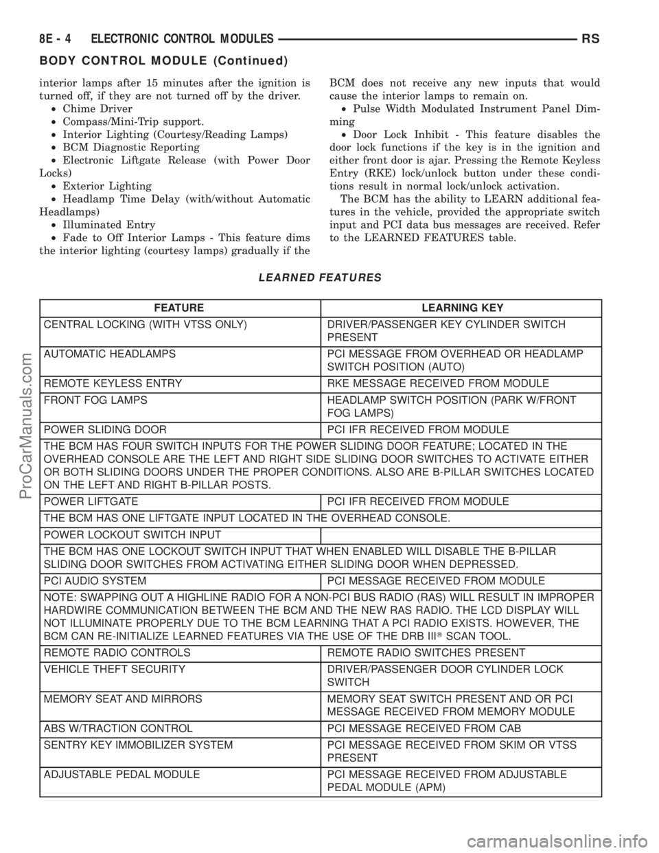
input and PCI data bus messages are received. Refer
to the LEARNED FEATURES table.
LEARNED FEATURES
FEATURE LEARNING KEY
CENTRAL LOCKING (WITH VTSS ONLY) DRIVER/PASSENGER KEY CYLINDER SWITCH
PRESENT
AUTOMATIC HEADLAMPS PCI MESSAGE FROM OVERHEAD OR HEADLAMP
SWITCH POSITION (AUTO)
REMOTE KEYLESS ENTRY RKE MESSAGE RECEIVED FROM MODULE
FRONT FOG LAMPS HEADLAMP SWITCH POSITION (PARK W/FRONT
FOG LAMPS)
POWER SLIDING DOOR PCI IFR RECEIVED FROM MODULE
THE BCM HAS FOUR SWITCH INPUTS FOR THE POWER SLIDING DOOR FEATURE; LOCATED IN THE
OVERHEAD CONSOLE ARE THE LEFT AND RIGHT SIDE SLIDING DOOR SWITCHES TO ACTIVATE EITHER
OR BOTH SLIDING DOORS UNDER THE PROPER CONDITIONS. ALSO ARE B-PILLAR SWITCHES LOCATED
ON THE LEFT AND RIGHT B-PILLAR POSTS.
POWER LIFTGATE PCI IFR RECEIVED FROM MODULE
THE BCM HAS ONE LIFTGATE INPUT LOCATED IN THE OVERHEAD CONSOLE.
POWER LOCKOUT SWITCH INPUT
THE BCM HAS ONE LOCKOUT SWITCH INPUT THAT WHEN ENABLED WILL DISABLE THE B-PILLAR
SLIDING DOOR SWITCHES FROM ACTIVATING EITHER SLIDING DOOR WHEN DEPRESSED.
PCI AUDIO SYSTEM PCI MESSAGE RECEIVED FROM MODULE
NOTE: SWAPPING OUT A HIGHLINE RADIO FOR A NON-PCI BUS RADIO (RAS) WILL RESULT IN IMPROPER
HARDWIRE COMMUNICATION BETWEEN THE BCM AND THE NEW RAS RADIO. THE LCD DISPLAY WILL
NOT ILLUMINATE PROPERLY DUE TO THE BCM LEARNING THAT A PCI RADIO EXISTS. HOWEVER, THE
BCM CAN RE-INITIALIZE LEARNED FEATURES VIA THE USE OF THE DRB IIITSCAN TOOL.
REMOTE RADIO CONTROLS REMOTE RADIO SWITCHES PRESENT
VEHICLE THEFT SECURITY DRIVER/PASSENGER DOOR CYLINDER LOCK
SWITCH
MEMORY SEAT AND MIRRORS MEMORY SEAT SWITCH PRESENT AND OR PCI
MESSAGE RECEIVED FROM MEMORY MODULE
ABS W/TRACTION CONTROL PCI MESSAGE RECEIVED FROM CAB
SENTRY KEY IMMOBILIZER SYSTEM PCI MESSAGE RECEIVED FROM SKIM OR VTSS
PRESENT
ADJUSTABLE PEDAL MODULE PCI MESSAGE RECEIVED FROM ADJUSTABLE
PEDAL MODULE (APM)
8E - 4 ELECTRONIC CONTROL MODULESRS
BODY CONTROL MODULE (Continued)
ProCarManuals.com
Page 342 of 2399
When replacing a BCM there are three modules
available:
²Base
²Midline
²Highline
The Midline controller is used on vehicles that
have Power Door Locks and the Highline controller is
used for vehicles equipped with a Power Liftgate. If a
vehicle is equipped with the Vehicle Theft Security
System, the Midline/Highline controller becomes a
Premium when the theft feature is enabled.
CAUTION: Do not swap Body Control Modules
between vehicles or body controller's off the shelf.
The BCM has internal diagnostic capability that
assists in diagnosing the system error. When an
OPEN or a SHORT circuit exists, the diagnostic tool
can be used to read the BCM faults. The faults are
very descriptive in identifying the appropriate fea-
ture that has faulted.
The only two faults that the BCM logs that con-
clude the replacement of a BCM are faults;
²# 01 - Internal BCM failure (replace BCM)
²# 1F - J1850 Internal Hardware Failure (replace
BCM)
Otherwise the appropriate diagnostic procedures
for each of the features should be taken when the
BCM logs a fault.
REMOVAL
(1) Disconnect and isolate the battery negative
cable.
(2) Remove the lower instrument panel silencer.
(3) Remove the knee blocker and reinforcement
(Refer to 23 - BODY/INSTRUMENT PANEL/KNEE
BLOCKER REINFORCEMENT - REMOVAL).
(4) Disconnect the five wire connectors from the
bottom of the Body Control Module (BCM).
(5) Move bulkhead wiring aside.
(6) Remove the screws holding the BCM to the
bulkhead.
(7) Remove the BCM from the mounting bracket.
INSTALLATION
(1) Install the BCM to the mounting bracket.
(2) Install the screws holding the BCM to the
bulkhead.
(3) Connect the five wire connectors to the bottom
of the Body Control Module (BCM).
(4) Install the knee blocker and reinforcement
(Refer to 23 - BODY/INSTRUMENT PANEL/KNEE
BLOCKER REINFORCEMENT - INSTALLATION).
(5) Install the lower instrument panel silencer.
(6) Connect the battery negative cable.
(7) Verify proper operation of BCM and its func-
tions.
CONTROLLER ANTILOCK
BRAKE
DESCRIPTION
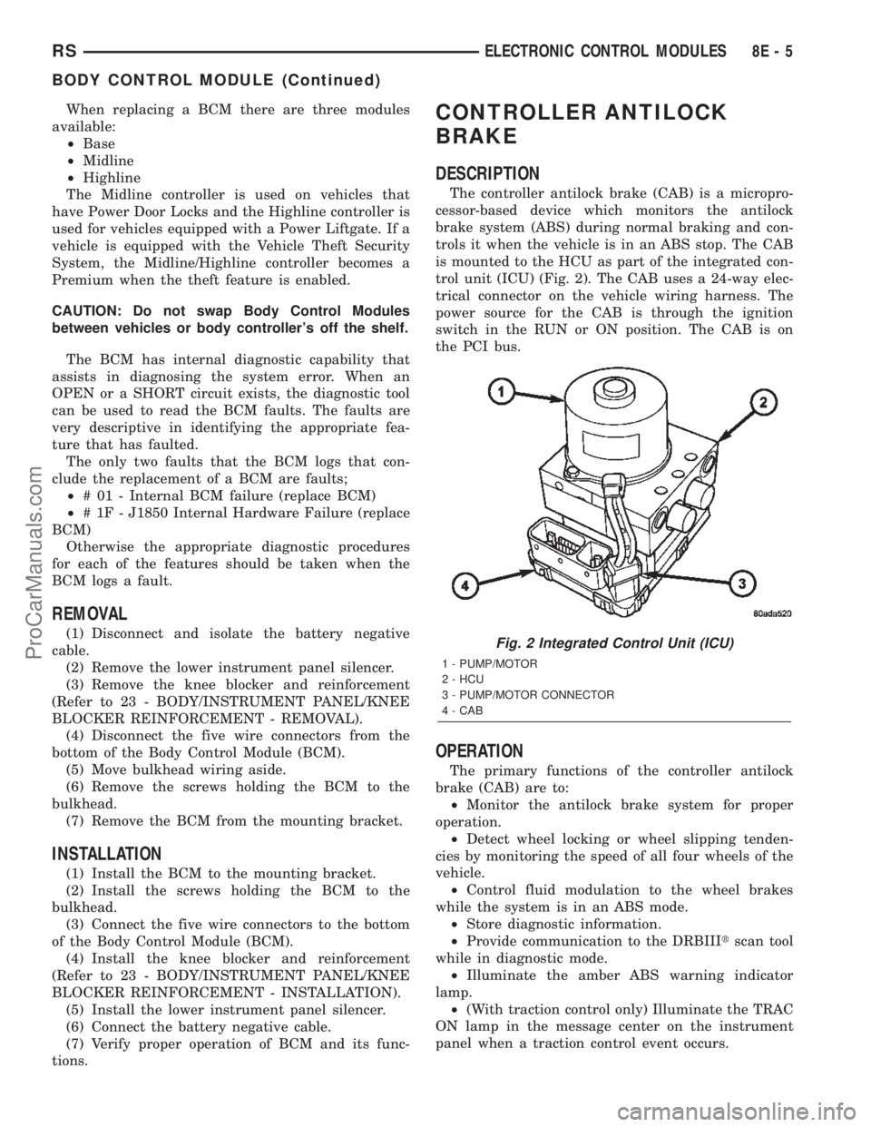
The controller antilock brake (CAB) is a micropro-
cessor-based device which monitors the antilock
brake system (ABS) during normal braking and con-
trols it when the vehicle is in an ABS stop. The CAB
is mounted to the HCU as part of the integrated con-
trol unit (ICU) (Fig. 2). The CAB uses a 24-way elec-
trical connector on the vehicle wiring harness. The
power source for the CAB is through the ignition
switch in the RUN or ON position. The CAB is on
the PCI bus.
OPERATION
The primary functions of the controller antilock
brake (CAB) are to:
²Monitor the antilock brake system for proper
operation.
²Detect wheel locking or wheel slipping tenden-
cies by monitoring the speed of all four wheels of the
vehicle.
²Control fluid modulation to the wheel brakes
while the system is in an ABS mode.
²Store diagnostic information.
²Provide communication to the DRBIIItscan tool
while in diagnostic mode.
²Illuminate the amber ABS warning indicator
lamp.
²(With traction control only) Illuminate the TRAC
ON lamp in the message center on the instrument
panel when a traction control event occurs.
Fig. 2 Integrated Control Unit (ICU)
1 - PUMP/MOTOR
2 - HCU
3 - PUMP/MOTOR CONNECTOR
4 - CAB
RSELECTRONIC CONTROL MODULES8E-5
BODY CONTROL MODULE (Continued)
ProCarManuals.com
Page 364 of 2399

(BCM), and the DRB IIItscan tool. The SKIM trans-
mits and receives RF signals through a tuned
antenna enclosed within a molded plastic ring forma-
tion that is integral to the SKIM housing. When the
SKIM is properly installed on the steering column,
the antenna ring fits snugly around the circumfer-
ence of the ignition lock cylinder housing. If this ring
is not mounted properly, communication problems
may arise in the form of transponder-related faults.
For added system security, each SKIM is pro-
grammed with a unique9Secret Key9code. This code
is stored in memory and is sent over the PCI bus to
the PCM and to each key that is programmed to
work with the vehicle. The9Secret Key9code is there-
fore a common element found in all components of
the Sentry Key Immobilizer System (SKIS). In the
event that a SKIM replacement is required, the
9Secret Key9code can be restored from the PCM by
following the SKIM replacement procedure found in
the DRB IIItscan tool. Proper completion of this
task will allow the existing ignition keys to be repro-
grammed. Therefore, new keys will NOT be needed.
In the event that the original9Secret Key9code can
not be recovered, new ignition keys will be required.
The DRB IIItscan tool will alert the technician if
key replacement is necessary. Another security code,
called a PIN, is used to gain secured access to the
SKIM for service. The SKIM also stores in its mem-
ory the Vehicle Identification Number (VIN), which it
learns through a bus message from the assembly
plant tester. The SKIS scrambles the information
that is communicated between its components in
order to reduce the possibility of unauthorized SKIM
access and/or disabling.
OPERATION
When the ignition switch is moved to the RUN
position, the SKIM transmits an RF signal to the
transponder in the ignition key. The SKIM then
waits for a response RF signal from the transponder
in the key. If the response received identifies the key
as valid, the SKIM sends a9valid key9message to
the PCM over the PCI bus. If the response received
identifies the key as invalid or no response is
received from the transponder in the ignition key, the
SKIM sends an9invalid key9message to the PCM.
The PCM will enable or disable engine operation
based upon the status of the SKIM messages. It is
important to note that the default condition in the
PCM is9invalid key.9Therefore, if no response is
received by the PCM, the engine will be immobilized
after two (2) seconds of running.The SKIM also sends indicator light status mes-
sages to the BCM to operate the light. This is the
method used to turn the light ON solid or to flash it
after the indicator light test is complete to signify a
fault in the SKIS. If the light comes ON and stays
ON solid after the indicator light test, this signifies
that the SKIM has detected a system malfunction
and/or that the SKIS has become inoperative. If the
SKIM detects an invalid keyORa key-related fault
exists, the indicator light will flash following the
indicator light test. The SKIM may also request an
audible chime if the customer key programming fea-
ture is available and the procedure is being utilized
(Refer to 8 - ELECTRICAL/VEHICLE THEFT SECU-
RITY/TRANSPONDER KEY - STANDARD PROCE-
DURE).
REMOVAL
(1)Disconnect and isolate the battery negative cable.
(2) Remove Lower Instrument Panel Cover. Refer
to Body, Instrument Panel, Lower Instrument Panel
Cover, Removal.
(3) Remove the steering column upper and lower
shrouds. Refer to Steering, Column, Column Shroud,
Removal.
(4) Disengage the steering column wire harness
from the Sentry Key Immobilizer Module (SKIM).
(5) Remove the one screws securing the SKIM to
the steering column.
(6) Rotate the SKIM upwards and then to the side
away from the steering column to slide the SKIM
antenna ring from around the ignition switch lock
cylinder housing.
(7) Remove the SKIM from the vehicle.
INSTALLATION
(1) Slip the SKIM antenna ring around the igni-
tion switch lock cylinder housing. Rotate the SKIM
downwards and then towards the steering column.
(2) Install the one screws securing the SKIM to
the steering column.
(3) Engage the steering column wire harness from
the Sentry Key Immobilizer Module (SKIM).
(4) Install the steering column upper and lower
shrouds. Refer to Steering, Column, Column Shroud,
Installation.
(5) Install the Lower Instrument Panel Cover.
Refer to Body, Instrument Panel, Lower Instrument
Panel Cover, Installation.
(6) Connect the battery negative cable.
RSELECTRONIC CONTROL MODULES8E-27
SENTRY KEY IMMOBILIZER MODULE (Continued)
ProCarManuals.com
Page 370 of 2399

MEMORY SEAT/MIRROR
MODULE
DESCRIPTION
Vehicles equipped with the memory seat/mirror
option, utilize a memory module located under the
drivers front seat. This module is basically wired in-
line between the power seat switch and the power
seat track/adjuster motors, or in-line between the
power mirror switch and the power side view mir-
ror(s) motor(s). The MSMM contains a central pro-
cessing unit that communicates with other modules
on the Programmable Communications Interface
(PCI) data bus network.
The Memory Seat/Mirror Module (MSMM) receives
hard wired inputs from the driver power seat switch
and the potentiometers on each of the driver side
power seat track motors, or from the power mirror
switch and the potentiometers on the side view mir-
ror. The MSMM receives messages over the PCI data
bus from the Body Control Module (BCM) (memory
switch status), the Powertrain Control Module (PCM)
(vehicle speed status). The MSMM will prevent the
seat memory recall function from being initiated if
the driver side seat belt is buckled, if the transmis-
sion gear selector lever is not in the Park or Neutral
positions, or if the vehicle is moving.
For diagnosis of the MSMM or the PCI data bus, a
DRB IIItscan tool and the proper Diagnostic Proce-
dures manual are recommended. The MSMM cannot
be repaired and, if faulty or damaged, it must be
replaced. Refer toMemory Systemin the Power
Seat or Power Mirror section of this manual for more
information on the memory system option.
OPERATION
When memory system operation is requested
(depressing of the memory switch), a resistor multi-
plexed signal is sent from the memory switch to the
body control module (BCM). The body control module
will then send the appropriate signals out to the
memory/mirror seat module, the memory/mirror seat
module then applies the voltage supply to the power
seat track or side-view mirror if the proper require-
ments are met. The vehicle speed must equal zero
and the transmission must be in park or neutral in
order for the memory system to function.
DIAGNOSIS AND TESTING - MEMORY
SEAT/MIRROR MODULE
Visually inspect the related wiring harness connec-
tors. Look for broken, bent, pushed out, or corroded
terminals. If any of the above conditions are present,
repair as necessary. If not, use a DRB IIItscan tool
and the proper Diagnostic Procedures Manual to testthe memory/mirror seat module. For complete circuit
diagrams, refer toWiring Diagrams.
REMOVAL
(1) Disconnect and isolate the battery negative
cable.
(2) Remove the driver side front bucket seat
retaining nuts from under the vehicle (Refer to 23 -
BODY/SEATS/SEAT - REMOVAL).
(3) Lift the drivers seat up and out of the mount-
ing holes in the floor pan and lay the seat rearward
to access the module located under the seat. It is not
necessary to disconnect the seat electrical, just use
care not to damage the wiring by over-extending.
(4) Disconnect the memory/mirror seat module
electrical connectors. Depress the retaining tab and
pull straight apart.
(5) Remove the module retaining bolts and remove
the module from the bracket.
INSTALLATION
(1) Position and install the module retaining bolts.
(2) Connect the memory/mirror seat module elec-
trical connectors.
(3) Position the drivers seat in the mounting holes
in the floor pan.
(4) Install the driver side front bucket seat retain-
ing nuts from under the vehicle (Refer to 23 - BODY/
SEATS/SEAT - INSTALLATION).
(5) Connect the battery negative cable.
SLIDING DOOR CONTROL
MODULE
DESCRIPTION
Vehicles equipped with a power sliding door utilize
a sliding door control module. The sliding door con-
trol module is located behind the sliding door trim
panel in the center of the door, just above the sliding
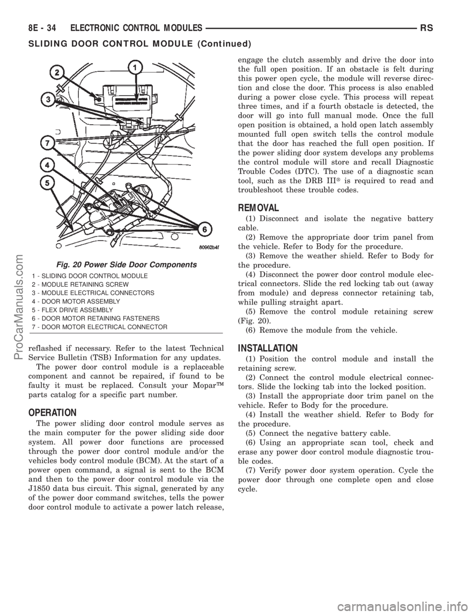
door motor (Fig. 20). This module controls the opera-
tion of the door through the Programmable Commu-
nication Interface (PCI) J1850 data bus circuit and
the Body Control Module. The sliding door control
module contains software technology which enables it
to detect resistance to door travel and to reverse door
travel in order to avoid damage to the door or to
avoid possible personal injury if the obstruction is a
person. This feature functions in both the opening
and closing cycles. If the power sliding door system
develops any problems the control module will store
and recall Diagnostic Trouble Codes (DTC). The use
of a diagnostic scan tool, such as the DRB IIItis
required to read and troubleshoot these trouble
codes. The sliding door control module can be
RSELECTRONIC CONTROL MODULES8E-33
ProCarManuals.com
Page 371 of 2399
reflashed if necessary. Refer to the latest Technical
Service Bulletin (TSB) Information for any updates.
The power door control module is a replaceable
component and cannot be repaired, if found to be
faulty it must be replaced. Consult your MoparŸ
parts catalog for a specific part number.
OPERATION
The power sliding door control module serves as
the main computer for the power sliding side door
system. All power door functions are processed
through the power door control module and/or the
vehicles body control module (BCM). At the start of a
power open command, a signal is sent to the BCM
and then to the power door control module via the
J1850 data bus circuit. This signal, generated by any
of the power door command switches, tells the power
door control module to activate a power latch release,engage the clutch assembly and drive the door into
the full open position. If an obstacle is felt during
this power open cycle, the module will reverse direc-
tion and close the door. This process is also enabled
during a power close cycle. This process will repeat
three times, and if a fourth obstacle is detected, the
door will go into full manual mode. Once the full
open position is obtained, a hold open latch assembly
mounted full open switch tells the control module
that the door has reached the full open position. If
the power sliding door system develops any problems
the control module will store and recall Diagnostic
Trouble Codes (DTC). The use of a diagnostic scan
tool, such as the DRB IIItis required to read and
troubleshoot these trouble codes.
REMOVAL
(1) Disconnect and isolate the negative battery
cable.
(2) Remove the appropriate door trim panel from
the vehicle. Refer to Body for the procedure.
(3) Remove the weather shield. Refer to Body for
the procedure.
(4) Disconnect the power door control module elec-
trical connectors. Slide the red locking tab out (away
from module) and depress connector retaining tab,
while pulling straight apart.
(5) Remove the control module retaining screw
(Fig. 20).
(6) Remove the module from the vehicle.
INSTALLATION
(1) Position the control module and install the
retaining screw.
(2) Connect the control module electrical connec-
tors. Slide the locking tab into the locked position.
(3) Install the appropriate door trim panel on the
vehicle. Refer to Body for the procedure.
(4) Install the weather shield. Refer to Body for
the procedure.
(5) Connect the negative battery cable.
(6) Using an appropriate scan tool, check and
erase any power door control module diagnostic trou-
ble codes.
(7) Verify power door system operation. Cycle the
power door through one complete open and close
cycle.
Fig. 20 Power Side Door Components
1 - SLIDING DOOR CONTROL MODULE
2 - MODULE RETAINING SCREW
3 - MODULE ELECTRICAL CONNECTORS
4 - DOOR MOTOR ASSEMBLY
5 - FLEX DRIVE ASSEMBLY
6 - DOOR MOTOR RETAINING FASTENERS
7 - DOOR MOTOR ELECTRICAL CONNECTOR
8E - 34 ELECTRONIC CONTROL MODULESRS
SLIDING DOOR CONTROL MODULE (Continued)
ProCarManuals.com