clock CHRYSLER VOYAGER 2002 Service Manual
[x] Cancel search | Manufacturer: CHRYSLER, Model Year: 2002, Model line: VOYAGER, Model: CHRYSLER VOYAGER 2002Pages: 2399, PDF Size: 57.96 MB
Page 46 of 2399
(11) Remove the jounce bumper from the dust
shield. The jounce bumper is removed from the dust
shield by collapsing the dust shield until the jounce
bumper can be pulled free from the dust boot.
(12) Remove the spring isolator from the lower
spring seat on the strut (Fig. 38).
(13) Inspect the strut assembly components (Fig.
38) for the following and replace as necessary:
²Inspect the strut for any condition of shaft bind-
ing over the full stroke of the shaft.
²Check the upper mount for cracks and distortion
and its retaining studs for any sign of damage.
²Check the upper seat for stress cracks and wear.
²Check the upper spring isolator for severe dete-
rioration.
²Check for binding of the strut assembly pivot
bearing.
²Inspect the dust shield for rips and deteriora-
tion.
²Inspect the jounce bumper for cracks and signs
of deterioration.
ASSEMBLY - STRUT ASSEMBLY
For the disassembly and assembly of the strut
assembly, use of Strut Spring Compressor, Pentastar
Service Equipment (PSE) tool W-7200, or the equiva-
lent, is recommended to compress the coil spring.
Follow the manufacturer's instructions closely.NOTE: Coil Springs on this vehicle are side-ori-
ented. Springs on the left side of the vehicle have a
left-hand wind top-to-bottom while springs on the
right side have a right-hand wind top-to-bottom.
Left and right springs must not be interchanged.
NOTE: If the coil spring has been removed from the
spring compressor, proceed with the next step, oth-
erwise, proceed with step 5.
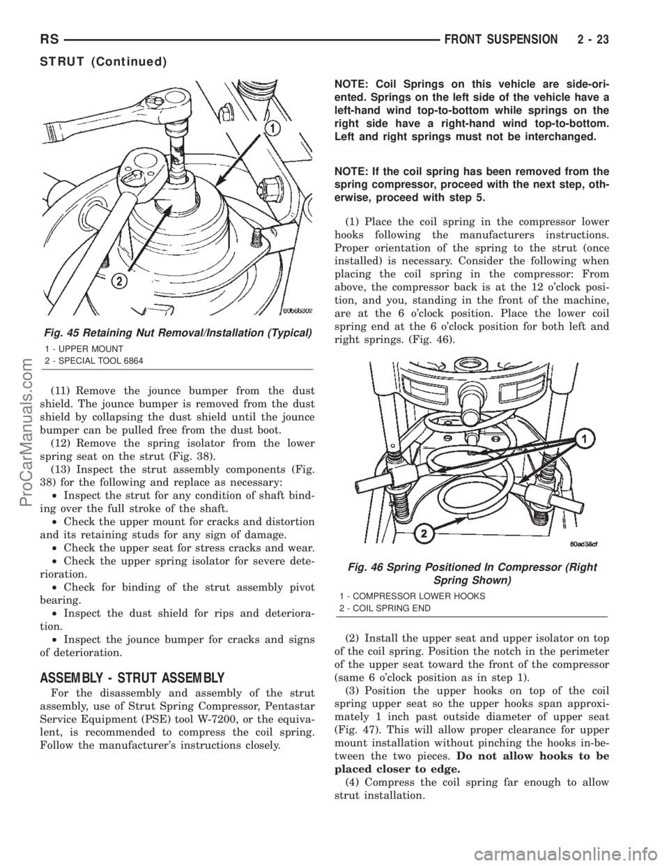
(1) Place the coil spring in the compressor lower
hooks following the manufacturers instructions.
Proper orientation of the spring to the strut (once
installed) is necessary. Consider the following when
placing the coil spring in the compressor: From
above, the compressor back is at the 12 o'clock posi-
tion, and you, standing in the front of the machine,
are at the 6 o'clock position. Place the lower coil
spring end at the 6 o'clock position for both left and
right springs. (Fig. 46).
(2) Install the upper seat and upper isolator on top
of the coil spring. Position the notch in the perimeter
of the upper seat toward the front of the compressor
(same 6 o'clock position as in step 1).
(3) Position the upper hooks on top of the coil
spring upper seat so the upper hooks span approxi-
mately 1 inch past outside diameter of upper seat
(Fig. 47). This will allow proper clearance for upper
mount installation without pinching the hooks in-be-
tween the two pieces.Do not allow hooks to be
placed closer to edge.
(4) Compress the coil spring far enough to allow
strut installation.
Fig. 45 Retaining Nut Removal/Installation (Typical)
1 - UPPER MOUNT
2 - SPECIAL TOOL 6864
Fig. 46 Spring Positioned In Compressor (Right
Spring Shown)
1 - COMPRESSOR LOWER HOOKS
2 - COIL SPRING END
RSFRONT SUSPENSION2-23
STRUT (Continued)
ProCarManuals.com
Page 47 of 2399
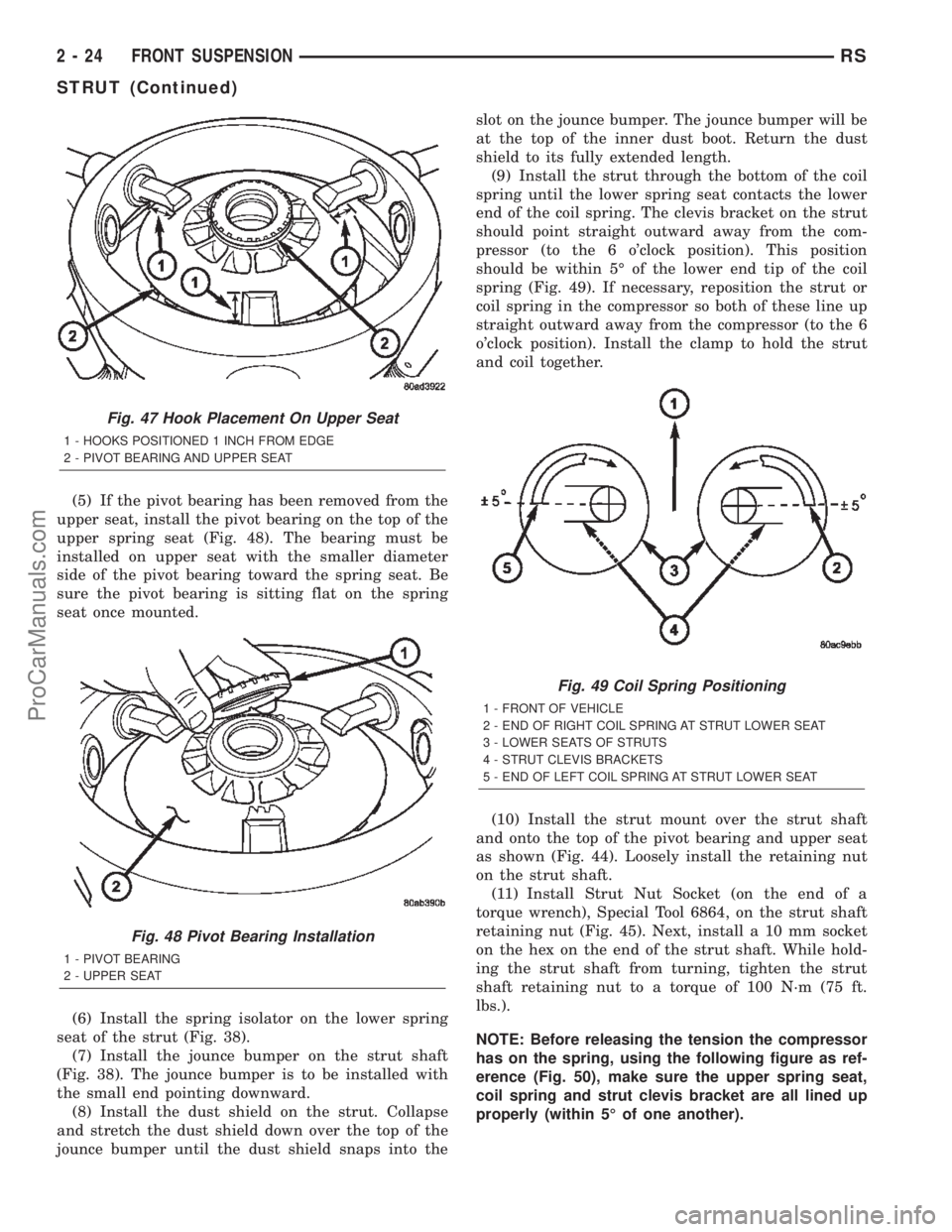
(5) If the pivot bearing has been removed from the
upper seat, install the pivot bearing on the top of the
upper spring seat (Fig. 48). The bearing must be
installed on upper seat with the smaller diameter
side of the pivot bearing toward the spring seat. Be
sure the pivot bearing is sitting flat on the spring
seat once mounted.
(6) Install the spring isolator on the lower spring
seat of the strut (Fig. 38).
(7) Install the jounce bumper on the strut shaft
(Fig. 38). The jounce bumper is to be installed with
the small end pointing downward.
(8) Install the dust shield on the strut. Collapse
and stretch the dust shield down over the top of the
jounce bumper until the dust shield snaps into theslot on the jounce bumper. The jounce bumper will be
at the top of the inner dust boot. Return the dust
shield to its fully extended length.
(9) Install the strut through the bottom of the coil
spring until the lower spring seat contacts the lower
end of the coil spring. The clevis bracket on the strut
should point straight outward away from the com-
pressor (to the 6 o'clock position). This position
should be within 5É of the lower end tip of the coil
spring (Fig. 49). If necessary, reposition the strut or
coil spring in the compressor so both of these line up
straight outward away from the compressor (to the 6
o'clock position). Install the clamp to hold the strut
and coil together.
(10) Install the strut mount over the strut shaft
and onto the top of the pivot bearing and upper seat
as shown (Fig. 44). Loosely install the retaining nut
on the strut shaft.
(11) Install Strut Nut Socket (on the end of a
torque wrench), Special Tool 6864, on the strut shaft
retaining nut (Fig. 45). Next, install a 10 mm socket
on the hex on the end of the strut shaft. While hold-
ing the strut shaft from turning, tighten the strut
shaft retaining nut to a torque of 100 N´m (75 ft.
lbs.).
NOTE: Before releasing the tension the compressor
has on the spring, using the following figure as ref-
erence (Fig. 50), make sure the upper spring seat,
coil spring and strut clevis bracket are all lined up
properly (within 5É of one another).
Fig. 47 Hook Placement On Upper Seat
1 - HOOKS POSITIONED 1 INCH FROM EDGE
2 - PIVOT BEARING AND UPPER SEAT
Fig. 48 Pivot Bearing Installation
1 - PIVOT BEARING
2 - UPPER SEAT
Fig. 49 Coil Spring Positioning
1 - FRONT OF VEHICLE
2 - END OF RIGHT COIL SPRING AT STRUT LOWER SEAT
3 - LOWER SEATS OF STRUTS
4 - STRUT CLEVIS BRACKETS
5 - END OF LEFT COIL SPRING AT STRUT LOWER SEAT
2 - 24 FRONT SUSPENSIONRS
STRUT (Continued)
ProCarManuals.com
Page 59 of 2399
(19) Road test vehicle to ensure proper operation
of the brake system.
JOUNCE BUMPER
DESCRIPTION
There are two jounce bumpers used in the rear
suspension. One mounts to each frame rail above the
rear axle.
OPERATION
The jounce bumper limits suspension travel and
metal-to-metal contact of the rear axle with the
frame under full jounce conditions.
REMOVAL
REMOVAL - AWD AND HEAVY DUTY
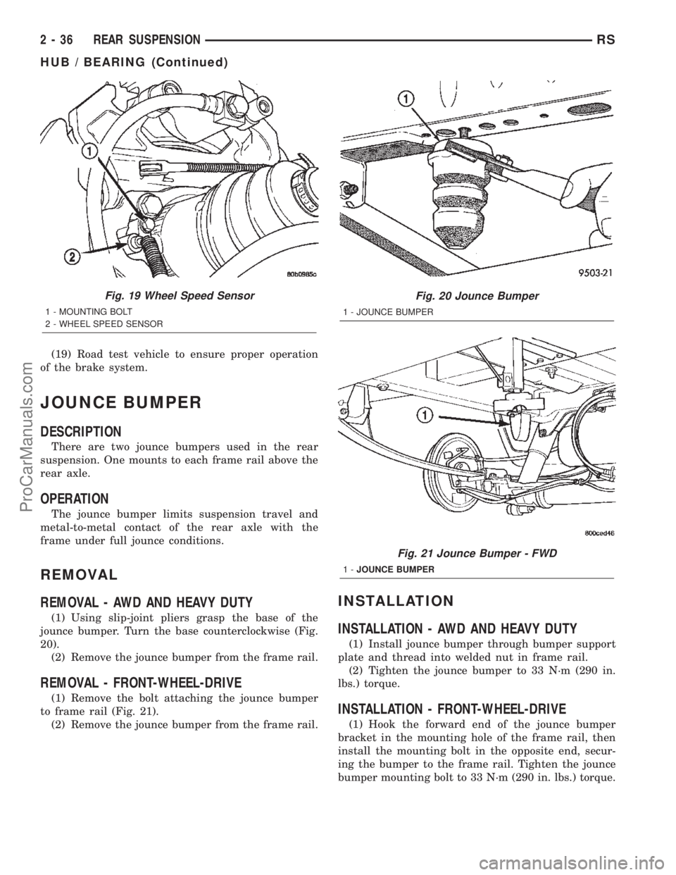
(1) Using slip-joint pliers grasp the base of the
jounce bumper. Turn the base counterclockwise (Fig.
20).
(2) Remove the jounce bumper from the frame rail.
REMOVAL - FRONT-WHEEL-DRIVE
(1) Remove the bolt attaching the jounce bumper
to frame rail (Fig. 21).
(2) Remove the jounce bumper from the frame rail.
INSTALLATION
INSTALLATION - AWD AND HEAVY DUTY
(1) Install jounce bumper through bumper support
plate and thread into welded nut in frame rail.
(2) Tighten the jounce bumper to 33 N´m (290 in.
lbs.) torque.
INSTALLATION - FRONT-WHEEL-DRIVE
(1) Hook the forward end of the jounce bumper
bracket in the mounting hole of the frame rail, then
install the mounting bolt in the opposite end, secur-
ing the bumper to the frame rail. Tighten the jounce
bumper mounting bolt to 33 N´m (290 in. lbs.) torque.
Fig. 19 Wheel Speed Sensor
1 - MOUNTING BOLT
2 - WHEEL SPEED SENSOR
Fig. 20 Jounce Bumper
1 - JOUNCE BUMPER
Fig. 21 Jounce Bumper - FWD
1-JOUNCE BUMPER
2 - 36 REAR SUSPENSIONRS
HUB / BEARING (Continued)
ProCarManuals.com
Page 111 of 2399
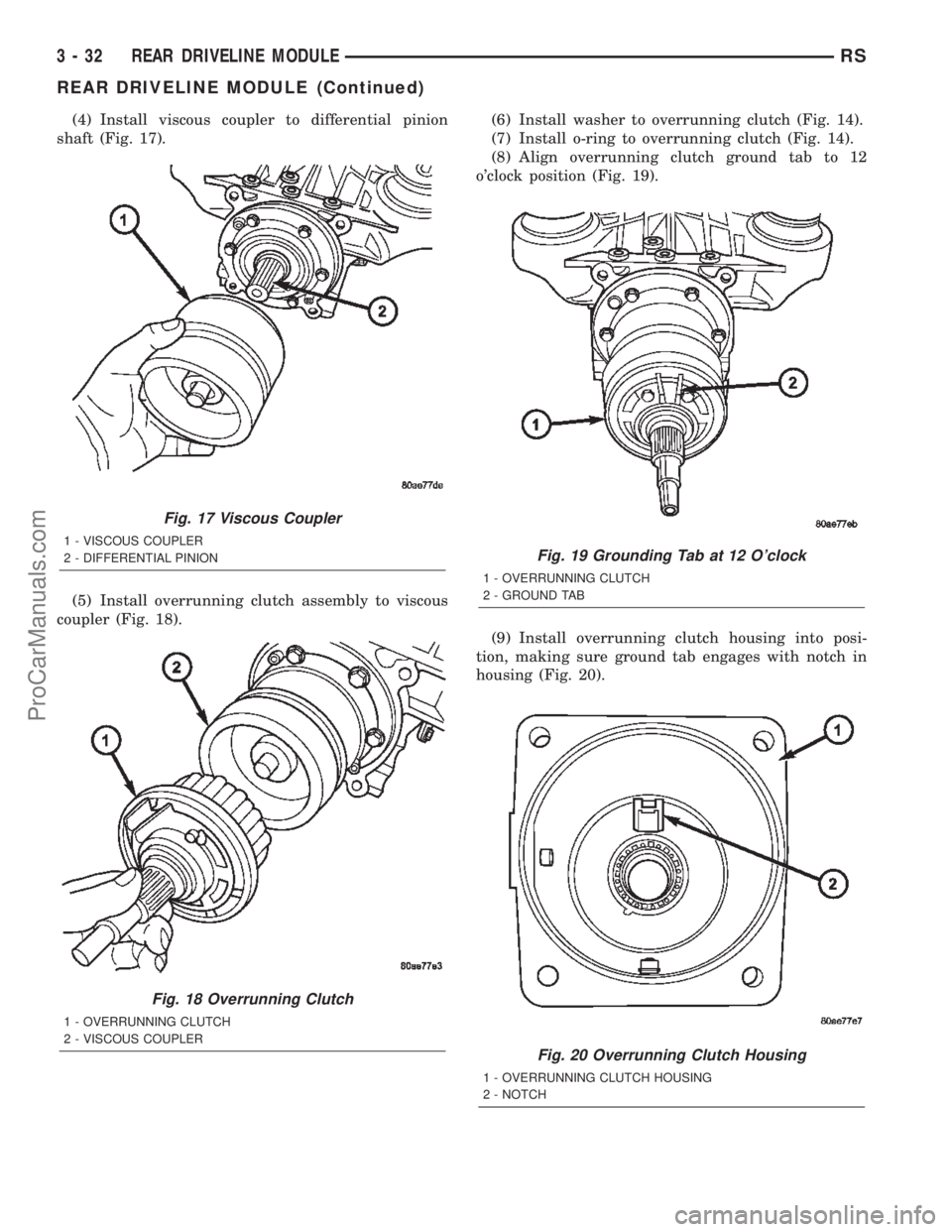
(4) Install viscous coupler to differential pinion
shaft (Fig. 17).
(5) Install overrunning clutch assembly to viscous
coupler (Fig. 18).(6) Install washer to overrunning clutch (Fig. 14).
(7) Install o-ring to overrunning clutch (Fig. 14).
(8) Align overrunning clutch ground tab to 12
o'clock position (Fig. 19).
(9) Install overrunning clutch housing into posi-
tion, making sure ground tab engages with notch in
housing (Fig. 20).
Fig. 17 Viscous Coupler
1 - VISCOUS COUPLER
2 - DIFFERENTIAL PINION
Fig. 18 Overrunning Clutch
1 - OVERRUNNING CLUTCH
2 - VISCOUS COUPLER
Fig. 19 Grounding Tab at 12 O'clock
1 - OVERRUNNING CLUTCH
2 - GROUND TAB
Fig. 20 Overrunning Clutch Housing
1 - OVERRUNNING CLUTCH HOUSING
2 - NOTCH
3 - 32 REAR DRIVELINE MODULERS
REAR DRIVELINE MODULE (Continued)
ProCarManuals.com
Page 115 of 2399
BI-DIRECTIONAL
OVERRUNNING CLUTCH
DESCRIPTION
The bi-directional overrunning clutch (BOC) (Fig.
28) works as a mechanical disconnect between the
front and rear axles, preventing torque from being
transferred from the rear axle to the front. The BOC
is a simply an overrunning clutch which works in
both clockwise and counter-clockwise rotations. This
means that when the output (the rear axle) is rotat-
ing faster in one direction than the input (front axle),
there is no torque transmission. But when the input
speed is equal to the output speed, the unit becomes
locked. The BOC provides significant benefits regard-
ing braking stability, handling, and driveline durabil-
ity. Disconnecting the front and the rear driveline
during braking helps to maintain the braking stabil-
ity of an AWD vehicle. In an ABS/braking event, the
locking of the rear wheels must be avoided for stabil-
ity reasons. Therefore brake systems are designed to
lock the front wheels first. Any torque transfer from
the rear axle to the front axle disturbs the ABS/brak-
ing system and causes potential instabilities on aslippery surface. The BOC de-couples the rear driv-
eline as soon the rear wheels begin to spin faster
than the front wheels (front wheels locked) in order
to provide increased braking stability. Furthermore
the BOC also reduces the likelihood of throttle off
over-steer during cornering. In a throttle off maneu-
ver, the BOC once again de-couples the rear driveline
forcing all the engine brake torque to the front
wheels. This eliminates the chance of lateral slip on
the rear axle and increases it on the front. The vehi-
cle will therefore tend to understeer, a situation
which is considered easier to manage in most circum-
stances. During this maneuver, and during the ABS
braking event, the BOC does not transmit torque
through to the rear wheels. The rear driveline mod-
ule, with the BOC, will perform the same as a front
wheel drive vehicle during these events. The gear
ratio offset between the front and rear differentials
force the BOC into the overrunning mode most of the
time. This allows BOC to significantly reduce the
rolling resistance of the vehicle, which improves fuel
consumption, allows the downsizing of the driveline
components, and prevents the PTU and propshaft
joints from overheating.
3 - 36 REAR DRIVELINE MODULERS
ProCarManuals.com
Page 117 of 2399
OPERATION
In order to achieve all-wheel drive operation in
reverse, the overrunning clutch locking functional direc-
tion must be reversible. The bi-directional overrunning
clutch (BOC) changes the operational mode direction
depending on the propeller shaft direction. The propel-
ler shaft rotates in the clockwise (when viewed from the
front) direction when the vehicle is moving forward,
which indexes the BOC to the forward overrunning
position. When the vehicle is in reverse, the propeller
shaft will rotate counter-clockwise and index the BOC
to the reverse overrunning position.
The BOC acts as a mechanical stator. It is active
(transmitting torque), or it is not active and in over-
running mode (not transmitting torque). This ªall or
nothingº approach to torque transfer would cause a
sudden application of all available power to the rear
wheels, which is not desirable. Therefore it is run in
series with a viscous coupler to smooth, dampen, and
limit the transmission of torque to the rear axle and
to prevent a step style torque input to the rear axle.
STEADY STATE, LOW TO MODERATE SPEED, NO
FRONT WHEEL SLIP, FORWARD DIRECTION
During normal driving conditions, (no wheel slip), the
inner shaft (front axle) and outer race (viscous coupler)
are running at different speeds due to the different gear
ratios between the front and rear differentials. In this
condition, the outer race is always spinning faster (over-
driving between 5-32 rpm) than the inner shaft. When
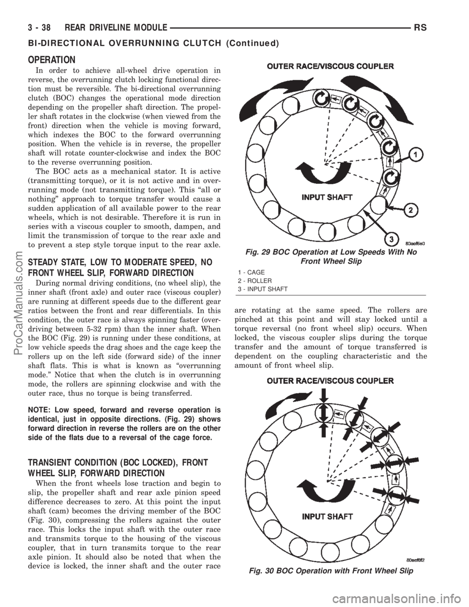
the BOC (Fig. 29) is running under these conditions, at
low vehicle speeds the drag shoes and the cage keep the
rollers up on the left side (forward side) of the inner
shaft flats. This is what is known as ªoverrunning
mode.º Notice that when the clutch is in overrunning
mode, the rollers are spinning clockwise and with the
outer race, thus no torque is being transferred.
NOTE: Low speed, forward and reverse operation is
identical, just in opposite directions. (Fig. 29) shows
forward direction in reverse the rollers are on the other
side of the flats due to a reversal of the cage force.
TRANSIENT CONDITION (BOC LOCKED), FRONT
WHEEL SLIP, FORWARD DIRECTION
When the front wheels lose traction and begin to
slip, the propeller shaft and rear axle pinion speed
difference decreases to zero. At this point the input
shaft (cam) becomes the driving member of the BOC
(Fig. 30), compressing the rollers against the outer
race. This locks the input shaft with the outer race
and transmits torque to the housing of the viscous
coupler, that in turn transmits torque to the rear
axle pinion. It should also be noted that when the
device is locked, the inner shaft and the outer raceare rotating at the same speed. The rollers are
pinched at this point and will stay locked until a
torque reversal (no front wheel slip) occurs. When
locked, the viscous coupler slips during the torque
transfer and the amount of torque transferred is
dependent on the coupling characteristic and the
amount of front wheel slip.
Fig. 29 BOC Operation at Low Speeds With No
Front Wheel Slip
1 - CAGE
2 - ROLLER
3 - INPUT SHAFT
Fig. 30 BOC Operation with Front Wheel Slip
3 - 38 REAR DRIVELINE MODULERS
BI-DIRECTIONAL OVERRUNNING CLUTCH (Continued)
ProCarManuals.com
Page 141 of 2399
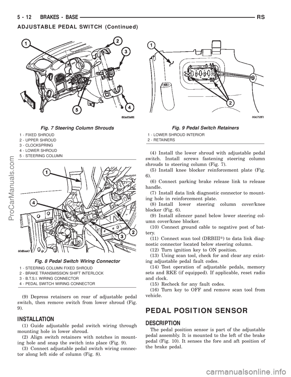
(9) Depress retainers on rear of adjustable pedal
switch, then remove switch from lower shroud (Fig.
9).
INSTALLATION
(1) Guide adjustable pedal switch wiring through
mounting hole in lower shroud.
(2) Align switch retainers with notches in mount-
ing hole and snap the switch into place (Fig. 9).
(3) Connect adjustable pedal switch wiring connec-
tor along left side of column (Fig. 8).(4) Install the lower shroud with adjustable pedal
switch. Install screws fastening steering column
shrouds to steering column (Fig. 7).
(5) Install knee blocker reinforcement plate (Fig.
6).
(6) Connect parking brake release link to release
handle.
(7) Install data link diagnostic connector to mount-
ing hole in reinforcement plate.
(8) Install lower steering column cover/knee
blocker (Fig. 6).
(9) Install silencer panel below lower steering col-
umn cover/knee blocker.
(10) Connect ground cable to negative post of bat-
tery.
(11) Connect scan tool (DRBIIIt) to data link diag-
nostic connector located below steering column.
(12) Turn ignition key to ON position.
(13) Using scan tool, check for and clear any exist-
ing adjustable pedal fault codes.
(14) Test operation of adjustable pedals, memory
sets and RKE (if equipped). If applicable, reset radio
and clock.
(15) Recheck for any fault codes.
(16) Turn key to OFF and remove scan tool from
vehicle.
PEDAL POSITION SENSOR
DESCRIPTION
The pedal position sensor is part of the adjustable
pedal assembly. It is mounted to the left of the brake
pedal (Fig. 10). It senses the fore and aft position of
the brake pedal.
Fig. 7 Steering Column Shrouds
1 - FIXED SHROUD
2 - UPPER SHROUD
3 - CLOCKSPRING
4 - LOWER SHROUD
5 - STEERING COLUMN
Fig. 8 Pedal Switch Wiring Connector
1 - STEERING COLUMN FIXED SHROUD
2 - BRAKE TRANSMISSION SHIFT INTERLOCK
3 - B.T.S.I. WIRING CONNECTOR
4 - PEDAL SWITCH WIRING CONNECTOR
Fig. 9 Pedal Switch Retainers
1 - LOWER SHROUD INTERIOR
2 - RETAINERS
5 - 12 BRAKES - BASERS
ADJUSTABLE PEDAL SWITCH (Continued)
ProCarManuals.com
Page 142 of 2399
DIAGNOSIS AND TESTING - PEDAL POSITION
SENSOR
Refer to Appropriate Diagnostic Information.
REMOVAL
(1) Remove battery ground cable terminal from
battery negative post and isolate.
(2) Under instrument panel, remove silencer panel
below lower steering column cover.
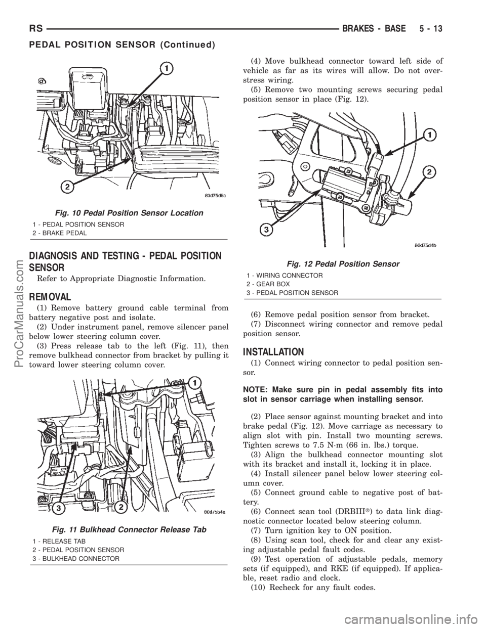
(3) Press release tab to the left (Fig. 11), then
remove bulkhead connector from bracket by pulling it
toward lower steering column cover.(4) Move bulkhead connector toward left side of
vehicle as far as its wires will allow. Do not over-
stress wiring.
(5) Remove two mounting screws securing pedal
position sensor in place (Fig. 12).
(6) Remove pedal position sensor from bracket.
(7) Disconnect wiring connector and remove pedal
position sensor.
INSTALLATION
(1) Connect wiring connector to pedal position sen-
sor.
NOTE: Make sure pin in pedal assembly fits into
slot in sensor carriage when installing sensor.
(2) Place sensor against mounting bracket and into
brake pedal (Fig. 12). Move carriage as necessary to
align slot with pin. Install two mounting screws.
Tighten screws to 7.5 N´m (66 in. lbs.) torque.
(3) Align the bulkhead connector mounting slot
with its bracket and install it, locking it in place.
(4) Install silencer panel below lower steering col-
umn cover.
(5) Connect ground cable to negative post of bat-
tery.
(6) Connect scan tool (DRBIIIt) to data link diag-
nostic connector located below steering column.
(7) Turn ignition key to ON position.
(8) Using scan tool, check for and clear any exist-
ing adjustable pedal fault codes.
(9) Test operation of adjustable pedals, memory
sets (if equipped), and RKE (if equipped). If applica-
ble, reset radio and clock.
(10) Recheck for any fault codes.
Fig. 10 Pedal Position Sensor Location
1 - PEDAL POSITION SENSOR
2 - BRAKE PEDAL
Fig. 11 Bulkhead Connector Release Tab
1 - RELEASE TAB
2 - PEDAL POSITION SENSOR
3 - BULKHEAD CONNECTOR
Fig. 12 Pedal Position Sensor
1 - WIRING CONNECTOR
2 - GEAR BOX
3 - PEDAL POSITION SENSOR
RSBRAKES - BASE5-13
PEDAL POSITION SENSOR (Continued)
ProCarManuals.com
Page 172 of 2399
ing pedal adjustment, the APM will monitor pedal
position sensor voltage. If the APM does not detect
expected voltage change within 3 seconds, it will cut
power to the adjustable pedal motor.
An optional memory feature is available. This
allows storing of one or two preferred pedal positions
in the APS. A preferred position can be stored and
recalled using the door-mounted switches. A stored
pedal position can be recalled (but not stored) using
the Remote Keyless Entry (RKE) if equipped with
the memory feature.
DIAGNOSIS AND TESTING - ADJUSTABLE
PEDAL SYSTEM
Refer to Appropriate Diagnostic Information.
REMOVAL
NOTE: Before proceeding, review all Steering Col-
umn and Airbag Warnings and Cautions. (Refer to
19 - STEERING/COLUMN - WARNING)(Refer to 8 -
ELECTRICAL/RESTRAINTS - WARNING)
(1) Remove battery ground cable terminal from
battery negative post and isolate.
(2) Under instrument panel, remove silencer panel
below lower steering column cover.
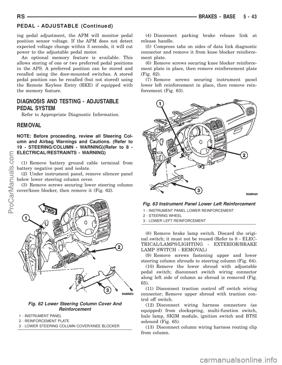
(3) Remove screws securing lower steering column
cover/knee blocker, then remove it (Fig. 62).(4) Disconnect parking brake release link at
release handle.
(5) Compress tabs on sides of data link diagnostic
connector and remove it from knee blocker reinforce-
ment plate.
(6) Remove screws securing knee blocker reinforce-
ment plate in place, then remove reinforcement plate
(Fig. 62).
(7) Remove screws securing instrument panel
lower left reinforcement in place, then remove rein-
forcement (Fig. 63).
(8) Remove brake lamp switch. Discard the origi-
nal switch; it must not be reused (Refer to 8 - ELEC-
TRICAL/LAMPS/LIGHTING - EXTERIOR/BRAKE
LAMP SWITCH - REMOVAL)
(9) Remove screws fastening upper and lower
steering column shrouds to steering column (Fig. 64).
(10) Remove the lower shroud with adjustable
pedal switch; disconnect switch wiring connector
along left side of column as shroud is removed (Fig.
65).
(11) Disconnect traction control off switch wiring
connector; Remove upper shroud with traction con-
trol off switch.
(12) Disconnect wiring harness connectors (as
equipped) from clockspring, multi-function switch,
halo lamp, SKIM module, ignition switch and BTSI
solenoid (Fig. 65).
(13) Disconnect column wiring harness routing clip
from column.
Fig. 62 Lower Steering Column Cover And
Reinforcement
1 - INSTRUMENT PANEL
2 - REINFORCEMENT PLATE
3 - LOWER STEERING COLUMN COVER/KNEE BLOCKER
Fig. 63 Instrument Panel Lower Left Reinforcement
1 - INSTRUMENT PANEL LOWER REINFORCEMENT
2 - STEERING WHEEL
3 - LOWER LEFT REINFORCEMENT
RSBRAKES - BASE5-43
PEDAL - ADJUSTABLE (Continued)
ProCarManuals.com
Page 173 of 2399
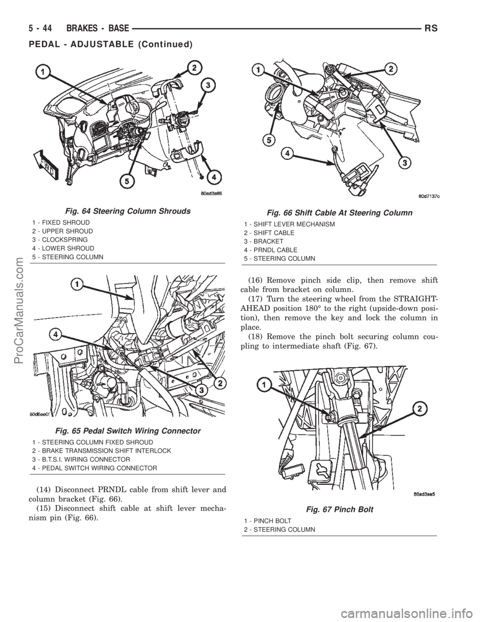
(14) Disconnect PRNDL cable from shift lever and
column bracket (Fig. 66).
(15) Disconnect shift cable at shift lever mecha-
nism pin (Fig. 66).(16) Remove pinch side clip, then remove shift
cable from bracket on column.
(17) Turn the steering wheel from the STRAIGHT-
AHEAD position 180É to the right (upside-down posi-
tion), then remove the key and lock the column in
place.
(18) Remove the pinch bolt securing column cou-
pling to intermediate shaft (Fig. 67).
Fig. 64 Steering Column Shrouds
1 - FIXED SHROUD
2 - UPPER SHROUD
3 - CLOCKSPRING
4 - LOWER SHROUD
5 - STEERING COLUMN
Fig. 65 Pedal Switch Wiring Connector
1 - STEERING COLUMN FIXED SHROUD
2 - BRAKE TRANSMISSION SHIFT INTERLOCK
3 - B.T.S.I. WIRING CONNECTOR
4 - PEDAL SWITCH WIRING CONNECTOR
Fig. 66 Shift Cable At Steering Column
1 - SHIFT LEVER MECHANISM
2 - SHIFT CABLE
3 - BRACKET
4 - PRNDL CABLE
5 - STEERING COLUMN
Fig. 67 Pinch Bolt
1 - PINCH BOLT
2 - STEERING COLUMN
5 - 44 BRAKES - BASERS
PEDAL - ADJUSTABLE (Continued)
ProCarManuals.com