egr valve CHRYSLER VOYAGER 2002 Service Manual
[x] Cancel search | Manufacturer: CHRYSLER, Model Year: 2002, Model line: VOYAGER, Model: CHRYSLER VOYAGER 2002Pages: 2399, PDF Size: 57.96 MB
Page 185 of 2399
the mounting nuts to a torque of 14 N´m (124 in.
lbs.).
(14) Install the battery tray. Install the two nuts
and one bolt attaching the battery tray to the vehicle.
Tighten the bolt and nuts to a torque of 14 N´m (124
in. lbs.).
(15) If vehicle is equipped with speed control, con-
nect the servo vacuum hose to the vacuum tank on
the battery tray.
(16) Install the battery, clamp and mounting nut.
(17) Install the positive battery cable on the bat-
tery.
(18) Install the negative battery cable on the bat-
tery.
(19) Install the battery thermal guard shield.
CAUTION: Do not reuse the original brake lamp
switch. The switch can only be adjusted once. That
is during initial installation of the switch. If the
switch is not adjusted properly or has been
removed for some service, a new switch must be
installed and adjusted.
(20) Remove and replace the brake lamp switch
with a NEW switch. (Refer to 8 - ELECTRICAL/
LAMPS/LIGHTING - EXTERIOR/BRAKE LAMP
SWITCH - REMOVAL), (Refer to 8 - ELECTRICAL/
LAMPS/LIGHTING - EXTERIOR/BRAKE LAMP
SWITCH - INSTALLATION)
(21) Bleed the base brakes as necessary. (Refer to
5 - BRAKES - STANDARD PROCEDURE)
(22) Road test vehicle to ensure proper operation
of the brakes.
PROPORTIONING VALVE
DESCRIPTION - PROPORTIONING VALVE
(HEIGHT SENSING)
NOTE: Only vehicles without antilock brakes (ABS)
have a proportioning valve. Vehicles with ABS uti-
lize electronic brake distribution which is controlled
through the ABS integrated control unit.
Vehicles not equipped with ABS use a height sens-
ing proportioning valve. It is mounted to the body of
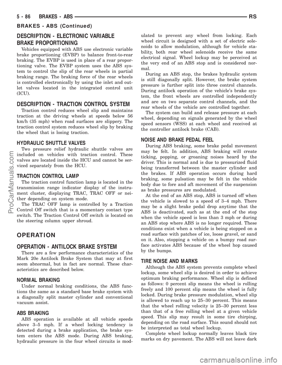
the vehicle above the rear axle (Fig. 91). It has an
actuator lever that attaches to the rear axle and
moves with the axle to help the valve sense the vehi-
cle height.
CAUTION: The height sensing proportioning valve
is not adjustable. No attempt should be made to
adjust it. It is replaced as a complete assembly.
CAUTION: The use of after-market load leveling or
load capacity increasing devices on this vehicle are
prohibited. Using air shock absorbers or helper
springs on this vehicle will cause the height sens-
ing proportioning valve to inappropriately reduce
the hydraulic pressure to the rear brakes. This inap-
propriate reduction in hydraulic pressure potentially
could result in increased stopping distance of the
vehicle.
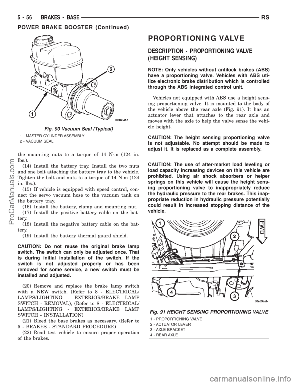
Fig. 90 Vacuum Seal (Typical)
1 - MASTER CYLINDER ASSEMBLY
2 - VACUUM SEAL
Fig. 91 HEIGHT SENSING PROPORTIONING VALVE
1 - PROPORTIONING VALVE
2 - ACTUATOR LEVER
3 - AXLE BRACKET
4 - REAR AXLE
5 - 56 BRAKES - BASERS
POWER BRAKE BOOSTER (Continued)
ProCarManuals.com
Page 214 of 2399

BRAKES - ABS
TABLE OF CONTENTS
page page
BRAKES - ABS
DESCRIPTION
DESCRIPTION - ANTILOCK BRAKE
SYSTEM............................85
DESCRIPTION - ANTILOCK BRAKE
SYSTEM (EXPORT)....................85
DESCRIPTION - ELECTRONIC VARIABLE
BRAKE PROPORTIONING...............86
DESCRIPTION - TRACTION CONTROL
SYSTEM............................86
OPERATION
OPERATION - ANTILOCK BRAKE SYSTEM . . 86
OPERATION - ELECTRONIC VARIABLE
BRAKE PROPORTIONING...............87
OPERATION - TRACTION CONTROL
SYSTEM............................87
CAUTION
CAUTIONS..........................88
STANDARD PROCEDURE - ANTILOCK BRAKE
SYSTEM BLEEDING...................88
SPECIFICATIONS
ABS FASTENER TORQUE...............89
TONE WHEEL RUNOUT................89
WHEEL SPEED SENSOR AIR GAP........89
FRONT WHEEL SPEED SENSOR
REMOVAL.............................89
INSTALLATION.........................89
REAR WHEEL SPEED SENSOR - AWD
REMOVAL.............................90INSTALLATION.........................90
REAR WHEEL SPEED SENSOR - FWD
REMOVAL.............................91
INSTALLATION.........................91
TONE WHEEL
INSPECTION - TONE WHEEL..............92
TRACTION CONTROL SWITCH
DIAGNOSIS AND TESTING - TRACTION
CONTROL SWITCH....................92
HYDRAULIC/MECHANICAL
OPERATION - HYDRAULIC CIRCUITS AND
VALVES .............................93
HCU (HYDRAULIC CONTROL UNIT)
DESCRIPTION.........................99
OPERATION...........................99
ICU (INTEGRATED CONTROL UNIT)
DESCRIPTION........................100
OPERATION..........................100
REMOVAL
REMOVAL - LHD.....................100
REMOVAL - RHD.....................101
DISASSEMBLY - ICU...................103
ASSEMBLY - ICU......................103
INSTALLATION
INSTALLATION - LHD.................104
INSTALLATION - RHD.................105
BRAKES - ABS
DESCRIPTION
DESCRIPTION - ANTILOCK BRAKE SYSTEM
This section covers the physical and operational
descriptions and the on-car service procedures for the
Mark 20e Antilock Brake System and the Mark 20e
Antilock Brake System with traction control.
The purpose of the antilock brake system (ABS) is
to prevent wheel lockup under braking conditions on
virtually any type of road surface. Antilock braking is
desirable because a vehicle that is stopped without
locking the wheels retains directional stability and
some steering capability. This allows the driver to
retain greater control of the vehicle during braking.
DESCRIPTION - ANTILOCK BRAKE SYSTEM
(EXPORT)
Four-wheel disc antilock brakes are standard on all
models. The Mark 20e antilock brake system is used
on all models. Depending on whether the vehicle is a
left-hand drive (LHD) or right-hand drive (RHD)
model, the integrated control unit (ICU) is located in
one of two locations. On LHD models, the ICU is
mounted above the front suspension cradle/cross-
member below the master cylinder. On RHD models,
the ICU is located behind the front suspension cra-
dle/crossmember on the left side of the vehicle.
RSBRAKES - ABS5-85
ProCarManuals.com
Page 215 of 2399
DESCRIPTION - ELECTRONIC VARIABLE
BRAKE PROPORTIONING
Vehicles equipped with ABS use electronic variable
brake proportioning (EVBP) to balance front-to-rear
braking. The EVBP is used in place of a rear propor-
tioning valve. The EVBP system uses the ABS sys-
tem to control the slip of the rear wheels in partial
braking range. The braking force of the rear wheels
is controlled electronically by using the inlet and out-
let valves located in the integrated control unit
(ICU).
DESCRIPTION - TRACTION CONTROL SYSTEM
Traction control reduces wheel slip and maintains
traction at the driving wheels at speeds below 56
km/h (35 mph) when road surfaces are slippery. The
traction control system reduces wheel slip by braking
the wheel that is losing traction.
HYDRAULIC SHUTTLE VALVES
Two pressure relief hydraulic shuttle valves are
included on vehicles with traction control. These
valves are located inside the HCU and cannot be ser-
viced separately from the HCU.
TRACTION CONTROL LAMP
The traction control function lamp is located in the
transmission range indicator display of the instru-
ment cluster, displaying TRAC, TRAC OFF or nei-
ther depending on system mode.
The TRAC OFF lamp is controlled by a Traction
Control Off switch that is a momentary contact type
switch. The Traction Control Off switch is located on
the steering column upper shroud.
OPERATION
OPERATION - ANTILOCK BRAKE SYSTEM
There are a few performance characteristics of the
Mark 20e Antilock Brake System that may at first
seem abnormal, but in fact are normal. These char-
acteristics are described below.
NORMAL BRAKING
Under normal braking conditions, the ABS func-
tions the same as a standard base brake system with
a diagonally split master cylinder and conventional
vacuum assist.
ABS BRAKING
ABS operation is available at all vehicle speeds
above 3±5 mph. If a wheel locking tendency is
detected during a brake application, the brake sys-
tem enters the ABS mode. During ABS braking,
hydraulic pressure in the four wheel circuits is mod-ulated to prevent any wheel from locking. Each
wheel circuit is designed with a set of electric sole-
noids to allow modulation, although for vehicle sta-
bility, both rear wheel solenoids receive the same
electrical signal. Wheel lockup may be perceived at
the very end of an ABS stop and is considered nor-
mal.
During an ABS stop, the brakes hydraulic system
is still diagonally split. However, the brake system
pressure is further split into three control channels.
During antilock operation of the vehicle's brake sys-
tem, the front wheels are controlled independently
and are on two separate control channels, and the
rear wheels of the vehicle are controlled together.
The system can build and release pressure at each
wheel, depending on signals generated by the wheel
speed sensors (WSS) at each wheel and received at
the controller antilock brake (CAB).
NOISE AND BRAKE PEDAL FEEL
During ABS braking, some brake pedal movement
may be felt. In addition, ABS braking will create
ticking, popping, or groaning noises heard by the
driver. This is normal and is due to pressurized fluid
being transferred between the master cylinder and
the brakes. If ABS operation occurs during hard
braking, some pulsation may be felt in the vehicle
body due to fore and aft movement of the suspension
as brake pressures are modulated.
At the end of an ABS stop, ABS is turned off when
the vehicle is slowed to a speed of 3±4 mph. There
may be a slight brake pedal drop anytime that the
ABS is deactivated, such as at the end of the stop
when the vehicle speed is less than 3 mph or during
an ABS stop where ABS is no longer required. These
conditions exist when a vehicle is being stopped on a
road surface with patches of ice, loose gravel, or sand
on it. Also, stopping a vehicle on a bumpy road sur-
face activates ABS because of the wheel hop caused
by the bumps.
TIRE NOISE AND MARKS
Although the ABS system prevents complete wheel
lockup, some wheel slip is desired in order to achieve
optimum braking performance. Wheel slip is defined
as follows: 0 percent slip means the wheel is rolling
freely and 100 percent slip means the wheel is fully
locked. During brake pressure modulation, wheel slip
is allowed to reach up to 25±30 percent. This means
that the wheel rolling velocity is 25±30 percent less
than that of a free rolling wheel at a given vehicle
speed. This slip may result in some tire chirping,
depending on the road surface. This sound should not
be interpreted as total wheel lockup.
Complete wheel lockup normally leaves black tire
marks on dry pavement. The ABS will not leave dark
5 - 86 BRAKES - ABSRS
BRAKES - ABS (Continued)
ProCarManuals.com
Page 228 of 2399

HCU (HYDRAULIC CONTROL
UNIT)
DESCRIPTION
The hydraulic control unit (HCU) is mounted to
the CAB as part of the ICU (Fig. 22). The HCU con-
trols the flow of brake fluid to the brakes using a
series of valves and accumulators. A pump/motor is
mounted on the HCU to supply build pressure to the
brakes during an ABS stop.
The HCU on a vehicle equipped with ABS and
traction control has a valve block housing that is
approximately 1 inch longer on the low pressure fluid
accumulators side than a HCU on a vehicle that is
equipped with only ABS.
For more information, (Refer to 5 - BRAKES/HY-
DRAULIC/MECHANICAL/ICU (INTEGRATED CON-
TROL UNIT) - DESCRIPTION)
OPERATION
For information on the operation of the HCU as a
whole, refer to Hydraulic Circuits And Valve Opera-
tion which can be found elsewhere in this section.
For information on the operation of the components
within the HCU, refer to the following three topics.
VALVES AND SOLENOIDS
The valve block contains four inlet valves and four
outlet valves. The inlet valves are spring-loaded in
the open position and the outlet valves are spring-
loaded in the closed position during normal braking.
The fluid is allowed to flow from the master cylinder
to the wheel brakes.
During an ABS stop, these valves cycle to maintain
the proper slip ratio for each wheel. The inlet valve
closes preventing further pressure increase and the
outlet valve opens to provide a path from the wheel
brake to the HCU accumulators and pump/motor.
This releases (decays) pressure from the wheel brake,
thus releasing the wheel from excessive slippage.
Once the wheel is no longer slipping, the outlet valve
is closed and the inlet valve is opened to reapply
(build) pressure.
On vehicles with traction control, there is an extra
set of valves and solenoids. The ASR valves, mounted
in the HCU valve block, are normally in the open
position and close only when the traction control is
applied.
These isolator valves are used to isolate the rear
(non-driving) wheels of the vehicle from the hydraulicpressure that the HCU pump/motor is sending to the
front (driving) wheels when traction control is being
applied. The rear brakes need to be isolated from the
master cylinder when traction control is being
applied so the rear wheels do not drag. For more
information, refer to Traction Control System in this
section.
BRAKE FLUID ACCUMULATORS
There are two fluid accumulators in the HCU±one
for the primary hydraulic circuit and one for the sec-
ondary hydraulic circuit. Each hydraulic circuit uses
a 5 cc accumulator.
The fluid accumulators temporarily store brake
fluid that is removed from the wheel brakes during
an ABS cycle. This stored fluid is used by the pump/
motor to provide build pressure for the brake hydrau-
lic system. When the antilock stop is complete, the
accumulators are drained by the pump/motor.
On ABS-only vehicles, there is a mini-accumulator
on the secondary hydraulic circuit that protects the
master cylinder seals during an ABS stop, and there
is a noise dampening chamber on the primary circuit.
On ABS with traction control vehicles, there are
two noise dampening chambers in the HCU.
PUMP/MOTOR
There are two pump assemblies in the HCUÐone
for the primary hydraulic circuit and one for the sec-
ondary hydraulic circuit. Both pumps are driven by a
common electric motor. This DC-type motor is inte-
gral to the HCU and is controlled by the CAB.
The pump/motor provides the extra amount of
brake fluid needed during antilock braking. Brake
fluid is released to the accumulators when the outlet
valve is opened during an antilock stop. The pump
mechanism consists of two opposing pistons operated
by an eccentric camshaft. In operation, one piston
draws fluid from the accumulators, and the opposing
piston pumps fluid to the master cylinder circuits.
When the antilock stop is complete, the pump/motor
drains the accumulators.
The CAB may turn on the pump/motor when an
antilock stop is detected. The pump/motor continues
to run during the antilock stop and is turned off after
the stop is complete. Under some conditions, the
pump/motor runs to drain the accumulators during
the next drive-off.
The pump/motor is not a serviceable item; if it
requires replacement, the HCU must be replaced.
RSBRAKES - ABS5-99
ProCarManuals.com
Page 229 of 2399

ICU (INTEGRATED CONTROL
UNIT)
DESCRIPTION
The hydraulic control unit (HCU) and the control-
ler antilock brake (CAB) used with this antilock
brake system are combined (integrated) into one
unit, which is called the integrated control unit (ICU)
(Fig. 12). The ICU is located below the master cylin-
der in the engine compartment (Fig. 13).Two different ICU's (HCU and CAB) are used on
this vehicle depending on whether or not the vehicle
is equipped with traction control. The HCU on a
vehicle equipped with traction control has a valve
block that is approximately one inch longer than a
HCU on a vehicle that is equipped with ABS only.
The ABS-only ICU consists of the following compo-
nents: the CAB, eight (build/decay) solenoid valves
(four inlet valves and four outlet valves), valve block,
fluid accumulators, a pump, and an electric motor.
The ABS-with traction control ICU consists of the
following components: the CAB, eight (build/decay)
solenoid valves (four inlet valves and four outlet
valves), two traction control (ASR) valves, two
hydraulic shuttle valves, valve block, fluid accumula-
tors, a pump, and an electric motor.
The replaceable components of the ICU are the
HCU and the CAB. No attempt should be made to
service any individual components of the HCU or
CAB. For information on the CAB, (Refer to 8 -
ELECTRICAL/ELECTRONIC CONTROL MOD-
ULES/CONTROLLER ANTILOCK BRAKE -
DESCRIPTION).
OPERATION
For information of the ICU, refer to these individ-
ual components of the ICU:
²CONTROLLER ANTILOCK BRAKE (CAB)
(Refer to 8 - ELECTRICAL/ELECTRONIC CON-
TROL MODULES/CONTROLLER ANTILOCK
BRAKE - OPERATION)
²HYDRAULIC CONTROL UNIT (HCU) (Refer to
5 - BRAKES - ABS/HYDRAULIC/MECHANICAL/
HCU (HYDRAULIC CONTROL UNIT) - OPERA-
TION)
For information on the ICU's hydraulic circuits,
refer to HYDRAULIC CIRCUITS AND VALVE
OPERATION. (Refer to 5 - BRAKES - ABS/HY-
DRAULIC/MECHANICAL - OPERATION)
REMOVAL
REMOVAL - LHD
(1) Disconnect the negative (ground) cable from
the battery and isolate cable.
(2) Remove the battery shield.
(3) Remove the battery (Refer to 8 - ELECTRI-
CAL/BATTERY SYSTEM/BATTERY - REMOVAL).
(4) Disconnect the vacuum hose connector at the
tank built into the battery tray.
(5) Remove the screw securing the engine coolant
filler neck to the battery tray.
(6) Remove the battery tray (Refer to 8 - ELEC-
TRICAL/BATTERY SYSTEM/TRAY - REMOVAL).
Fig. 12 INTEGRATED CONTROL UNIT (ICU)
1 - PUMP/MOTOR
2 - HCU
3 - PUMP/MOTOR CONNECTOR
4 - CAB
Fig. 13 ICU LOCATION IN VEHICLE
1 - POWER BRAKE BOOSTER
2 - MASTER CYLINDER
3 - ICU
5 - 100 BRAKES - ABSRS
ProCarManuals.com
Page 233 of 2399
INSTALLATION
INSTALLATION - LHD
(1) Place the ICU in its bracket below the master
cylinder. Start the upper mounting bolt to hold it in
place.
(2) Inside the vehicle, install the remaining 2
mounting bolts attaching the ICU to the mounting
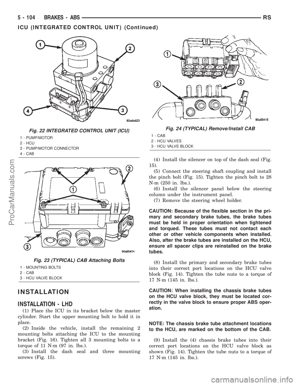
bracket (Fig. 16). Tighten all 3 mounting bolts to a
torque of 11 N´m (97 in. lbs.).
(3) Install the dash seal and three mounting
screws (Fig. 15).(4) Install the silencer on top of the dash seal (Fig.
15).
(5) Connect the steering shaft coupling and install
the pinch bolt (Fig. 15). Tighten the pinch bolt to 28
N´m (250 in. lbs.).
(6) Install the silencer panel below the steering
column under the instrument panel.
(7) Remove the steering wheel holder.
CAUTION: Because of the flexible section in the pri-
mary and secondary brake tubes, the brake tubes
must be held in proper orientation when tightened
and torqued. These tubes must not contact each
other or other vehicle components when installed.
Also, after the brake tubes are installed on the HCU,
ensure all spacer clips are reinstalled on the brake
tubes.
(8) Install the primary and secondary brake tubes
into their correct port locations on the HCU valve
block (Fig. 14). Tighten the tube nuts to a torque of
17 N´m (145 in. lbs.).
CAUTION: When installing the chassis brake tubes
on the HCU valve block, they must be located cor-
rectly in the valve block to ensure proper ABS oper-
ation.
NOTE: The chassis brake tube attachment locations
to the HCU, are marked on the bottom of the CAB.
(9) Install the (4) chassis brake tubes into their
correct port locations on the HCU valve block as
shown (Fig. 14). Tighten the tube nuts to a torque of
17 N´m (145 in. lbs.).
Fig. 22 INTEGRATED CONTROL UNIT (ICU)
1 - PUMP/MOTOR
2 - HCU
3 - PUMP/MOTOR CONNECTOR
4 - CAB
Fig. 23 (TYPICAL) CAB Attaching Bolts
1 - MOUNTING BOLTS
2 - CAB
3 - HCU VALVE BLOCK
Fig. 24 (TYPICAL) Remove/Install CAB
1 - CAB
2 - HCU VALVES
3 - HCU VALVE BLOCK
5 - 104 BRAKES - ABSRS
ICU (INTEGRATED CONTROL UNIT) (Continued)
ProCarManuals.com
Page 234 of 2399
NOTE: Before installing the 24±way connector in
the CAB be sure the seal is properly installed in the
connector.
(10) Install the 24±way connector on the CAB by,
first, positioning the 24±way connector in the socket
of the CAB and carefully pushing it down as far as
possible. Once connector is fully seated by hand into
the CAB socket, push down on connector lock. This
will pull the connector into the socket of the CAB
and lock it in the installed position.
(11) Install any routing clips on the brake tubes.
(12) Remove the brake pedal holder.
(13) Install the speed control servo with its mount-
ing nuts.
(14) Connect the wiring harness to the speed con-
trol servo.
(15) Install the battery tray (Refer to 8 - ELEC-
TRICAL/BATTERY SYSTEM/TRAY - INSTALLA-
TION).
(16) Install the screw securing the coolant filler
neck to the battery tray.
(17) Reconnect the vacuum hose connector at the
tank built into the battery tray.
(18) Install the battery (Refer to 8 - ELECTRI-
CAL/BATTERY SYSTEM/BATTERY - INSTALLA-
TION).
(19) Install the battery shield.
(20) Remove the brake pedal holder.
(21) Connect negative cable back on negative post
of the battery.
(22) Bleed the Base and ABS brake hydraulic sys-
tems (Refer to 5 - BRAKES - STANDARD PROCE-
DURE).
(23) Road test vehicle to ensure proper operation
of the base and antilock brake systems.
INSTALLATION - RHD
(1) Install the ICU on the mounting bracket (Fig.
21). Install the 3 bolts (Fig. 21) attaching the ICU to
the mounting bracket. Tighten the 3 mounting bolts
to a torque of 11 N´m (97 in. lbs.).
CAUTION: The ICU mounting bracket to front sus-
pension cradle mounting bolts have a unique corro-
sion protection coating and a special aluminum
washer. For this reason, only the original, or origi-
nal equipment Mopar replacement bolts can be
used to mount the ICU bracket to the front suspen-
sion crossmember.(2) Install the ICU and its mounting bracket as an
assembly on the front suspension crossmember.
Install the 3 bolts attaching the ICU bracket to the
crossmember (Fig. 20). Tighten the 3 mounting bolts
to a torque of 28 N´m (250 in. lbs.).
CAUTION: Because of the flexible section in the pri-
mary and secondary brake tubes, and the brake
tubes between the HCU and the proportioning
valve, the brake tubes must be held in proper ori-
entation when tightened and torqued. These tubes
must not contact each other or other vehicle com-
ponents when installed. Also, after the brake tubes
are installed on the HCU, ensure all spacer clips are
reinstalled on the brake tubes.
CAUTION: When installing the chassis brake tubes
on the HCU valve block, they must be located cor-
rectly in the valve block to ensure proper ABS oper-
ation. Refer to (Fig. 19) for the correct chassis
brake tube locations.
NOTE: The chassis brake tube attachment locations
to the HCU, are marked on the bottom of the ICU
mounting bracket.
(3) Install the 6 chassis brake tubes into their cor-
rect port locations on the HCU valve block as shown
in (Fig. 19). Tighten the tube nuts to a torque of 17
N´m (145 in. lbs.).
NOTE: Before installing the 24-way connector in the
CAB be sure the seal is properly installed in the
connector.
(4) Install the 24-way connector (Fig. 17) on the
CAB using the following procedure. Position the
24-way connector in the socket of the CAB and care-
fully push it down as far as possible. When connector
is fully seated by hand into the CAB socket, push in
the connector lock (Fig. 18). This will pull the connec-
tor into the socket of the CAB and lock it in the
installed position.
NOTE: The CAB wiring harness must be clipped to
the ICU mounting bracket. This will ensure the wir-
ing harness is properly routed and does not contact
the brake tubes or the body of the vehicle.
RSBRAKES - ABS5 - 105
ICU (INTEGRATED CONTROL UNIT) (Continued)
ProCarManuals.com
Page 312 of 2399
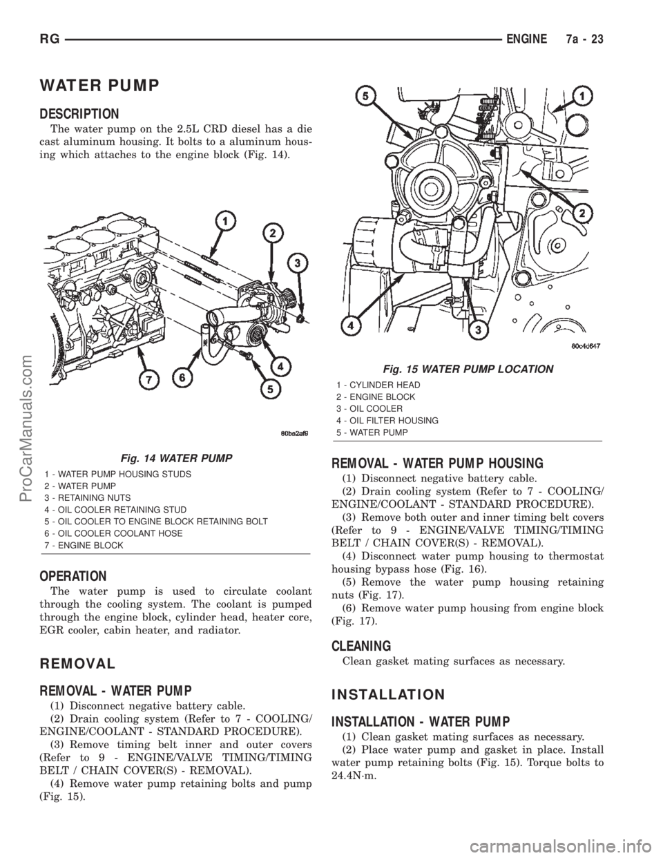
WATER PUMP
DESCRIPTION
The water pump on the 2.5L CRD diesel has a die
cast aluminum housing. It bolts to a aluminum hous-
ing which attaches to the engine block (Fig. 14).
OPERATION
The water pump is used to circulate coolant
through the cooling system. The coolant is pumped
through the engine block, cylinder head, heater core,
EGR cooler, cabin heater, and radiator.
REMOVAL
REMOVAL - WATER PUMP
(1) Disconnect negative battery cable.
(2) Drain cooling system (Refer to 7 - COOLING/
ENGINE/COOLANT - STANDARD PROCEDURE).
(3) Remove timing belt inner and outer covers
(Refer to 9 - ENGINE/VALVE TIMING/TIMING
BELT / CHAIN COVER(S) - REMOVAL).
(4) Remove water pump retaining bolts and pump
(Fig. 15).
REMOVAL - WATER PUMP HOUSING
(1) Disconnect negative battery cable.
(2) Drain cooling system (Refer to 7 - COOLING/
ENGINE/COOLANT - STANDARD PROCEDURE).
(3) Remove both outer and inner timing belt covers
(Refer to 9 - ENGINE/VALVE TIMING/TIMING
BELT / CHAIN COVER(S) - REMOVAL).
(4) Disconnect water pump housing to thermostat
housing bypass hose (Fig. 16).
(5) Remove the water pump housing retaining
nuts (Fig. 17).
(6) Remove water pump housing from engine block
(Fig. 17).
CLEANING
Clean gasket mating surfaces as necessary.
INSTALLATION
INSTALLATION - WATER PUMP
(1) Clean gasket mating surfaces as necessary.
(2) Place water pump and gasket in place. Install
water pump retaining bolts (Fig. 15). Torque bolts to
24.4N´m.
Fig. 14 WATER PUMP
1 - WATER PUMP HOUSING STUDS
2 - WATER PUMP
3 - RETAINING NUTS
4 - OIL COOLER RETAINING STUD
5 - OIL COOLER TO ENGINE BLOCK RETAINING BOLT
6 - OIL COOLER COOLANT HOSE
7 - ENGINE BLOCK
Fig. 15 WATER PUMP LOCATION
1 - CYLINDER HEAD
2 - ENGINE BLOCK
3 - OIL COOLER
4 - OIL FILTER HOUSING
5 - WATER PUMP
RGENGINE7a-23
ProCarManuals.com
Page 349 of 2399
²Ignition sense
²Intake Air Temperature Sensor
²Knock Sensor
²Leak Detection Pump Feedback
²Manifold Absolute Pressure (MAP) Sensor
²Park/Neutral (from transmission control module)
²PCI Bus
²Power Steering Pressure Switch
²Proportional Purge Sense
²SCI Receive
²Speed Control
²Throttle Position Sensor
²Torque Management Input (From TCM)
²Transaxle Control Module (TCM)
²Transaxle Gear Engagement (From TCM)
²Vehicle Speed (from transmission control mod-
ule)
NOTE: PCM Outputs:
²Air Conditioning Clutch Relay
²Automatic Shut Down (ASD) and Fuel Pump
Relays
²Data Link Connector (PCI and SCI Transmit)
²Double Start Override
²EGR Solenoid
²Fuel Injectors
²Generator Field
²High Speed Fan Relay
²Idle Air Control Motor
²Ignition Coils
²Leak Detection Pump
²Low Speed Fan Relay
²MTV Actuator
²Proportional Purge Solenoid
²SRV Valve
²Speed Control Relay
²Speed Control Vent Relay
²Speed Control Vacuum Relay
²8 Volt Output
²5 Volt Output
Based on inputs it receives, the powertrain control
module (PCM) adjusts fuel injector pulse width, idle
speed, ignition timing, and canister purge operation.
The PCM regulates the cooling fans, air conditioning
and speed control systems. The PCM changes gener-
ator charge rate by adjusting the generator field.
The PCM adjusts injector pulse width (air-fuel
ratio) based on the following inputs.
²Battery Voltage
²Intake Air Temperature Sensor
²Engine Coolant Temperature
²Engine Speed (crankshaft position sensor)²Exhaust Gas Oxygen Content (heated oxygen
sensors)
²Manifold Absolute Pressure
²Throttle Position
The PCM adjusts engine idle speed through the
idle air control motor based on the following inputs.
²Brake Switch
²Engine Coolant Temperature
²Engine Speed (crankshaft position sensor)
²Park/Neutral (transmission gear selection)
²Transaxle Gear Engagement
²Throttle Position
²Vehicle Speed (from Transmission Control Mod-
ule)
The PCM adjusts ignition timing based on the fol-
lowing inputs.
²Intake Air Temperature
²Engine Coolant Temperature
²Engine Speed (crankshaft position sensor)
²Knock Sensor
²Manifold Absolute Pressure
²Park/Neutral (transmission gear selection)
²Transaxle Gear Engagement
²Throttle Position
The automatic shut down (ASD) and fuel pump
relays are mounted externally, but turned on and off
by the powertrain control module through the same
circuit.
The camshaft and crankshaft signals are sent to
the powertrain control module. If the PCM does not
receive both signals within approximately one second
of engine cranking, it deactivates the ASD and fuel
pump relays. When these relays are deactivated,
power is shut off to the fuel injectors, ignition coils,
fuel pump and the heating element in each oxygen
sensor.
The PCM contains a voltage converter that
changes battery voltage to a regulated 8.0 volts. The
8.0 volts power the camshaft position sensor, crank-
shaft position sensor and vehicle speed sensor. The
PCM also provides a 5.0 volts supply for the engine
coolant temperature sensor, intake air temperature
sensor, manifold absolute pressure sensor and throt-
tle position sensor.
The PCM engine control strategy prevents reduced
idle speeds until after the engine operates for 320 km
(200 miles). If the PCM is replaced after 320 km (200
miles) of usage, update the mileage in new PCM. Use
the DRB scan tool to change the mileage in the PCM.
Refer to the appropriate Powertrain Diagnostic Man-
ual and the DRB scan tool.
8E - 12 ELECTRONIC CONTROL MODULESRS
POWERTRAIN CONTROL MODULE (Continued)
ProCarManuals.com
Page 362 of 2399

(M) Check Engine Lamp (MIL) will illuminate during engine operation if this Diagnostic Trouble Code was recorded.
(G) Generator Lamp Illuminated
GENERIC
SCAN TOOL
CODEDRB SCAN TOOL DISPLAY DESCRIPTION OF DIAGNOSTIC TROUBLE CODE
P2008 Short Runner Valve Solenoid Circuit An open or shorted condition detected in the short runner
tuning valve control circuit.
P2302 Ignition Coil Secondary #1 Circuit
P2305 Ignition Coil Secondary #2 Circuit
P2308 Ignition Coil Secondary #3 Circuit
P2311 Ignition Coil Secondary #4 Circuit
P2314 Ignition Coil Secondary #5 Circuit
P2317 Ignition Coil Secondary #6 Circuit
P2320 Ignition Coil Secondary #7 Circuit
P2323 Ignition Coil Secondary #8 Circuit
P2503 Charging System Voltage Low Charging system voltage below minimum acceptable voltage.
OPERATION - SENSOR RETURN - PCM INPUT
The sensor return circuit provides a low electrical
noise ground reference for all of the systems sensors.
The sensor return circuit connects to internal ground
circuits within the Powertrain Control Module (PCM).
OPERATION - SCI RECEIVE - PCM INPUT
SCI Receive is the serial data communication
receive circuit for the DRB scan tool. The Powertrain
Control Module (PCM) receives data from the DRB
through the SCI Receive circuit.
OPERATION - IGNITION SENSE - PCM INPUT
The ignition sense input informs the Powertrain
Control Module (PCM) that the ignition switch is in
the crank or run position.
OPERATION - PCM GROUND
Ground is provided through multiple pins of the
PCM connector. Depending on the vehicle there may
be as many as three different ground pins. There are
power grounds and sensor grounds.
The power grounds are used to control the ground
side of any relay, solenoid, ignition coil or injector.
The signal ground is used for any input that uses
sensor return for ground, and the ground side of any
internal processing component.
The SBEC III case is shielded to prevent RFI and
EMI. The PCM case is grounded and must be firmly
attached to a good, clean body ground.
Internally all grounds are connected together, how-
ever there is noise suppression on the sensor ground.
For EMI and RFI protection the case is also
grounded separately from the ground pins.
OPERATION
OPERATION - 8-VOLT SUPPLY - PCM OUTPUT
The PCM supplies 8 volts to the crankshaft posi-
tion sensor, camshaft position sensor.
OPERATION - 5 VOLT SUPPLY - PCM OUTPUT
The PCM supplies 5 volts to the following sensors:
²A/C pressure transducer
²Engine coolant temperature sensor
²Manifold absolute pressure sensor
²Throttle position sensor
²Linear EGR solenoid
²Battery temperature
²Knock sensor
STANDARD PROCEDURE - OBTAINING
DIAGNOSTIC TROUBLE CODES
BULB CHECK
Key on: Bulb illuminated until vehicle starts, as
long as all once per trip (readiness) monitors com-
pleted. If monitors havenotbeen completed, then:
Key on: bulb check for about 8 seconds, lamp then
flashes if once per trip (readiness) monitors havenot
been completed until vehicle is started, then MIL is
extinguished.
OBTAINING DTC'S USING DRB SCAN TOOL
(1) Connect the DRB scan tool to the data link
(diagnostic) connector. This connector is located in
the passenger compartment; at the lower edge of
instrument panel; near the steering column.
RSELECTRONIC CONTROL MODULES8E-25
POWERTRAIN CONTROL MODULE (Continued)
ProCarManuals.com