ipm CHRYSLER VOYAGER 2002 Service Manual
[x] Cancel search | Manufacturer: CHRYSLER, Model Year: 2002, Model line: VOYAGER, Model: CHRYSLER VOYAGER 2002Pages: 2399, PDF Size: 57.96 MB
Page 21 of 2399
(2) When using another vehicle as a booster
source, park the booster vehicle within cable reach.
Turn off all accessories, set the parking brake, place
the automatic transmission in PARK or the manual
transmission in NEUTRAL and turn the ignition
OFF.
(3) On disabled vehicle, place gear selector in park
or neutral and set park brake. Turn off all accesso-
ries.
(4) Connect jumper cables to booster battery. RED
clamp to positive terminal (+). BLACK clamp to neg-
ative terminal (-). DO NOT allow clamps at opposite
end of cables to touch, electrical arc will result.
Review all warnings in this procedure.
(5) On disabled vehicle, connect RED jumper cable
clamp to positive (+) terminal. Connect BLACK
jumper cable clamp to engine ground as close to the
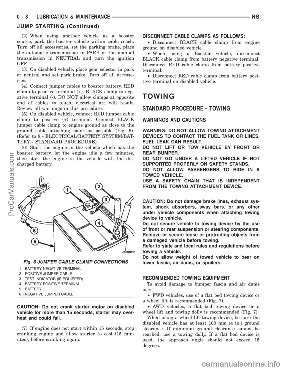
ground cable attaching point as possible (Fig. 6).
(Refer to 8 - ELECTRICAL/BATTERY SYSTEM/BAT-
TERY - STANDARD PROCEDURE).
(6) Start the engine in the vehicle which has the
booster battery, let the engine idle a few minutes,
then start the engine in the vehicle with the dis-
charged battery.
CAUTION: Do not crank starter motor on disabled
vehicle for more than 15 seconds, starter may over-
heat and could fail.
(7) If engine does not start within 15 seconds, stop
cranking engine and allow starter to cool (15 min-
utes), before cranking again.DISCONNECT CABLE CLAMPS AS FOLLOWS:
²Disconnect BLACK cable clamp from engine
ground on disabled vehicle.
²When using a Booster vehicle, disconnect
BLACK cable clamp from battery negative terminal.
Disconnect RED cable clamp from battery positive
terminal.
²Disconnect RED cable clamp from battery posi-
tive terminal on disabled vehicle.
TOWING
STANDARD PROCEDURE - TOWING
WARNINGS AND CAUTIONS
WARNING: DO NOT ALLOW TOWING ATTACHMENT
DEVICES TO CONTACT THE FUEL TANK OR LINES,
FUEL LEAK CAN RESULT.
DO NOT LIFT OR TOW VEHICLE BY FRONT OR
REAR BUMPER.
DO NOT GO UNDER A LIFTED VEHICLE IF NOT
SUPPORTED PROPERLY ON SAFETY STANDS.
DO NOT ALLOW PASSENGERS TO RIDE IN A
TOWED VEHICLE.
USE A SAFETY CHAIN THAT IS INDEPENDENT
FROM THE TOWING ATTACHMENT DEVICE.
CAUTION: Do not damage brake lines, exhaust sys-
tem, shock absorbers, sway bars, or any other
under vehicle components when attaching towing
device to vehicle.
Do not secure vehicle to towing device by the use
of front or rear suspension or steering components.
Remove or secure loose or protruding objects from
a damaged vehicle before towing.
Refer to state and local rules and regulations before
towing a vehicle.
Do not allow weight of towed vehicle to bear on
lower fascia, air dams, or spoilers.
RECOMMENDED TOWING EQUIPMENT
To avoid damage to bumper fascia and air dams
use:
²FWD vehicles, use of a flat bed towing device or
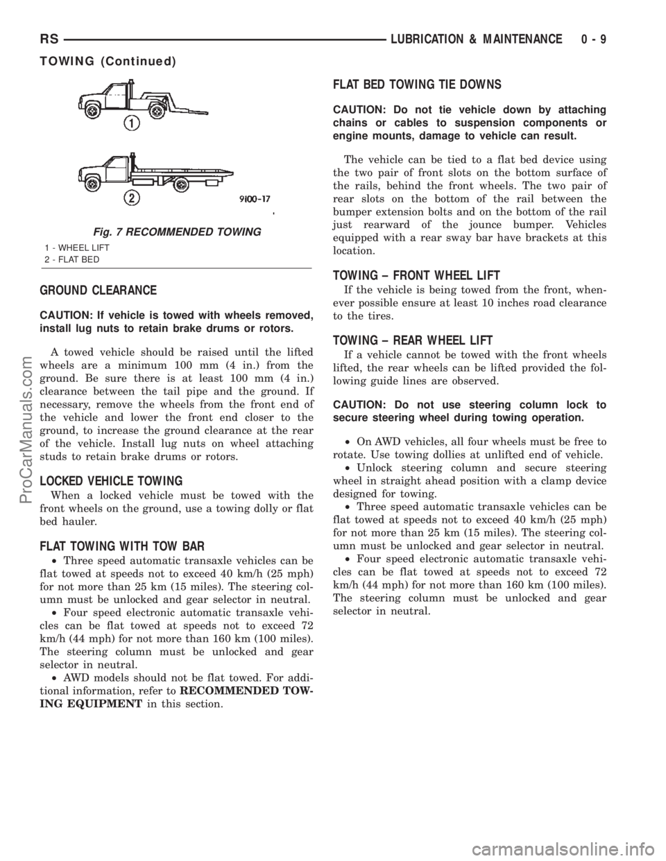
a wheel lift is recommended (Fig. 7).
²AWD vehicles, a flat bed towing device or a
wheel lift and towing dolly is recommended (Fig. 7).
When using a wheel lift towing device, be sure the
disabled vehicle has at least 100 mm (4 in.) ground
clearance. If minimum ground clearance cannot be
reached, use a towing dolly. If a flat bed device is
used, the approach angle should not exceed 15
degrees.
Fig. 6 JUMPER CABLE CLAMP CONNECTIONS
1 - BATTERY NEGATIVE TERMINAL
2 - POSITIVE JUMPER CABLE
3 - TEST INDICATOR (IF EQUIPPED)
4 - BATTERY POSITIVE TERMINAL
5 - BATTERY
6 - NEGATIVE JUMPER CABLE
0 - 8 LUBRICATION & MAINTENANCERS
JUMP STARTING (Continued)
ProCarManuals.com
Page 22 of 2399
GROUND CLEARANCE
CAUTION: If vehicle is towed with wheels removed,
install lug nuts to retain brake drums or rotors.
A towed vehicle should be raised until the lifted
wheels are a minimum 100 mm (4 in.) from the
ground. Be sure there is at least 100 mm (4 in.)
clearance between the tail pipe and the ground. If
necessary, remove the wheels from the front end of
the vehicle and lower the front end closer to the
ground, to increase the ground clearance at the rear
of the vehicle. Install lug nuts on wheel attaching
studs to retain brake drums or rotors.
LOCKED VEHICLE TOWING
When a locked vehicle must be towed with the
front wheels on the ground, use a towing dolly or flat
bed hauler.
FLAT TOWING WITH TOW BAR
²Three speed automatic transaxle vehicles can be
flat towed at speeds not to exceed 40 km/h (25 mph)
for not more than 25 km (15 miles). The steering col-
umn must be unlocked and gear selector in neutral.
²Four speed electronic automatic transaxle vehi-
cles can be flat towed at speeds not to exceed 72
km/h (44 mph) for not more than 160 km (100 miles).
The steering column must be unlocked and gear
selector in neutral.
²AWD models should not be flat towed. For addi-
tional information, refer toRECOMMENDED TOW-
ING EQUIPMENTin this section.
FLAT BED TOWING TIE DOWNS
CAUTION: Do not tie vehicle down by attaching
chains or cables to suspension components or
engine mounts, damage to vehicle can result.
The vehicle can be tied to a flat bed device using
the two pair of front slots on the bottom surface of
the rails, behind the front wheels. The two pair of
rear slots on the bottom of the rail between the
bumper extension bolts and on the bottom of the rail
just rearward of the jounce bumper. Vehicles
equipped with a rear sway bar have brackets at this
location.
TOWING ± FRONT WHEEL LIFT
If the vehicle is being towed from the front, when-
ever possible ensure at least 10 inches road clearance
to the tires.
TOWING ± REAR WHEEL LIFT
If a vehicle cannot be towed with the front wheels
lifted, the rear wheels can be lifted provided the fol-
lowing guide lines are observed.
CAUTION: Do not use steering column lock to
secure steering wheel during towing operation.
²On AWD vehicles, all four wheels must be free to
rotate. Use towing dollies at unlifted end of vehicle.
²Unlock steering column and secure steering
wheel in straight ahead position with a clamp device
designed for towing.
²Three speed automatic transaxle vehicles can be
flat towed at speeds not to exceed 40 km/h (25 mph)
for not more than 25 km (15 miles). The steering col-
umn must be unlocked and gear selector in neutral.
²Four speed electronic automatic transaxle vehi-
cles can be flat towed at speeds not to exceed 72
km/h (44 mph) for not more than 160 km (100 miles).
The steering column must be unlocked and gear
selector in neutral.
Fig. 7 RECOMMENDED TOWING
1 - WHEEL LIFT
2 - FLAT BED
RSLUBRICATION & MAINTENANCE0-9
TOWING (Continued)
ProCarManuals.com
Page 42 of 2399

(5) Hand-thread the nut on the end of each stabi-
lizer bar link stud. Hold the studs from turning by
placing an open-end wrench on the flat machined
into the link's mounting stud, then tighten each nut
while holding the wrench in place (Fig. 33). Tighten
each nut to a torque of 88 N´m (65 ft. lbs.).(6) Tighten the stabilizer bar bushing retainer to
cradle attaching bolts (Fig. 34) to 68 N´m (50 ft. lbs.)
torque.
(7) Install the reinforcement on the front suspen-
sion cradle crossmember and install the bolts attach-
ing the reinforcement to the cradle crossmember
(Fig. 32). Tighten the M-14 size bolts to a torque of
153 N´m (113 ft. lbs.). Tighten the M-12 size bolts to
a torque of 106 N´m (78 ft. lbs.).
(8) Install the lower control arm rear bushing
retainer bolts through reinforcement on each side of
each lower control arm rear bushing. Tighten these
M-10 size bolts to a torque of 61 N´m (45 ft. lbs.).
(9) Install the two bolts and bushings attaching
the reinforcement and rear of cradle crossmember to
body of vehicle (Fig. 32). Tighten bolts to a torque of
163 N´m (120 ft. lbs.).
(10) Install the power steering cooler (Fig. 31).
Tighten bolts to a torque of 11 N´m (100 in. lbs.).
(11) Lower the vehicle.
STRUT
DESCRIPTION - STRUT ASSEMBLY
A Macpherson type strut assembly is used in place
of a conventional front suspension's upper control
arm and upper ball joint. The bottom of the strut
mounts directly to the steering knuckle using two
bolts and nuts going through the strut clevis bracket
and steering knuckle. The top of the strut mounts
directly to the strut tower of the vehicle using the
threaded studs on the strut assemblies upper mount.
The strut assembly includes the components listed
in the figure (Fig. 38).
Each component is serviced by removing the strut
assembly from the vehicle and disassembling it.
The coil springs are side-oriented. Springs on the
left side of the vehicle have a left-hand wind top-to-
bottom while springs on the right side have a right-
hand wind top-to-bottom. This helps provide better
vehicle stability during jounce and rebound maneu-
vers of the front suspension. Left and right springs
must not be interchanged. Coil springs are rated sep-
arately for each corner or side of the vehicle depend-
ing on optional equipment and type of vehicle
service. If the coil springs require replacement, be
sure that the springs are replaced with springs meet-
ing the correct load rating and spring rate for the
vehicle and its specific options.
OPERATION - STRUT ASSEMBLY
The strut assembly cushions the ride of the vehicle,
controlling vibration, along with jounce and rebound
of the suspension.
Fig. 36 Stabilizer Bar Bushing Retainer Installation
1-SWAYBAR
2 - SWAY BAR BUSHING
3 - BUSHING SPLIT
4 - FRONT SUSPENSION CRADLE
5 - BUSHING CUT-OUT
6 - BUSHING RETAINER
7 - RAISED BEAD
Fig. 37 Stabilizer Bar Correctly Positioned In Cradle
1 - RAISED BEAD
2-SWAYBAR
3 - WHEN INSTALLING SWAY BAR THE RAISED BEAD ON THE
SUSPENSION CRADLE MUST BE IN THE CENTER OF RADIUS
IN SWAY BAR
4 - FRONT SUSPENSION CRADLE
RSFRONT SUSPENSION2-19
STABILIZER BAR (Continued)
ProCarManuals.com
Page 45 of 2399
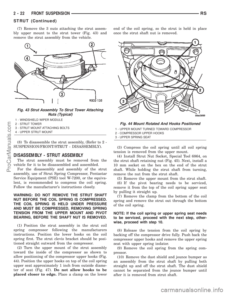
(7) Remove the 3 nuts attaching the strut assem-
bly upper mount to the strut tower (Fig. 43) and
remove the strut assembly from the vehicle.
(8) To disassemble the strut assembly, (Refer to 2 -
SUSPENSION/FRONT/STRUT - DISASSEMBLY).
DISASSEMBLY - STRUT ASSEMBLY
The strut assembly must be removed from the
vehicle for it to be disassembled and assembled.
For the disassembly and assembly of the strut
assembly, use of Strut Spring Compressor, Pentastar
Service Equipment (PSE) tool W-7200, or the equiva-
lent, is recommended to compress the coil spring.
Follow the manufacturer's instructions closely.
WARNING: DO NOT REMOVE THE STRUT SHAFT
NUT BEFORE THE COIL SPRING IS COMPRESSED.
THE COIL SPRING IS HELD UNDER PRESSURE
AND MUST BE COMPRESSED, REMOVING SPRING
TENSION FROM THE UPPER MOUNT AND PIVOT
BEARING, BEFORE THE SHAFT NUT IS REMOVED.
(1) Position the strut assembly in the strut coil
spring compressor following the manufacturers
instructions. Position the lower hooks on the coil
spring first. The strut clevis bracket should be posi-
tioned straight outward from the compressor.
(2) Turn the upper mount of the strut assembly
toward the inside of the compressor as shown to
allow positioning of the compressor upper hooks (Fig.
44). Position the upper hooks on top of the coil spring
upper seat approximately 1 inch from outside diame-
ter of seat (Fig. 47).Do not allow hooks to be
placed closer to edge.Place a clamp on the lowerend of the coil spring, so the strut is held in place
once the strut shaft nut is removed.
(3) Compress the coil spring until all coil spring
tension is removed from the upper mount.
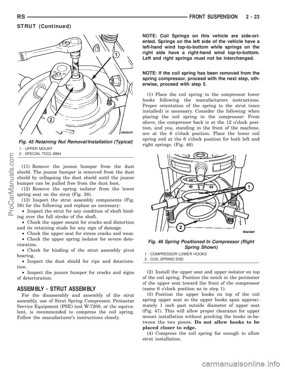
(4) Install Strut Nut Socket, Special Tool 6864, on
the strut shaft retaining nut (Fig. 45). Next, install a
10 mm socket on the hex on the end of the strut
shaft. While holding the strut shaft from turning,
remove the nut from the strut shaft.
(5) Remove the upper mount from the strut shaft.
(6) If the pivot bearing needs to be serviced,
remove it from the top of the coil spring upper seat
by pulling it straight up.
(7) Remove the clamp from the bottom of the coil
spring and remove the strut out through the bottom
of the coil spring.
NOTE: If the coil spring or upper spring seat needs
to be serviced, proceed with the next step, other-
wise, proceed with step 10.
(8) Release the tension from the coil spring by
backing off the compressor drive fully. Push back the
compressor upper hooks and remove the upper spring
seat with upper spring isolator.
(9) Remove the coil spring from the spring com-
pressor.
(10) Remove the dust shield and jounce bumper as
an assembly from the strut shaft by pulling both
straight up and off the strut shaft. The dust shield
cannot be separated from the jounce bumper until
after it is removed from strut shaft.
Fig. 43 Strut Assembly To Strut Tower Attaching
Nuts (Typical)
1 - WINDSHIELD WIPER MODULE
2 - STRUT TOWER
3 - STRUT MOUNT ATTACHING BOLTS
4 - UPPER STRUT MOUNT
Fig. 44 Mount Rotated And Hooks Positioned
1 - UPPER MOUNT TURNED TOWARD COMPRESSOR
2 - COMPRESSOR UPPER HOOKS
3 - UPPER SPRING SEAT
2 - 22 FRONT SUSPENSIONRS
STRUT (Continued)
ProCarManuals.com
Page 46 of 2399
(11) Remove the jounce bumper from the dust
shield. The jounce bumper is removed from the dust
shield by collapsing the dust shield until the jounce
bumper can be pulled free from the dust boot.
(12) Remove the spring isolator from the lower
spring seat on the strut (Fig. 38).
(13) Inspect the strut assembly components (Fig.
38) for the following and replace as necessary:
²Inspect the strut for any condition of shaft bind-
ing over the full stroke of the shaft.
²Check the upper mount for cracks and distortion
and its retaining studs for any sign of damage.
²Check the upper seat for stress cracks and wear.
²Check the upper spring isolator for severe dete-
rioration.
²Check for binding of the strut assembly pivot
bearing.
²Inspect the dust shield for rips and deteriora-
tion.
²Inspect the jounce bumper for cracks and signs
of deterioration.
ASSEMBLY - STRUT ASSEMBLY
For the disassembly and assembly of the strut
assembly, use of Strut Spring Compressor, Pentastar
Service Equipment (PSE) tool W-7200, or the equiva-
lent, is recommended to compress the coil spring.
Follow the manufacturer's instructions closely.NOTE: Coil Springs on this vehicle are side-ori-
ented. Springs on the left side of the vehicle have a
left-hand wind top-to-bottom while springs on the
right side have a right-hand wind top-to-bottom.
Left and right springs must not be interchanged.
NOTE: If the coil spring has been removed from the
spring compressor, proceed with the next step, oth-
erwise, proceed with step 5.
(1) Place the coil spring in the compressor lower
hooks following the manufacturers instructions.
Proper orientation of the spring to the strut (once
installed) is necessary. Consider the following when
placing the coil spring in the compressor: From
above, the compressor back is at the 12 o'clock posi-
tion, and you, standing in the front of the machine,
are at the 6 o'clock position. Place the lower coil
spring end at the 6 o'clock position for both left and
right springs. (Fig. 46).
(2) Install the upper seat and upper isolator on top
of the coil spring. Position the notch in the perimeter
of the upper seat toward the front of the compressor
(same 6 o'clock position as in step 1).
(3) Position the upper hooks on top of the coil
spring upper seat so the upper hooks span approxi-
mately 1 inch past outside diameter of upper seat
(Fig. 47). This will allow proper clearance for upper
mount installation without pinching the hooks in-be-
tween the two pieces.Do not allow hooks to be
placed closer to edge.
(4) Compress the coil spring far enough to allow
strut installation.
Fig. 45 Retaining Nut Removal/Installation (Typical)
1 - UPPER MOUNT
2 - SPECIAL TOOL 6864
Fig. 46 Spring Positioned In Compressor (Right
Spring Shown)
1 - COMPRESSOR LOWER HOOKS
2 - COIL SPRING END
RSFRONT SUSPENSION2-23
STRUT (Continued)
ProCarManuals.com
Page 69 of 2399
WHEEL ALIGNMENT
TABLE OF CONTENTS
page page
WHEEL ALIGNMENT
DESCRIPTION - WHEEL ALIGNMENT.......46
DIAGNOSIS AND TESTING - SUSPENSION
AND STEERING......................49
STANDARD PROCEDURE
STANDARD PROCEDURE - WHEEL
ALIGNMENT.........................51STANDARD PROCEDURE - CURB HEIGHT
MEASUREMENT......................54
STANDARD PROCEDURE - CURB HEIGHT
MEASUREMENT (EXPORT)..............55
SPECIFICATIONS
WHEEL ALIGNMENT...................56
WHEEL ALIGNMENT
DESCRIPTION - WHEEL ALIGNMENT
Vehicle wheel alignment is the positioning of all
interrelated front and rear suspension angles. These
angles affect the handling and steering of the vehicle
when it is in motion. Proper wheel alignment is
essential for efficient steering, good directional stabil-
ity, and proper tire wear.
The method of checking a vehicle's front and rear
wheel alignment varies depending on the manufac-
turer and type of equipment used. The manufactur-
er's instructions should always be followed to ensure
accuracy of the alignment, except when
DaimlerChrysler Corporation's wheel alignment spec-
ifications differ.
On this vehicle, the suspension angles that can be
adjusted are as follows:
²Front Camber (with camber bolt package and
standard procedure)
²Front Toe
Check the wheel alignment and make all wheel
alignment adjustments with the vehicle standing at
its proper curb height specification. Curb height is
the normal riding height of the vehicle. It is mea-
sured from a certain point on the vehicle to the
ground or a designated area while the vehicle is sit-
ting on a flat, level surface. Refer to Curb Height
Measurement in this section for additional informa-
tion.
Typical wheel alignment angles and measurements
are described in the following paragraphs.
CAMBER
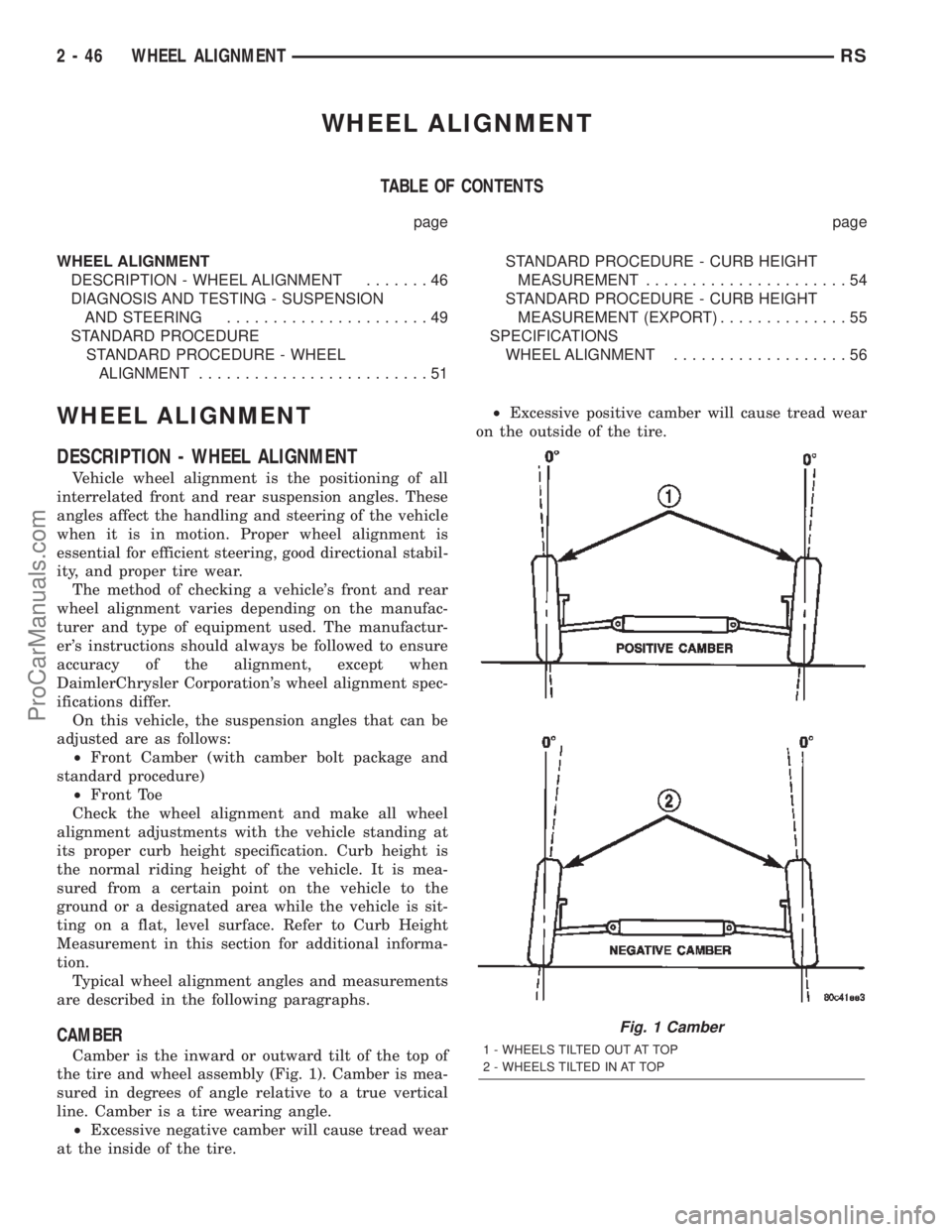
Camber is the inward or outward tilt of the top of
the tire and wheel assembly (Fig. 1). Camber is mea-
sured in degrees of angle relative to a true vertical
line. Camber is a tire wearing angle.
²Excessive negative camber will cause tread wear
at the inside of the tire.²Excessive positive camber will cause tread wear
on the outside of the tire.
Fig. 1 Camber
1 - WHEELS TILTED OUT AT TOP
2 - WHEELS TILTED IN AT TOP
2 - 46 WHEEL ALIGNMENTRS
ProCarManuals.com
Page 74 of 2399
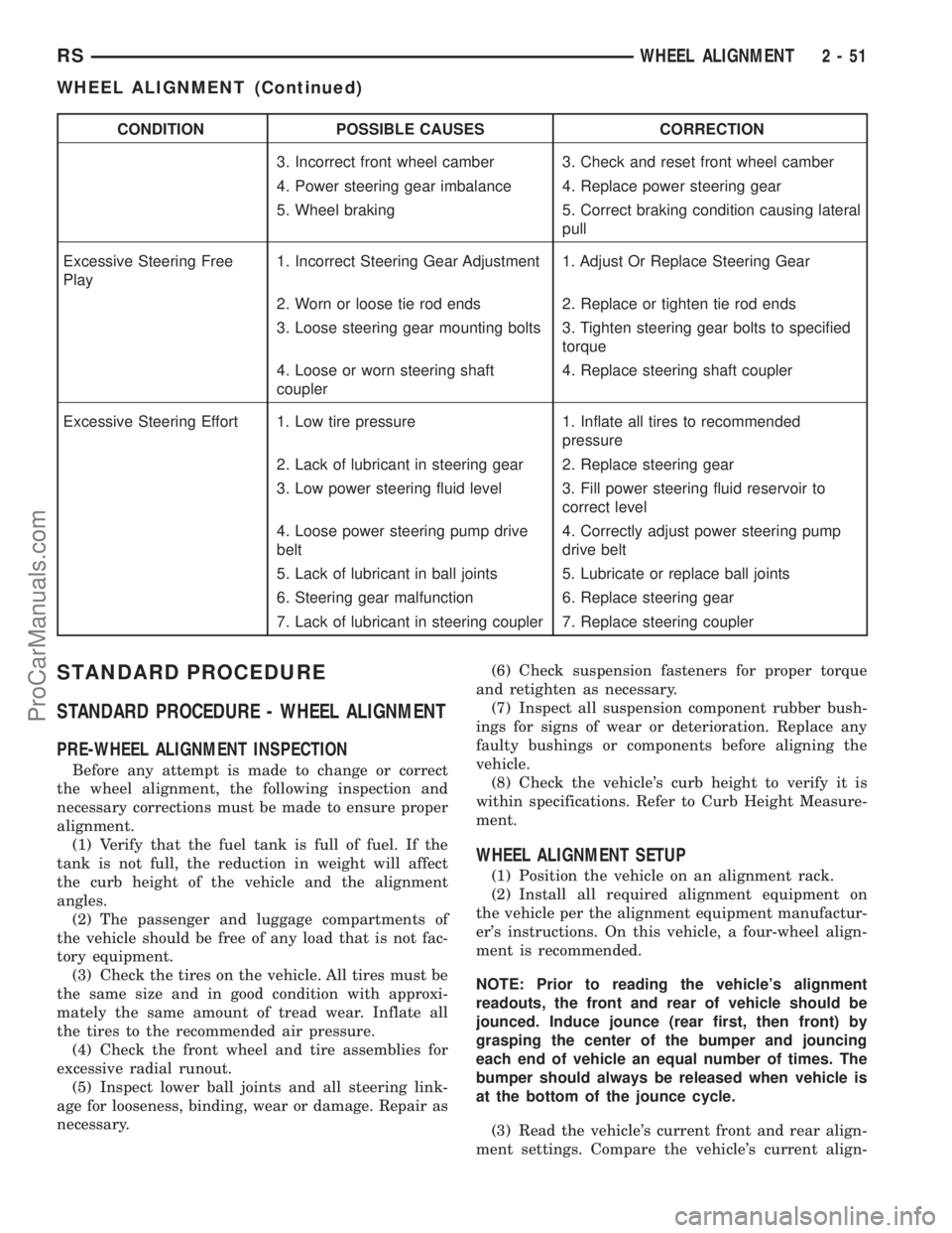
CONDITION POSSIBLE CAUSES CORRECTION
3. Incorrect front wheel camber 3. Check and reset front wheel camber
4. Power steering gear imbalance 4. Replace power steering gear
5. Wheel braking 5. Correct braking condition causing lateral
pull
Excessive Steering Free
Play1. Incorrect Steering Gear Adjustment 1. Adjust Or Replace Steering Gear
2. Worn or loose tie rod ends 2. Replace or tighten tie rod ends
3. Loose steering gear mounting bolts 3. Tighten steering gear bolts to specified
torque
4. Loose or worn steering shaft
coupler4. Replace steering shaft coupler
Excessive Steering Effort 1. Low tire pressure 1. Inflate all tires to recommended
pressure
2. Lack of lubricant in steering gear 2. Replace steering gear
3. Low power steering fluid level 3. Fill power steering fluid reservoir to
correct level
4. Loose power steering pump drive
belt4. Correctly adjust power steering pump
drive belt
5. Lack of lubricant in ball joints 5. Lubricate or replace ball joints
6. Steering gear malfunction 6. Replace steering gear
7. Lack of lubricant in steering coupler 7. Replace steering coupler
STANDARD PROCEDURE
STANDARD PROCEDURE - WHEEL ALIGNMENT
PRE-WHEEL ALIGNMENT INSPECTION
Before any attempt is made to change or correct
the wheel alignment, the following inspection and
necessary corrections must be made to ensure proper
alignment.
(1) Verify that the fuel tank is full of fuel. If the
tank is not full, the reduction in weight will affect
the curb height of the vehicle and the alignment
angles.
(2) The passenger and luggage compartments of
the vehicle should be free of any load that is not fac-
tory equipment.
(3) Check the tires on the vehicle. All tires must be
the same size and in good condition with approxi-
mately the same amount of tread wear. Inflate all
the tires to the recommended air pressure.
(4) Check the front wheel and tire assemblies for
excessive radial runout.
(5) Inspect lower ball joints and all steering link-
age for looseness, binding, wear or damage. Repair as
necessary.(6) Check suspension fasteners for proper torque
and retighten as necessary.
(7) Inspect all suspension component rubber bush-
ings for signs of wear or deterioration. Replace any
faulty bushings or components before aligning the
vehicle.
(8) Check the vehicle's curb height to verify it is
within specifications. Refer to Curb Height Measure-
ment.
WHEEL ALIGNMENT SETUP
(1) Position the vehicle on an alignment rack.
(2) Install all required alignment equipment on
the vehicle per the alignment equipment manufactur-
er's instructions. On this vehicle, a four-wheel align-
ment is recommended.
NOTE: Prior to reading the vehicle's alignment
readouts, the front and rear of vehicle should be
jounced. Induce jounce (rear first, then front) by
grasping the center of the bumper and jouncing
each end of vehicle an equal number of times. The
bumper should always be released when vehicle is
at the bottom of the jounce cycle.
(3) Read the vehicle's current front and rear align-
ment settings. Compare the vehicle's current align-
RSWHEEL ALIGNMENT2-51
WHEEL ALIGNMENT (Continued)
ProCarManuals.com
Page 77 of 2399
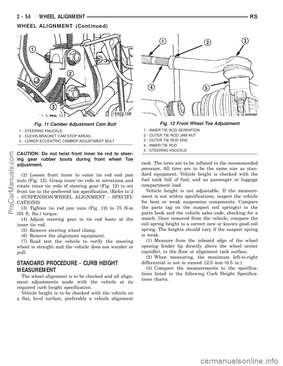
CAUTION: Do not twist front inner tie rod to steer-
ing gear rubber boots during front wheel Toe
adjustment.
(2) Loosen front inner to outer tie rod end jam
nuts (Fig. 12). Grasp inner tie rods at serrations and
rotate inner tie rods of steering gear (Fig. 12) to set
front toe to the preferred toe specification. (Refer to 2
- SUSPENSION/WHEEL ALIGNMENT - SPECIFI-
CATIONS)
(3) Tighten tie rod jam nuts (Fig. 12) to 75 N´m
(55 ft. lbs.) torque.
(4) Adjust steering gear to tie rod boots at the
inner tie rod.
(5) Remove steering wheel clamp.
(6) Remove the alignment equipment.
(7) Road test the vehicle to verify the steering
wheel is straight and the vehicle does not wander or
pull.
STANDARD PROCEDURE - CURB HEIGHT
MEASUREMENT
The wheel alignment is to be checked and all align-
ment adjustments made with the vehicle at its
required curb height specification.
Vehicle height is to be checked with the vehicle on
a flat, level surface, preferably a vehicle alignmentrack. The tires are to be inflated to the recommended
pressure. All tires are to be the same size as stan-
dard equipment. Vehicle height is checked with the
fuel tank full of fuel, and no passenger or luggage
compartment load.
Vehicle height is not adjustable. If the measure-
ment is not within specifications, inspect the vehicle
for bent or weak suspension components. Compare
the parts tag on the suspect coil spring(s) to the
parts book and the vehicle sales code, checking for a
match. Once removed from the vehicle, compare the
coil spring height to a correct new or known good coil
spring. The heights should vary if the suspect spring
is weak.
(1) Measure from the inboard edge of the wheel
opening fender lip directly above the wheel center
(spindle), to the floor or alignment rack surface.
(2) When measuring, the maximum left-to-right
differential is not to exceed 12.5 mm (0.5 in.).
(3) Compare the measurements to the specifica-
tions listed in the following Curb Height Specifica-
tions charts.
Fig. 11 Camber Adjustment Cam Bolt
1 - STEERING KNUCKLE
2 - CLEVIS BRACKET CAM STOP AREAS
3 - LOWER ECCENTRIC CAMBER ADJUSTMENT BOLT
Fig. 12 Front Wheel Toe Adjustment
1 - INNER TIE ROD SERRATION
2 - OUTER TIE ROD JAM NUT
3 - OUTER TIE ROD END
4 - INNER TIE ROD
5 - STEERING KNUCKLE
2 - 54 WHEEL ALIGNMENTRS
WHEEL ALIGNMENT (Continued)
ProCarManuals.com
Page 78 of 2399
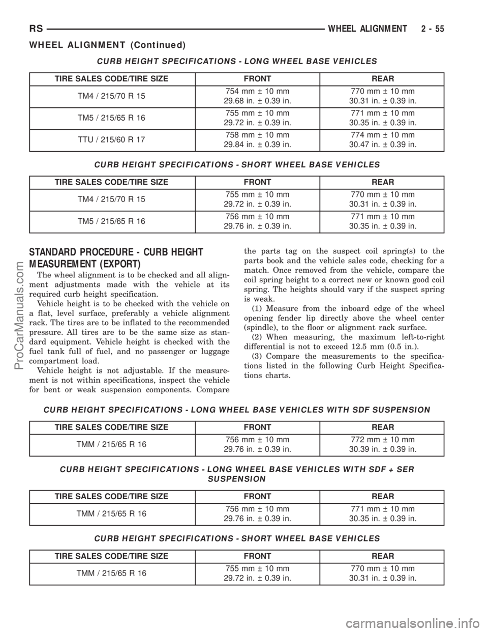
CURB HEIGHT SPECIFICATIONS - LONG WHEEL BASE VEHICLES
TIRE SALES CODE/TIRE SIZE FRONT REAR
TM4 / 215/70 R 15754mm 10mm
29.68 in. 0.39 in.770mm 10mm
30.31 in. 0.39 in.
TM5 / 215/65 R 16755mm 10mm
29.72 in. 0.39 in.771mm 10mm
30.35 in. 0.39 in.
TTU / 215/60 R 17758mm 10mm
29.84 in. 0.39 in.774mm 10mm
30.47 in. 0.39 in.
CURB HEIGHT SPECIFICATIONS - SHORT WHEEL BASE VEHICLES
TIRE SALES CODE/TIRE SIZE FRONT REAR
TM4 / 215/70 R 15755mm 10mm
29.72 in. 0.39 in.770mm 10mm
30.31 in. 0.39 in.
TM5 / 215/65 R 16756mm 10mm
29.76 in. 0.39 in.771mm 10mm
30.35 in. 0.39 in.
STANDARD PROCEDURE - CURB HEIGHT
MEASUREMENT (EXPORT)
The wheel alignment is to be checked and all align-
ment adjustments made with the vehicle at its
required curb height specification.
Vehicle height is to be checked with the vehicle on
a flat, level surface, preferably a vehicle alignment
rack. The tires are to be inflated to the recommended
pressure. All tires are to be the same size as stan-
dard equipment. Vehicle height is checked with the
fuel tank full of fuel, and no passenger or luggage
compartment load.
Vehicle height is not adjustable. If the measure-
ment is not within specifications, inspect the vehicle
for bent or weak suspension components. Comparethe parts tag on the suspect coil spring(s) to the
parts book and the vehicle sales code, checking for a
match. Once removed from the vehicle, compare the
coil spring height to a correct new or known good coil
spring. The heights should vary if the suspect spring
is weak.
(1) Measure from the inboard edge of the wheel
opening fender lip directly above the wheel center
(spindle), to the floor or alignment rack surface.
(2) When measuring, the maximum left-to-right
differential is not to exceed 12.5 mm (0.5 in.).
(3) Compare the measurements to the specifica-
tions listed in the following Curb Height Specifica-
tions charts.
CURB HEIGHT SPECIFICATIONS - LONG WHEEL BASE VEHICLES WITH SDF SUSPENSION
TIRE SALES CODE/TIRE SIZE FRONT REAR
TMM / 215/65 R 16756mm 10mm
29.76 in. 0.39 in.772mm 10mm
30.39 in. 0.39 in.
CURB HEIGHT SPECIFICATIONS - LONG WHEEL BASE VEHICLES WITH SDF + SER
SUSPENSION
TIRE SALES CODE/TIRE SIZE FRONT REAR
TMM / 215/65 R 16756mm 10mm
29.76 in. 0.39 in.771mm 10mm
30.35 in. 0.39 in.
CURB HEIGHT SPECIFICATIONS - SHORT WHEEL BASE VEHICLES
TIRE SALES CODE/TIRE SIZE FRONT REAR
TMM / 215/65 R 16755mm 10mm
29.72 in. 0.39 in.770mm 10mm
30.31 in. 0.39 in.
RSWHEEL ALIGNMENT2-55
WHEEL ALIGNMENT (Continued)
ProCarManuals.com
Page 133 of 2399
come in contact with a hub mounted drum (drum for
disc/drum brakes or drum-in-hat for disc/disc brakes)
and hold it in place.
WARNING
WARNING: DUST AND DIRT ACCUMULATING ON
BRAKE PARTS DURING NORMAL USE MAY CON-
TAIN ASBESTOS FIBERS FROM PRODUCTION OR
AFTERMARKET BRAKE LININGS. BREATHING
EXCESSIVE CONCENTRATIONS OF ASBESTOS
FIBERS CAN CAUSE SERIOUS BODILY HARM.
EXERCISE CARE WHEN SERVICING BRAKE
PARTS. DO NOT SAND OR GRIND BRAKE LINING
UNLESS EQUIPMENT USED IS DESIGNED TO CON-
TAIN THE DUST RESIDUE. DO NOT CLEAN BRAKE
PARTS WITH COMPRESSED AIR OR BY DRY
BRUSHING. CLEANING SHOULD BE DONE BY
DAMPENING THE BRAKE COMPONENTS WITH A
FINE MIST OF WATER, THEN WIPING THE BRAKE
COMPONENTS CLEAN WITH A DAMPENED CLOTH.
DISPOSE OF CLOTH AND ALL RESIDUE CONTAIN-
ING ASBESTOS FIBERS IN AN IMPERMEABLE
CONTAINER WITH THE APPROPRIATE LABEL. FOL-
LOW PRACTICES PRESCRIBED BY THE OCCUPA-
TIONAL SAFETY AND HEALTH ADMINISTRATION
(OSHA) AND THE ENVIRONMENTAL PROTECTION
AGENCY (EPA) FOR THE HANDLING, PROCESSING,
AND DISPOSING OF DUST OR DEBRIS THAT MAY
CONTAIN ASBESTOS FIBERS.
CAUTION
CAUTION: During service procedures, grease or
any other foreign material must be kept off brake
shoe assemblies, and braking surfaces of brake
rotor or drum, and external surfaces of hub and
bearing assembly.
CAUTION: Handling of brake rotors and calipers
must be done in such a way as to avoid damage to
the rotor and scratching or nicking of brake lining
on the brake shoes.
CAUTION: At no time when servicing a vehicle, can
a sheet metal screw, bolt or other metal fastener be
installed in the shock tower to take the place of an
original plastic clip. Also, NO holes can be drilled
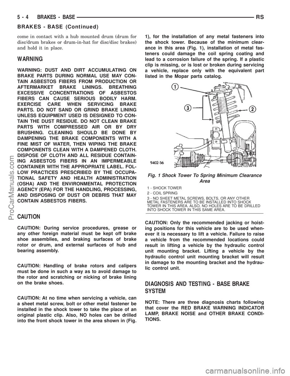
into the front shock tower in the area shown in (Fig.1), for the installation of any metal fasteners into
the shock tower. Because of the minimum clear-
ance in this area (Fig. 1), installation of metal fas-
teners could damage the coil spring coating and
lead to a corrosion failure of the spring. If a plastic
clip is missing, or is lost or broken during servicing
a vehicle, replace only with the equivalent part
listed in the Mopar parts catalog.
CAUTION: Only the recommended jacking or hoist-
ing positions for this vehicle are to be used when-
ever it is necessary to lift a vehicle. Failure to raise
a vehicle from the recommended locations could
result in lifting a vehicle by the hydraulic control
unit mounting bracket. Lifting a vehicle by the
hydraulic control unit mounting bracket will result
in damage to the mounting bracket and the hydrau-
lic control unit.
DIAGNOSIS AND TESTING - BASE BRAKE
SYSTEM
NOTE: There are three diagnosis charts following
that cover the RED BRAKE WARNING INDICATOR
LAMP, BRAKE NOISE and OTHER BRAKE CONDI-
TIONS.
Fig. 1 Shock Tower To Spring Minimum Clearance
Area
1 - SHOCK TOWER
2 - COIL SPRING
3 - NO SHEET METAL SCREWS, BOLTS, OR ANY OTHER
METAL FASTENERS ARE TO BE INSTALLED INTO SHOCK
TOWER IN THIS AREA. ALSO, NO HOLES ARE TO BE DRILLED
INTO SHOCK TOWER IN THIS SAME AREA.
5 - 4 BRAKES - BASERS
BRAKES - BASE (Continued)
ProCarManuals.com