speed CHRYSLER VOYAGER 2002 Service Manual
[x] Cancel search | Manufacturer: CHRYSLER, Model Year: 2002, Model line: VOYAGER, Model: CHRYSLER VOYAGER 2002Pages: 2399, PDF Size: 57.96 MB
Page 1 of 2399
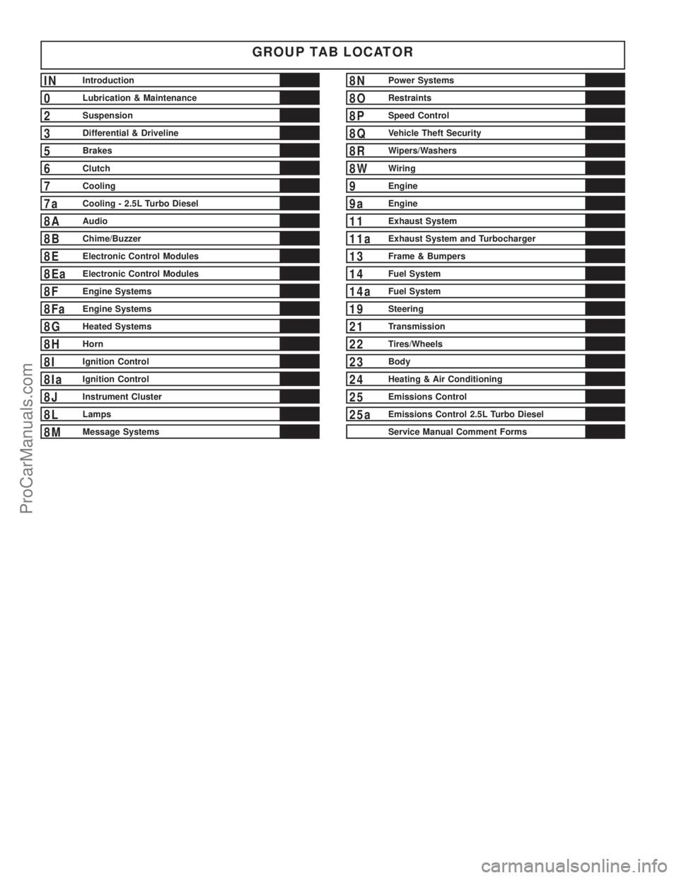
GROUP TAB LOCATOR
INIntroduction
0Lubrication & Maintenance
2Suspension
3Differential & Driveline
5Brakes
6Clutch
7Cooling
7aCooling - 2.5L Turbo Diesel
8AAudio
8BChime/Buzzer
8EElectronic Control Modules
8EaElectronic Control Modules
8FEngine Systems
8FaEngine Systems
8GHeated Systems
8HHorn
8IIgnition Control
8IaIgnition Control
8JInstrument Cluster
8LLamps
8MMessage Systems
8NPower Systems
8ORestraints
8PSpeed Control
8QVehicle Theft Security
8RWipers/Washers
8WWiring
9Engine
9aEngine
11Exhaust System
11aExhaust System and Turbocharger
13Frame & Bumpers
14Fuel System
14aFuel System
19Steering
21Transmission
22Tires/Wheels
23Body
24Heating & Air Conditioning
25Emissions Control
25aEmissions Control 2.5L Turbo Diesel
Service Manual Comment Forms
ProCarManuals.com
Page 3 of 2399
DIGIT 21
Price Class
²H = Highline
²L = Lowline
²P = Premium
²S = Luxury
²X = Premium
DIGITS 22 AND 23
Body Type
²52 = Short Wheel Base
²53 = Long Wheel Base
BODY CODE PLATE LINE 2
DIGITS 1, 2 AND 3
Paint Procedure
DIGIT 4
Open Space
DIGITS 5 THROUGH 7
Primary Paint (Refer to 23 - BODY/PAINT - SPEC-
IFICATIONS).
DIGIT 8 AND 9
Open Space
DIGITS 10 THROUGH 12
Secondary Paint
DIGIT 13 AND 14
Open Space
DIGITS 15 THROUGH 18
Interior Trim Code
DIGIT 19
Open Space
DIGITS 20, 21, AND 22
Engine Code
²EDZ = 2.4L 4 cyl. 16-Valve DOHC Gasoline
(MPI)
²EGA = 3.3L 6 cyl. Gasoline (SMPI)
²EGH = 3.8L 6 cyl. Gasoline (SMPI)
²EGM = 3.3L 6 cyl. Ethanol Flexible Fuel
²ENJ = 2.5L 4 cyl. 16-Valve Turbo Diesel
DIGIT 23
Open Space
BODY CODE PLATE LINE 1
DIGITS 1, 2, AND 3
Transaxle Codes
²DGC = 31TH 3-Speed Automatic Transaxle
²DGL = 41AE/TE 4-Speed Electronic Automatic
²DDR = T850 5-Speed Manual Transaxle
DIGIT 4
Open Space
DIGIT 5
Market Code
²C = Canada
²B = International
²M = Mexico
²U = United States
DIGIT 6
Open Space
DIGITS 7 THROUGH 23
Vehicle Identification Number
²Refer to Vehicle Identification Number (VIN)
paragraph for proper breakdown of VIN code.
IF TWO BODY CODE PLATES ARE REQUIRED
The last code shown on either plate will be fol-
lowed by END. When two plates are required, the
last code space on the first plate will indicate (CTD)
When a second plate is required, the first four
spaces of each line will not be used due to overlap of
the plates.
FASTENER IDENTIFICATION
DESCRIPTION
The SAE bolt strength grades range from grade 2
to grade 8. The higher the grade number, the greater
the bolt strength. Identification is determined by the
line marks on the top of each bolt head. The actual
bolt strength grade corresponds to the number of line
marks plus 2. The most commonly used metric bolt
strength classes are 9.8 and 10.9. The metric
strength class identification number is imprinted on
the head of the bolt. The higher the class number,
the greater the bolt strength. Some metric nuts are
imprinted with a single-digit strength class on the
nut face. Refer to the Fastener Identification and
Fastener Strength Charts (Fig. 2) and (Fig. 3).
2 INTRODUCTIONRS
BODY CODE PLATE (Continued)
ProCarManuals.com
Page 11 of 2399

POSITION INTERPRETATION CODE = DESCRIPTION
6 Series 2 = Low Line
4 = High Line
5 = Premium
6 = Sport
7 = Special
6 - Export Series B = 4-Speed Automatic Transaxle
N = 5-Speed Manual Transaxle
7 Body Style 4 = Long Wheel Base
5 = Short Wheel Base
7 - Export Body Style 1 = EURO Wagon-Long Wheelbase RG-53-S Series
2 = EURO Wagon-Short Wheelbase RG-52-H Series
3 = EURO Wagon-Short Wheelbase RG-52-P Series
4 = EURO Wagon-Long Wheelbase RG-53-P Series
5 = EURO Wagon-Long Wheelbase RG-53-H Series
6 = Comercial Van-Short Wheelbase with-CYX Less AS8
7 = Comercial Van-Short Wheelbase with AS8
8 = Comercial Van-Long Wheelbase Highline with-CYX
9 = Comercial Van-Long Wheelbase Premium Line
with-CYX
CYX = No Rear Seat Package
AS8 = Interior Delete Group
8 Engine B = 2.4L 4 cyl. 16-Valve Gasoline DOHC (MPI)
L = 3.8L 6 cyl. Gasoline (SMPI)
R = 3.3L 6 cyl. Gasoline (SMPI)
3 = 3.3L 6 cyl. Enthanol Flex Fuel
7 = 2.5L 4 cyl. 16 Valve Turbo Diesel
9 Check Digit See explanation in this section.
10 Model Year 2= 2002
11 Assembly Plant B = St. Louis Assembly South
R = Windsor Assembly
U = Graz Assembly
12 through 17 Sequence Number A six digit number assigned by assembly plant.
10 INTRODUCTIONRS
VEHICLE IDENTIFICATION NUMBER (Continued)
ProCarManuals.com
Page 14 of 2399

LUBRICATION & MAINTENANCE
TABLE OF CONTENTS
page page
LUBRICATION & MAINTENANCE
SPECIFICATIONS - FLUID CAPACITIES.......1
INTERNATIONAL SYMBOLS
DESCRIPTION..........................2
FLUID TYPES
DESCRIPTION
DESCRIPTION - ENGINE OIL AND
LUBRICANTS.........................2
DESCRIPTION - ENGINE COOLANT........3
DESCRIPTION - FLEXIBLE FUEL ENGINE
OIL .................................3
DESCRIPTION - AUTOMATIC
TRANSMISSION FLUID..................4
DESCRIPTION - FUEL REQUIREMENTS.....4
DESCRIPTION - FUEL REQUIREMENTS -
DIESEL ENGINE.......................6DESCRIPTION - ENGINE OIL - DIESEL
ENGINES............................6
FLUID FILL/CHECK LOCATIONS
DESCRIPTION..........................6
LUBRICATION POINTS
DESCRIPTION..........................6
MAINTENANCE SCHEDULES
DESCRIPTION..........................6
HOISTING
STANDARD PROCEDURE - HOISTING........6
JUMP STARTING
STANDARD PROCEDURE - JUMP STARTING . . 7
TOWING
STANDARD PROCEDURE - TOWING.........8
LUBRICATION &
MAINTENANCE
SPECIFICATIONS - FLUID CAPACITIES
DESCRIPTION SPECIFICATION
Fuel Tank (Gas) 75 L (20 gal.)
Fuel Tank (Diesel) 75 L (20 gal.)
Engine Oil* - 2.4 L 4.7 L (5.0 qts.)
Engine Oil* - 3.3/3.8 L 4.0 L (4.5 qts.)
Engine Oil* - 2.5 L
(Diesel)6.0 L (6.3 qts.)
Cooling System** - 2.4 L 10.7 L (11.4 qts.)
Cooling System** - 2.5 L
Turbo Diesel with
Auxiliary Heater13.8 L (14.6 qts.)
Cooling System** -
3.3/3.8 L without Auxiliary
Heater12.6 L (13.4 qts.)
DESCRIPTION SPECIFICATION
Cooling System** -
3.3/3.8 L with Auxiliary
Heater15.4 L (16.3 qts.)
Automatic Transaxle -
Service Fill3.8 L (4.0 qts.)
Automatic Transaxle -
31TH Overhaul Fill8.6 L (9.1 qts.)
Automatic Transaxle -
41TE Overhaul Fill9.2 L (9.7 qts.)
Manual Transaxle (T850
5-Speed)2.4-2.7 L (2.5-2.9 qts.)
AWD Power Transfer Unit 1.15 L (2.4 pts.)
Power Steering 1.2 L (2.5 pts.)
AWD Bi-directional
Overrunning Clutch0.575 L (1.22 pts.)
AWD Rear Carrier 0.7 L (1.48 pts.)
* (includes oil filter)
** (includes heater and recovery/reserve bottle)
RSLUBRICATION & MAINTENANCE0-1
ProCarManuals.com
Page 18 of 2399
Light spark knock at low engine speeds is not
harmful to your engine. However, continued heavy
spark knock at high speeds can cause damage and
immediate service is required. Engine damage result-
ing from operation with a heavy spark knock may
not be covered by the new vehicle warranty.
Poor quality gasoline can cause problems such as
hard starting, stalling and hesitations. If you experi-
ence these symptoms, try another brand of gasoline
before considering service for the vehicle.
Over 40 auto manufacturers world-wide have
issued and endorsed consistent gasoline specifications
(the Worldwide Fuel Charter, WWFC) to define fuel
properties necessary to deliver enhanced emissions,
performance and durability for your vehicle. We rec-
ommend the use of gasolines that meet the WWFC
specifications if they are available.
REFORMULATED GASOLINE
Many areas of the country require the use of
cleaner burning gasoline referred to as ªreformulat-
edº gasoline. Reformulated gasoline contain oxygen-
ates, and are specifically blended to reduce vehicle
emissions and improve air quality.
We strongly support the use of reformulated gaso-
line. Properly blended reformulated gasoline will pro-
vide excellent performance and durability for the
engine and fuel system components.
GASOLINE/OXYGENATE BLENDS
Some fuel suppliers blend unleaded gasoline with
oxygenates such as 10% ethanol, MTBE, and ETBE.
Oxygenates are required in some areas of the country
during the winter months to reduce carbon monoxide
emissions. Fuels blended with these oxygenates may
be used in your vehicle.
CAUTION: DO NOT use gasoline containing METH-
ANOL. Gasoline containing methanol may damage
critical fuel system components.
MMT IN GASOLINE
MMT is a manganese-containing metallic additive
that is blended into some gasoline to increase octane.
Gasoline blended with MMT provide no performance
advantage beyond gasoline of the same octane num-
ber without MMT. Gasoline blended with MMT
reduce spark plug life and reduce emission system
performance in some vehicles. We recommend that
gasoline free of MMT be used in your vehicle. The
MMT content of gasoline may not be indicated on the
gasoline pump; therefore, you should ask your gaso-
line retailer whether or not his/her gasoline contains
MMT.
It is even more important to look for gasoline with-
out MMT in Canada because MMT can be used atlevels higher than allowed in the United States.
MMT is prohibited in Federal and California refor-
mulated gasoline.
SULFUR IN GASOLINE
If you live in the northeast United States, your
vehicle may have been designed to meet California
low emission standards with Cleaner-Burning Cali-
fornia reformulated gasoline with low sulfur. If such
fuels are not available in states adopting California
emission standards, your vehicles will operate satis-
factorily on fuels meeting federal specifications, but
emission control system performance may be
adversely affected. Gasoline sold outside of California
is permitted to have higher sulfur levels which may
affect the performance of the vehicle's catalytic con-
verter. This may cause the Malfunction Indicator
Lamp (MIL), Check Engine or Service Engine Soon
light to illuminate. We recommend that you try a dif-
ferent brand of unleaded gasoline having lower sulfur
to determine if the problem is fuel related prior to
returning your vehicle to an authorized dealer for
service.
CAUTION: If the Malfunction Indicator Lamp (MIL),
Check Engine or Service Engine Soon light is flash-
ing, immediate service is required; see on-board
diagnostics system section.
MATERIALS ADDED TO FUEL
All gasoline sold in the United States and Canada
are required to contain effective detergent additives.
Use of additional detergents or other additives is not
needed under normal conditions.
FUEL SYSTEM CAUTIONS
CAUTION: Follow these guidelines to maintain your
vehicle's performance:
²The use of leaded gas is prohibited by Federal
law. Using leaded gasoline can impair engine perfor-
mance, damage the emission control system, and
could result in loss of warranty coverage.
²An out-of-tune engine, or certain fuel or ignition
malfunctions, can cause the catalytic converter to
overheat. If you notice a pungent burning odor or
some light smoke, your engine may be out of tune or
malfunctioning and may require immediate service.
Contact your dealer for service assistance.
²When pulling a heavy load or driving a fully
loaded vehicle when the humidity is low and the tem-
perature is high, use a premium unleaded fuel to
help prevent spark knock. If spark knock persists,
lighten the load, or engine piston damage may result.
RSLUBRICATION & MAINTENANCE0-5
FLUID TYPES (Continued)
ProCarManuals.com
Page 22 of 2399
GROUND CLEARANCE
CAUTION: If vehicle is towed with wheels removed,
install lug nuts to retain brake drums or rotors.
A towed vehicle should be raised until the lifted
wheels are a minimum 100 mm (4 in.) from the
ground. Be sure there is at least 100 mm (4 in.)
clearance between the tail pipe and the ground. If
necessary, remove the wheels from the front end of
the vehicle and lower the front end closer to the
ground, to increase the ground clearance at the rear
of the vehicle. Install lug nuts on wheel attaching
studs to retain brake drums or rotors.
LOCKED VEHICLE TOWING
When a locked vehicle must be towed with the
front wheels on the ground, use a towing dolly or flat
bed hauler.
FLAT TOWING WITH TOW BAR
²Three speed automatic transaxle vehicles can be
flat towed at speeds not to exceed 40 km/h (25 mph)
for not more than 25 km (15 miles). The steering col-
umn must be unlocked and gear selector in neutral.
²Four speed electronic automatic transaxle vehi-
cles can be flat towed at speeds not to exceed 72
km/h (44 mph) for not more than 160 km (100 miles).
The steering column must be unlocked and gear
selector in neutral.
²AWD models should not be flat towed. For addi-
tional information, refer toRECOMMENDED TOW-
ING EQUIPMENTin this section.
FLAT BED TOWING TIE DOWNS
CAUTION: Do not tie vehicle down by attaching
chains or cables to suspension components or
engine mounts, damage to vehicle can result.
The vehicle can be tied to a flat bed device using
the two pair of front slots on the bottom surface of
the rails, behind the front wheels. The two pair of
rear slots on the bottom of the rail between the
bumper extension bolts and on the bottom of the rail
just rearward of the jounce bumper. Vehicles
equipped with a rear sway bar have brackets at this
location.
TOWING ± FRONT WHEEL LIFT
If the vehicle is being towed from the front, when-
ever possible ensure at least 10 inches road clearance
to the tires.
TOWING ± REAR WHEEL LIFT
If a vehicle cannot be towed with the front wheels
lifted, the rear wheels can be lifted provided the fol-
lowing guide lines are observed.
CAUTION: Do not use steering column lock to
secure steering wheel during towing operation.
²On AWD vehicles, all four wheels must be free to
rotate. Use towing dollies at unlifted end of vehicle.
²Unlock steering column and secure steering
wheel in straight ahead position with a clamp device
designed for towing.
²Three speed automatic transaxle vehicles can be
flat towed at speeds not to exceed 40 km/h (25 mph)
for not more than 25 km (15 miles). The steering col-
umn must be unlocked and gear selector in neutral.
²Four speed electronic automatic transaxle vehi-
cles can be flat towed at speeds not to exceed 72
km/h (44 mph) for not more than 160 km (100 miles).
The steering column must be unlocked and gear
selector in neutral.
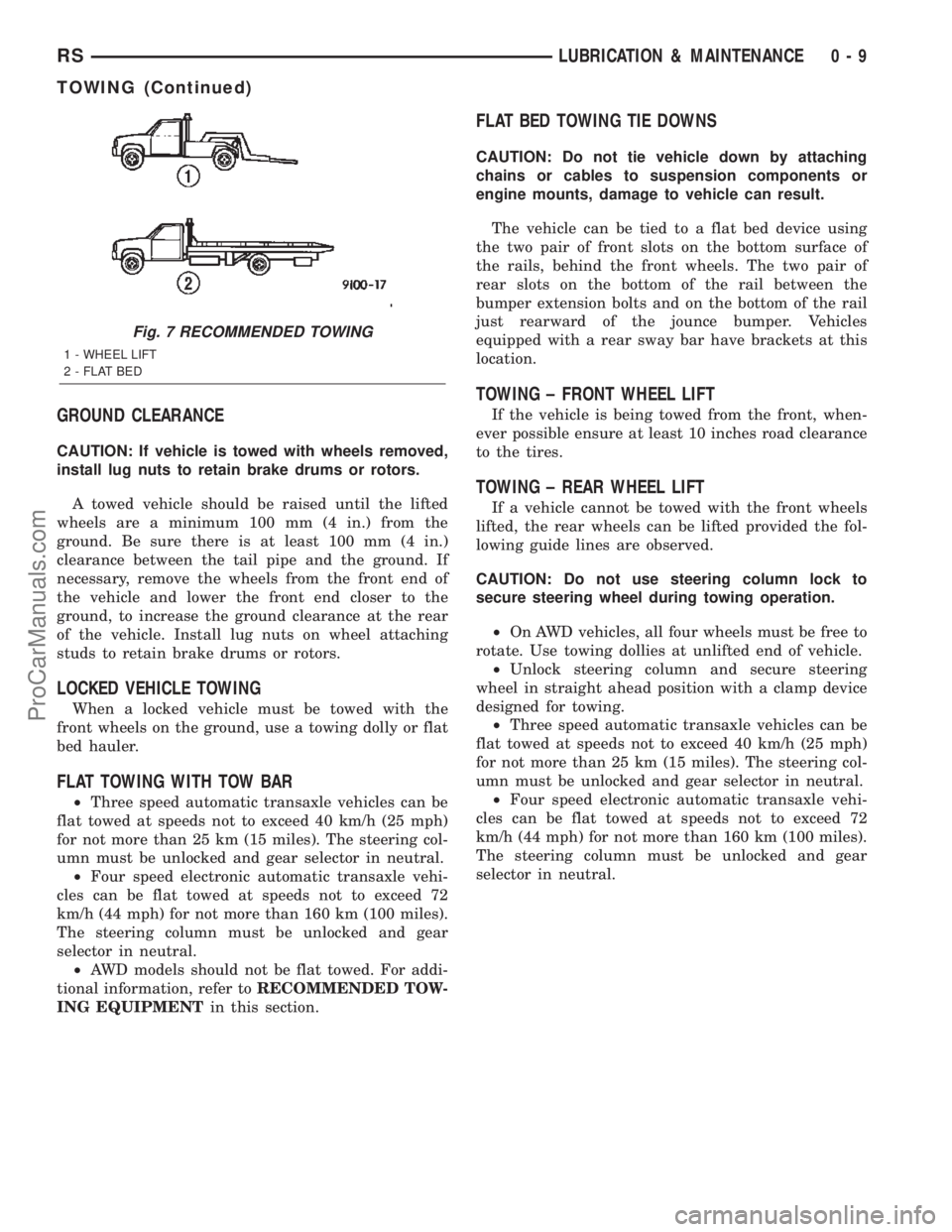
Fig. 7 RECOMMENDED TOWING
1 - WHEEL LIFT
2 - FLAT BED
RSLUBRICATION & MAINTENANCE0-9
TOWING (Continued)
ProCarManuals.com
Page 28 of 2399
DIAGNOSIS AND TESTING - HUB AND
BEARING
The condition of the front hub and bearing assem-
bly is diagnosed using the inspection and testing pro-
cedure detailed below.
The bearing contained in the Unit III front hub/
bearing assembly will produce noise and vibration
when worn or damaged. The noise will generally
change when the bearings are loaded. A road test of
the vehicle is normally required to determine the
location of a worn or damaged bearing.
Find a smooth level road surface and bring the
vehicle up to a constant speed. When vehicle is at a
constant speed, swerve the vehicle back and forth
from the left and to the right. This will load and
unload the bearings and change the noise level.
When bearing damage is slight, the noise is some-
times noticeable at lower speeds and at other times
is more noticeable at speeds above 105 km/h (65
mph).
REMOVAL
NOTE: Replacement of the Unit III front hub/bearing
assembly can be normally done without having to
remove the steering knuckle from the vehicle. In the
event that the hub/bearing is frozen in the steering
knuckle and cannot be removed by hand, it will
have to be pressed out of the steering knuckle. The
steering knuckle will require removal from the vehi-
cle to allow the hub/bearing assembly to be
pressed out of the steering knuckle. (Refer to 2 -
SUSPENSION/FRONT/KNUCKLE - REMOVAL)
(1) Raise vehicle. (Refer to LUBRICATION &
MAINTENANCE/HOISTING - STANDARD PROCE-
DURE)
(2) Remove wheel lug nuts, and front tire and
wheel assembly.
(3) Remove the cotter pin, nut lock and spring
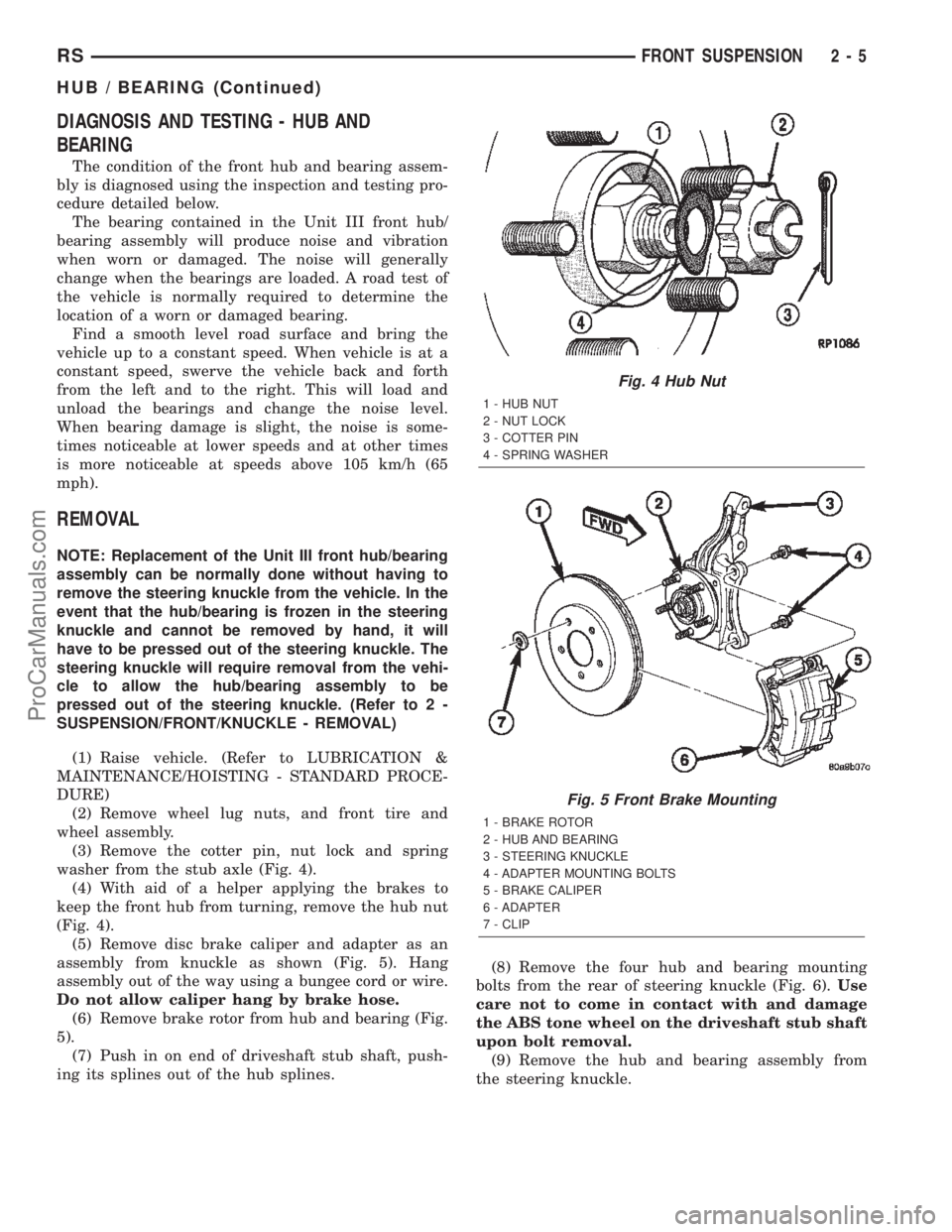
washer from the stub axle (Fig. 4).
(4) With aid of a helper applying the brakes to
keep the front hub from turning, remove the hub nut
(Fig. 4).
(5) Remove disc brake caliper and adapter as an
assembly from knuckle as shown (Fig. 5). Hang
assembly out of the way using a bungee cord or wire.
Do not allow caliper hang by brake hose.
(6) Remove brake rotor from hub and bearing (Fig.
5).
(7) Push in on end of driveshaft stub shaft, push-
ing its splines out of the hub splines.(8) Remove the four hub and bearing mounting
bolts from the rear of steering knuckle (Fig. 6).Use
care not to come in contact with and damage
the ABS tone wheel on the driveshaft stub shaft
upon bolt removal.
(9) Remove the hub and bearing assembly from
the steering knuckle.
Fig. 4 Hub Nut
1 - HUB NUT
2 - NUT LOCK
3 - COTTER PIN
4 - SPRING WASHER
Fig. 5 Front Brake Mounting
1 - BRAKE ROTOR
2 - HUB AND BEARING
3 - STEERING KNUCKLE
4 - ADAPTER MOUNTING BOLTS
5 - BRAKE CALIPER
6 - ADAPTER
7 - CLIP
RSFRONT SUSPENSION2-5
HUB / BEARING (Continued)
ProCarManuals.com
Page 30 of 2399
The center of the knuckle supports the hub and
bearing and axle shaft.
REMOVAL - STEERING KNUCKLE
(1) Raise vehicle. (Refer to LUBRICATION &
MAINTENANCE/HOISTING - STANDARD PROCE-
DURE)
(2) Remove the wheel and tire assembly from the
vehicle.
(3) Remove the cotter pin, nut lock and spring
washer from the end of the stub axle and hub nut
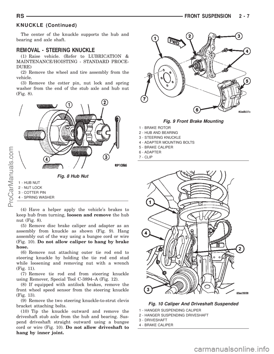
(Fig. 8).
(4) Have a helper apply the vehicle's brakes to
keep hub from turning,loosen and removethe hub
nut (Fig. 8).
(5) Remove disc brake caliper and adapter as an
assembly from knuckle as shown (Fig. 9). Hang
assembly out of the way using a bungee cord or wire
(Fig. 10).Do not allow caliper to hang by brake
hose.
(6) Remove nut attaching outer tie rod end to
steering knuckle by holding the tie rod end stud
while loosening and removing nut with a wrench
(Fig. 11).
(7) Remove tie rod end from steering knuckle
using Remover, Special Tool C-3894±A (Fig. 12).
(8) If equipped with antilock brakes, remove the
front wheel speed sensor from the steering knuckle
(Fig. 13).
(9) Remove the two steering knuckle-to-strut clevis
bracket attaching bolts.
(10) Tip the knuckle outward and remove the
driveshaft stub axle from the hub and bearing. Sus-
pend driveshaft straight outward using a bungee
cord or wire (Fig. 10).Do not allow driveshaft to
hang by inner joint.
Fig. 8 Hub Nut
1 - HUB NUT
2 - NUT LOCK
3 - COTTER PIN
4 - SPRING WASHER
Fig. 9 Front Brake Mounting
1 - BRAKE ROTOR
2 - HUB AND BEARING
3 - STEERING KNUCKLE
4 - ADAPTER MOUNTING BOLTS
5 - BRAKE CALIPER
6 - ADAPTER
7 - CLIP
Fig. 10 Caliper And Driveshaft Suspended
1 - HANGER SUSPENDING CALIPER
2 - HANGER SUSPENDING DRIVESHAFT
3 - DRIVESHAFT
4 - BRAKE CALIPER
RSFRONT SUSPENSION2-7
KNUCKLE (Continued)
ProCarManuals.com
Page 31 of 2399

(11) Remove ball joint nut using a power impact
wrench. Because the tapered stud is held sufficientlyin the knuckle at this time, it is not necessary to
hold the stud stationary to remove the nut.
(12) Reinstall the ball joint nut until the top of the
nut is even with the top of the ball joint stud. This
will keep the stud from distorting while the stud is
released from the knuckle in the following step.
CAUTION: Do not remove ball joint stud from steer-
ing knuckle using a hammer. Damage to the Alumi-
num knuckle, ball joint or control arm will result.
(13) Release ball joint stud from steering knuckle
using Remover, Special Tool C-4150A, as shown (Fig.
14). To ease Remover installation and use, it may
help to rotate the knuckle around so the inside of the
knuckle faces outward.
(14) Remove the nut from the top of the ball joint
stud.
(15) Remove the steering knuckle from the vehicle.
(16) If the hub and bearing needs to be trans-
ferred, remove the four bolts attaching the hub and
bearing to the knuckle, then remove the hub and
bearing.
INSPECTION - STEERING KNUCKLE
Inspect the knuckle for the following:
²Cracks or breaks
²Dents or damage
²Stress marks indicating a bend
The front suspension knuckle is not a repairable
component of the vehicles front suspension. If bent,
broken or damaged in any way, do not attempt to
straighten or repair the steering knuckle. It must be
replaced.
Fig. 11 Removing Tie Rod End Attaching Nut
1 - TIE ROD END
2 - STEERING KNUCKLE
3 - WRENCH
4 - SOCKET
5 - TIE ROD END STUD
Fig. 12 Tie Rod Removal With Tool C-3894-A
1 - OUTER TIE ROD
2 - SPECIAL TOOL C-3894-A
3 - STEERING KNUCKLE
Fig. 13 Front Wheel Speed Sensor
1 - MOUNTING BOLT
2 - WHEEL SPEED SENSOR
3 - STEERING KNUCKLE
2 - 8 FRONT SUSPENSIONRS
KNUCKLE (Continued)
ProCarManuals.com
Page 33 of 2399
(7) If equipped with antilock brakes, install wheel
speed sensor and mounting bolt on steering knuckle
(Fig. 13). Tighten the speed sensor bolt to a torque of
7 N´m (60 in. lbs.).
(8) Install brake rotor on hub and bearing (Fig. 9).
(9) Install disc brake caliper and adapter assembly
on steering knuckle. Install adapter amounting bolts
and tighten to 169 N´m (125 ft. lbs.).
(10) Clean any debris from the threads of the
outer C/V joint stub axle.
(11) Install the washer and hub nut on stub axle.
(12) Have a helper apply the vehicle's brakes to
keep hub from turning, then tighten hub nut to a
torque of 244 N´m (180 ft. lbs.).
(13) Install the spring wave washer on the end of
the stub axle.
(14) Install the hub nut lock, and anewcotter pin
(Fig. 8). Wrap cotter pin prongs tightly around the
hub nut lock.
(15) Install wheel and tire assembly. Install and
tighten the wheel mounting nuts in proper sequence
until all nuts are torqued to half the required speci-
fication. Then repeat the tightening sequence to the
full specified torque of 135 N´m (100 ft. lbs.).
(16) Lower vehicle.
(17) Set front wheel alignment camber and toe as
necessary. (Refer to 2 - SUSPENSION/WHEEL
ALIGNMENT - STANDARD PROCEDURE)
LOWER BALL JOINT
DESCRIPTION
The ball joint is an integral part of the lower con-
trol arm (Fig. 1). The ball joint has a tapered stud
that is pressed into the aluminum knuckle. The ball
joint stud is threaded on the end for a retainer nut.
The ball joint has a non-vented seal boot. The seal
boot has an integrated heat shield.
The ball joint used in the lower control arm of this
vehicle is a sealed-for-life ball joint and requires no
maintenance lubrication. The ball joint has been
lubricated-for-life during the manufacturing process.
A special fitting cap is installed on the fill port. This
cap must not be removed and replaced with a com-
mon zirc fitting. The special cap is there to eliminate
the possibility of lubrication latter during the ball
joints life, thus damaging the non-vented seal boot.
NOTE: The ball joint does not require any type of
additional lubrication for the life of the vehicle. No
attempt should be made to ever add any lubrication
to the lower ball joint.
OPERATION
The ball joint is a pivotal joint on the lower control
arm that allows the knuckle to move up and down,
and turn with ease.
DIAGNOSIS AND TESTING - LOWER BALL
JOINT
With the weight of the vehicle resting on the road
wheels, grasp the special fitting cap on the bottom of
the ball joint and with no mechanical assistance or
added force, attempt to rotate the grease fitting.
If the ball joint is worn, the grease fitting will
rotate easily. If movement is noted, replacement of
the control arm is recommended.
LOWER BALL JOINT SEAL
BOOT
DESCRIPTION - EXPORT
The lower ball joint seal boot is a two piece unit. It
consists of the seal boot, plus a separate shield that
is located in a groove at the top of the seal boot.
NOTE: The seal boot should only be replaced if
damaged during vehicle service. The entire lower
control arm should be replaced if the joint has been
contaminated.
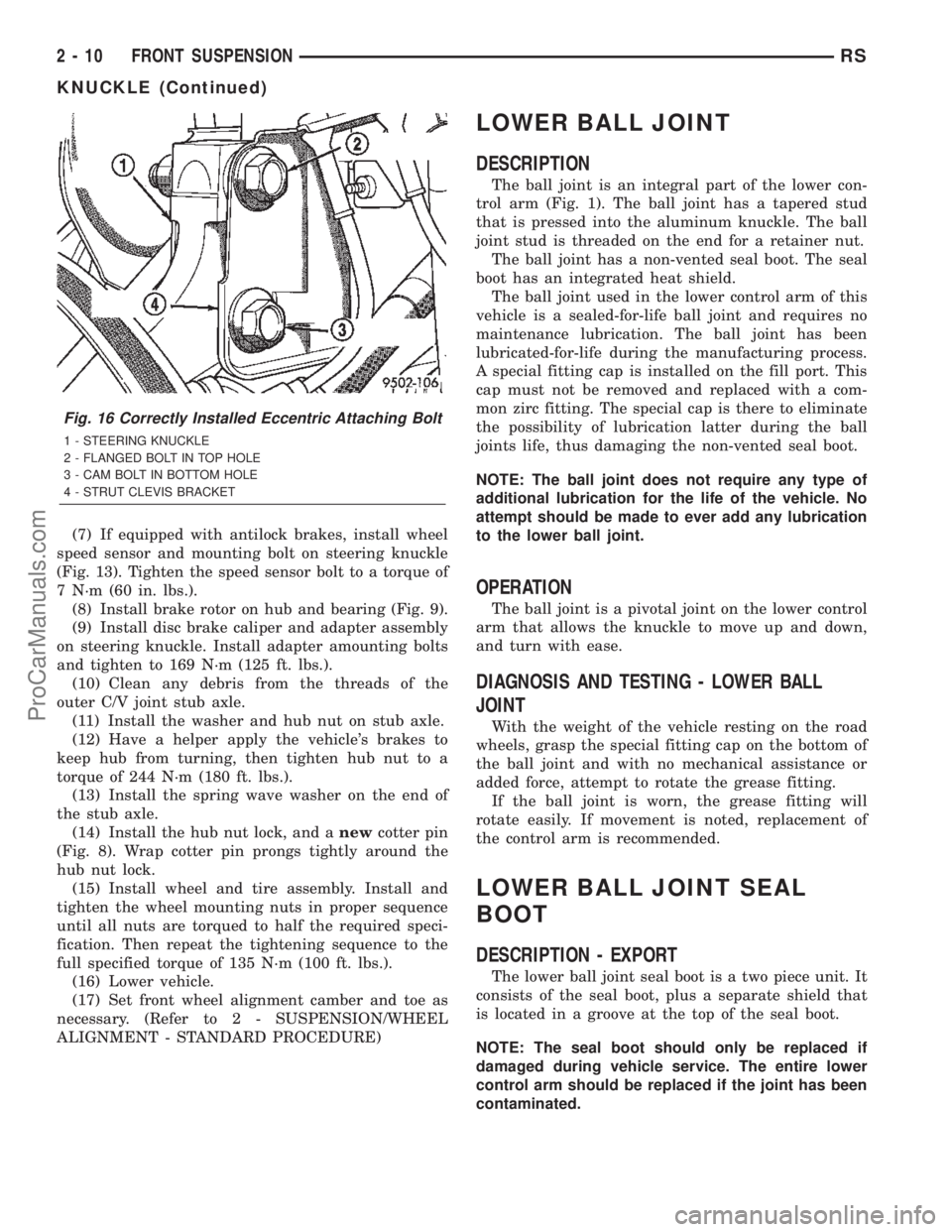
Fig. 16 Correctly Installed Eccentric Attaching Bolt
1 - STEERING KNUCKLE
2 - FLANGED BOLT IN TOP HOLE
3 - CAM BOLT IN BOTTOM HOLE
4 - STRUT CLEVIS BRACKET
2 - 10 FRONT SUSPENSIONRS
KNUCKLE (Continued)
ProCarManuals.com