cooling system CHRYSLER VOYAGER 2003 Owner's Guide
[x] Cancel search | Manufacturer: CHRYSLER, Model Year: 2003, Model line: VOYAGER, Model: CHRYSLER VOYAGER 2003Pages: 2177, PDF Size: 59.81 MB
Page 295 of 2177
(5) Install the radiator upper hose.
(6) Fill the cooling system. (Refer to 7 - COOLING
- STANDARD PROCEDURE)
WATER PUMP INLET TUBE -
3.3/3.8L
REMOVAL
(1) Drain the cooling system. (Refer to 7 - COOL-
ING - STANDARD PROCEDURE)
(2) Raise vehicle on hoist and remove the belt
splash shield.
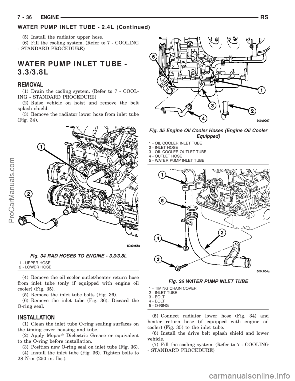
(3) Remove the radiator lower hose from inlet tube
(Fig. 34).
(4) Remove the oil cooler outlet/heater return hose
from inlet tube (only if equipped with engine oil
cooler) (Fig. 35).
(5) Remove the inlet tube bolts (Fig. 36).
(6) Remove the inlet tube (Fig. 36). Discard the
O-ring seal.
INSTALLATION
(1) Clean the inlet tube O-ring sealing surfaces on
the timing cover housing and tube.
(2) Apply MopartDielectric Grease or equivalent
to the O-ring before installation.
(3) Position new O-ring seal on inlet tube (Fig. 36).
(4) Install the inlet tube (Fig. 36). Tighten bolts to
28 N´m (250 in. lbs.).(5) Connect radiator lower hose (Fig. 34) and
heater return hose (if equipped with engine oil
cooler) (Fig. 35) to the inlet tube.
(6) Install the drive belt splash shield and lower
vehicle.
(7) Fill the cooling system. (Refer to 7 - COOLING
- STANDARD PROCEDURE)
Fig. 34 RAD HOSES TO ENGINE - 3.3/3.8L
1 - UPPER HOSE
2 - LOWER HOSE
Fig. 35 Engine Oil Cooler Hoses (Engine Oil Cooler
Equipped)
1 - OIL COOLER INLET TUBE
2 - INLET HOSE
3 - OIL COOLER OUTLET TUBE
4 - OUTLET HOSE
5 - WATER PUMP INLET TUBE
Fig. 36 WATER PUMP INLET TUBE
1 - TIMING CHAIN COVER
2 - INLET TUBE
3 - BOLT
4 - BOLT
5 - O-RING
7 - 36 ENGINERS
WATER PUMP INLET TUBE - 2.4L (Continued)
ProCarManuals.com
Page 327 of 2177
NOTE: PCM Inputs:
²Air Conditioning Pressure Transducer
²Ambient temperature Sensor
²ASD Relay
²Battery Temperature Sensor (NGC)
²Battery Voltage
²Brake Switch
²Camshaft Position Sensor
²Crankshaft Position Sensor
²Distance Sensor (from transmission control mod-
ule)
²EGR Position Feedback
²Engine Coolant Temperature Sensor
²Heated Oxygen Sensors
²Ignition sense
²Intake Air Temperature Sensor
²Knock Sensor
²Leak Detection Pump Feedback
²Manifold Absolute Pressure (MAP) Sensor
²Park/Neutral
²PCI Bus
²Power Steering Pressure Switch
²Proportional Purge Sense
²SCI Receive
²Speed Control
²Throttle Position Sensor
²Torque Management Input
²Transaxle Control Module (3.3/3.8L Only)
²Transmission Control Relay (Switched B+) (2.4L
Only)
²Transmission Pressure Switches (2.4L Only)
²Transmission Temperature Sensor (2.4L Only)
²Transmission Input Shaft Speed Sensor (2.4L
Only)
²Transmission Output Shaft Speed Sensor (2.4L
Only)
²Transaxle Gear Engagement
²Vehicle Speed
NOTE: PCM Outputs:
²Air Conditioning Clutch Relay
²Automatic Shut Down (ASD) and Fuel Pump
Relays
²Data Link Connector (PCI and SCI Transmit)
²Double Start Override
²EGR Solenoid
²Fuel Injectors
²Generator Field
²High Speed Fan Relay
²Idle Air Control Motor
²Ignition Coils
²Leak Detection Pump
²Low Speed Fan Relay
²MTV Actuator
²Proportional Purge Solenoid²SRV Valve
²Speed Control Relay
²Speed Control Vent Relay
²Speed Control Vacuum Relay
²8 Volt Output
²5 Volt Output
²Torque Reduction Request
²Transmission Control Relay (2.4L Only)
²Transmission Solenoids (2.4L Only)
²Vehicle Speed
Based on inputs it receives, the powertrain control
module (PCM) adjusts fuel injector pulse width, idle
speed, ignition timing, and canister purge operation.
The PCM regulates the cooling fans, air conditioning
and speed control systems. The PCM changes gener-
ator charge rate by adjusting the generator field.
The PCM adjusts injector pulse width (air-fuel
ratio) based on the following inputs.
²Battery Voltage
²Intake Air Temperature Sensor
²Engine Coolant Temperature
²Engine Speed (crankshaft position sensor)
²Exhaust Gas Oxygen Content (heated oxygen
sensors)
²Manifold Absolute Pressure
²Throttle Position
The PCM adjusts engine idle speed through the
idle air control motor based on the following inputs.
²Brake Switch
²Engine Coolant Temperature
²Engine Speed (crankshaft position sensor)
²Park/Neutral
²Transaxle Gear Engagement
²Throttle Position
²Vehicle Speed
The PCM adjusts ignition timing based on the fol-
lowing inputs.
²Intake Air Temperature
²Engine Coolant Temperature
²Engine Speed (crankshaft position sensor)
²Knock Sensor
²Manifold Absolute Pressure
²Park/Neutral
²Transaxle Gear Engagement
²Throttle Position
The automatic shut down (ASD) and fuel pump
relays are mounted externally, but turned on and off
by the powertrain control module through the same
circuit.
The camshaft and crankshaft signals are sent to
the powertrain control module. If the PCM does not
receive both signals within approximately one second
of engine cranking, it deactivates the ASD and fuel
pump relays. When these relays are deactivated,
power is shut off to the fuel injectors, ignition coils,
8E - 12 ELECTRONIC CONTROL MODULESRS
POWERTRAIN CONTROL MODULE (Continued)
ProCarManuals.com
Page 359 of 2177
CHARGING
TABLE OF CONTENTS
page page
CHARGING
DESCRIPTION - CHARGING SYSTEM.......20
OPERATION - CHARGING SYSTEM.........20
DIAGNOSIS AND TESTING - ON-BOARD
DIAGNOSTIC SYSTEM.................21
SPECIFICATIONS
GENERATOR........................22
TORQUE............................22
SPECIFICATIONS - BATTERY
TEMPERATURE SENSOR...............22
SPECIAL TOOLS.......................23
BATTERY TEMPERATURE SENSOR
DESCRIPTION.........................23
OPERATION...........................23
REMOVAL.............................23
GENERATOR
DESCRIPTION.........................23OPERATION...........................23
REMOVAL
REMOVAL - 2.4L......................23
REMOVAL - 3.3/3.8L...................24
INSTALLATION
INSTALLATION - 2.4L..................24
INSTALLATION - 3.3/3.8L................24
GENERATOR DECOUPLER PULLEY
DESCRIPTION.........................25
OPERATION...........................25
DIAGNOSIS AND TESTING - GENERATOR
DECOUPLER PULLEY..................25
REMOVAL.............................26
INSTALLATION.........................26
VOLTAGE REGULATOR
DESCRIPTION.........................27
OPERATION...........................27
CHARGING
DESCRIPTION - CHARGING SYSTEM
The charging system consists of:
²Generator
²Decoupler Pulley (If equipped)
²Electronic Voltage Regulator (EVR) circuitry
within the Powertrain Control Module (PCM)
²Ignition switch (refer to the Ignition System sec-
tion for information)
²Battery (refer to the Battery section for informa-
tion)
²Ambient Air Temperature (If equipped)
²Inlet Air Temperature (calculated battery tem-
perature)(If equipped)
²Voltmeter (refer to the Instrument Cluster sec-
tion for information if equipped)
²Wiring harness and connections (refer to the
Wiring section for information)
²Accessory drive belt (refer to the Cooling section
for more information)
²Battery Temperature sensor (if equipped)
OPERATION - CHARGING SYSTEM
The charging system is turned on and off with the
ignition switch. The system is on when the engine is
running and the ASD relay is energized. The ASD
relay is energized when the PCM grounds the ASD
control circuit. (SBEC vehicles) This voltage is con-
nected through the PCM or IPM (intelligent powermodule) (if equipped) and supplied to one of the gen-
erator field terminals (Gen. Source +) at the back of
the generator.
The generator is driven by the engine through a
serpentine belt and pulley or decoupler pulley
arrangement.
The amount of DC current produced by the gener-
ator is controlled by the EVR (field control) circuitry
contained within the PCM. This circuitry is con-
nected in series with the second rotor field terminal
and ground.
(SBEC vehicles) An Inlet air temperature sensor is
used to calculate the temperature near the battery.
This temperature data, along with data from moni-
tored line voltage (battery voltage sense circuit), is
used by the PCM to vary the battery charging rate.
This is done by cycling the ground path to control the
strength of the rotor magnetic field. The PCM then
compensates and regulates generator current output
accordingly to maintain system voltage at the tar-
geted system voltage based on battery temperature.
All vehicles are equipped with On-Board Diagnos-
tics (OBD). All OBD-sensed systems, including EVR
(field control) circuitry, are monitored by the PCM.
Each monitored circuit is assigned a Diagnostic Trou-
ble Code (DTC). The PCM will store a DTC in elec-
tronic memory for certain failures it detects and
illuminate the (MIL) lamp. Refer to On-Board Diag-
nostics in the Electronic Control Modules(Refer to 8 -
ELECTRICAL/ELECTRONIC CONTROL MOD-
8F - 20 CHARGINGRS
ProCarManuals.com
Page 361 of 2177

(4) Inspect generator mounting bolts for tightness.
Replace or tighten bolts if required. Refer to the Gen-
erator Removal/Installation section of this group for
torque specifications (Refer to 8 - ELECTRICAL/
CHARGING - SPECIFICATIONS).
(5) Inspect generator drive belt condition and ten-
sion. Tighten or replace belt as required. Refer to
Belt Tension Specifications(Refer to 7 - COOLING/
ACCESSORY DRIVE - SPECIFICATIONS).
(6) Inspect decoupler pulley (if equipped). Ensure
decoupler pulley is driving the alternator rotor.
(7) Inspect automatic belt tensioner (if equipped).
Refer to the Cooling System for more information.
(8) Inspect generator electrical connections at gen-
erator field, battery output, and ground terminal (if
equipped). Also check generator ground wire connec-
tion at engine (if equipped). They should all be clean
and tight. Repair as required.SPECIFICATIONS
GENERATOR
Type Engine Minimun Test
Amperage
Denso 2.4 L 80 Amp (HOT)
Denso 3.3/3.8L 100 Amp or 115
Amp (HOT)
Test Specification:
1. Engine RPM : 2500 RPM 20 RPM (HOT)
2. Voltage Output : 14.0 V 0.5 V
3. Field Current : 5 amps 0.1 amps
Part number is located on the side of the generator.
TORQUE
DESCRIPTION N´m Ft. Lbs. In. Lbs.
Battery Hold Down Clamp
Bolt20 14.7 180
Generator B+ Nut 12.4 9.2 110
Battery Terminal Nut 4 35
Generator Mounting Bolt
2.4L28.2 20.8 250
Generator Mounting Bolts
3.3/3.8L54.2 40
Starter Solenoid Battery
Nut 3.3/3.8L11.3 8.3 100
Generator Decoupler 109.8 81
SPECIFICATIONS - BATTERY TEMPERATURE SENSOR
ÉC ÉF K-Ohms Min. K-Ohms Max.
(40) (40) 291.4 381.7
(20) (4) 85.8 108.4
20 68 11.4 13.6
25 77 9.1 10.9
120 248 0.37 0.41
130 266 0.28 0.32
8F - 22 CHARGINGRS
CHARGING (Continued)
ProCarManuals.com
Page 363 of 2177

REMOVAL - 3.3/3.8L
(1) Release hood latch and open hood.
(2) Disconnect battery negative cable.
(3) Disconnect the push-in field wire connector
from back of generator.
(4) Remove nut holding B+ wire terminal to back
of generator.
(5) Separate B+ terminal from generator.
(6) Raise vehicle and support.
(7) Remove the right front lower splash shield.
(8) Remove accessory drive belt, refer to the Cool-
ing System section for proper procedures.
(9) Remove the lower oil dip stick tube bolt (Fig.
1).
(10) Remove wiring harness from the oil dip stick
tube
(11) Remove the 3 mounting bolts.
(12) Lower vehicle.
(13) Remove oil dip stick tube from vehicle.
(14) Roll and remove the generator from vehicle
(Fig. 2).
INSTALLATION
INSTALLATION - 2.4L
(1) Install the generator.
(2) Install the accessory drive belt, refer to the
Cooling System section for proper procedures.
(3) Connect B+ terminal to generator.
(4) Install nut holding B+ wire terminal to back of
generator.(5) Connect the push-in field wire connector to
back of generator.
(6) Install the EVAP Purge solenoid to its bracket.
(7) Install the Air Box, refer to the Engine/Air
Cleaner for more information.
(8) Connect the Inlet Air Temperature sensor.
(9) Connect battery negative cable.
INSTALLATION - 3.3/3.8L
(1) Roll and place generator in position on vehicle
(Fig. 2).
(2) Install upper bolts to hold generator in place.
(3) Lubricate the o-ring. Install oil dip stick tube.
(4) Install the upper oil dip stick tube bolt.
(5) Place B+ terminal in position on generator.
(6) Install nut to hold B+ wire terminal to back of
generator.
(7) Connect the push-in field wire connector into
back of generator.
(8) Raise vehicle and support.
(9) Install the lower mounting bolt and tighten.
(10) Install the lower oil dip stick tube bolt and
tighten (Fig. 1).
(11) Install accessory drive belt, refer to the Cool-
ing System section for proper procedures.
(12) Install the right front lower splash shield.
(13) Lower vehicle.
(14) Install wiring harness to the oil dip stick tube
(15) Connect battery negative cable.
(16) Verify generator output rate.
Fig. 1 DIP STICK LOWER BOLT
Fig. 2 GENERATOR 3.3/3.8L
8F - 24 CHARGINGRS
GENERATOR (Continued)
ProCarManuals.com
Page 365 of 2177

REMOVAL
(1) Release hood latch and open hood.
(2) Disconnect battery negative cable.
(3) Raise vehicle and support.
(4) Remove the right front lower splash shield.
(5) Remove accessory drive belt, refer to the Cool-
ing System section for proper procedures (Fig. 4).
(6) Lower vehicle.
(7) Remove the Air Box, refer to the Engine section
for more information.
(8) Remove the decoupler pulley cover.
(9) Use Special Tool #8433 (Fig. 6) to loosen the
Generator Decoupler (Fig. 5).
(10) Remove the tool.
(11) Remove the Generator Decoupler.
INSTALLATION
(1) Install the Generator Decoupler to the genera-
tor shaft.
(2) Use Special Tool #8433 (Fig. 6) to tighten the
Generator Decoupler (Fig. 7). Refer to the torque
chart for the proper torque.
(3) Install a new decoupler pulley cover.
(4) Install the Air Box, refer to the Engine section
for more information.(5) Raise vehicle and support.
(6) Install accessory drive belt, refer to the Cooling
System section for proper procedures (Fig. 4).
(7) Install the right front lower splash shield.
(8) Lower vehicle.
(9) Connect battery negative cable.
Fig. 4 DRIVE BELT 3.3/3.8L
Fig. 5 DECOUPLER REMOVAL (LITENS)
Fig. 6 SPECIAL TOOL 8433 AND DECOUPLER
8F - 26 CHARGINGRS
GENERATOR DECOUPLER PULLEY (Continued)
ProCarManuals.com
Page 1189 of 2177

Calibrate the tester according to the manufactur-
er's instructions. The shop air source for testing
should maintain 483 kPa (70 psi) minimum, 1,379
kPa (200 psi) maximum, with 552 kPa (80 psi) rec-
ommended.
Perform the test procedures on each cylinder
according to the tester manufacturer's instructions.
While testing, listen for pressurized air escaping
through the throttle body, tailpipe and oil filler cap
opening. Check for bubbles in the coolant.
All gauge pressure indications should be equal,
with no more than 25% leakage per cylinder.
FOR EXAMPLE:At 552 kPa (80 psi) input pres-
sure, a minimum of 414 kPa (60 psi) should be main-
tained in the cylinder.
STANDARD PROCEDURE
STANDARD PROCEDURE - ENGINE CORE AND
OIL GALLERY PLUGS
Using a blunt tool such as a drift and a hammer,
strike the bottom edge of the cup plug. With the cup
plug rotated, grasp firmly with pliers or other suit-
able tool and remove plug (Fig. 2).
CAUTION: Do not drive cup plug into the casting as
restricted cooling can result and cause serious
engine problems.Thoroughly clean inside of cup plug hole in cylin-
der block or head. Be sure to remove old sealer.
Lightly coat inside of cup plug hole with Mopart
Stud and Bearing Mount. Make certain the new plug
is cleaned of all oil or grease. Using proper drive
plug, drive plug into hole so that the sharp edge of
the plug is at least 0.5 mm (0.020 in.) inside the
lead-in chamfer.
It is not necessary to wait for curing of the sealant.
The cooling system can be refilled and the vehicle
placed in service immediately.
STANDARD PROCEDURE - REPAIR OF
DAMAGED OR WORN THREADS
Damaged or worn threads (excluding spark plug
and camshaft bearing cap attaching threads) can be
repaired. Essentially, this repair consists of drilling
out worn or damaged threads, tapping the hole with
a special Heli-Coil Tap, (or equivalent) and installing
an insert into the tapped hole. This brings the hole
back to its original thread size.
CAUTION: Be sure that the tapped holes maintain
the original center line.
Heli-Coil tools and inserts are readily available
from automotive parts jobbers.
STANDARD PROCEDURE - HYDROSTATIC
LOCKED ENGINE
When an engine is suspected to be hydrostatically
locked, regardless of what caused the problem, the
following steps should be used.
CAUTION: DO NOT use starter motor to rotate the
engine, severe damage may occur.
(1) Inspect air cleaner, induction system and
intake manifold to insure system is dry and clear of
foreign material.
(2) Remove negative battery cable.
(3) Place a shop towel around the spark plugs
when removing them from the engine. This will catch
any fluid that may possibly be in the cylinder under
pressure.
(4) With all spark plugs removed, rotate engine
crankshaft using a breaker bar and socket.
(5) Identify the fluid in the cylinder(s) (i.e., cool-
ant, fuel, oil or other).
(6) Make sure all fluid has been removed from the
cylinders. Inspect engine for damage (i.e., connecting
rods, pistons, valves, etc.)
(7) Repair engine or components as necessary to
prevent this problem from re-occurring.
Fig. 2 Core Hole Plug Removal
1 - CYLINDER BLOCK
2 - REMOVE PLUG WITH PLIERS
3 - STRIKE HERE WITH HAMMER
4 - DRIFT PUNCH
5 - CUP PLUG
9 - 10 ENGINE 2.4LRS
ENGINE 2.4L (Continued)
ProCarManuals.com
Page 1192 of 2177

REMOVAL - ENGINE ASSEMBLY
(1) Perform fuel pressure release procedure (Refer
to 14 - FUEL SYSTEM/FUEL DELIVERY - STAN-
DARD PROCEDURE)
(2) Disconnect battery negative cable.
(3) Remove air cleaner housing and inlet tube.
(4) Disconnect the fuel line from fuel rail. (Refer to
14 - FUEL SYSTEM/FUEL DELIVERY/FUEL LINES
- STANDARD PROCEDURE)
(5) Disconnect all vacuum hoses.
(6) Drain cooling system. (Refer to 7 - COOLING -
STANDARD PROCEDURE)
(7) Remove radiator fans. (Refer to 7 - COOLING/
ENGINE/RADIATOR FAN - REMOVAL)
(8) Remove radiator upper and lower hoses.
NOTE: When the transaxle cooler lines are removed
from the rolled-groove type fittings at the transaxle,
damage to the inner wall of the hose will occur. To
prevent prevent potential leakage, the cooler hoses
must be cut off flush at the transaxle fitting, and a
service cooler hose splice kit must be installed
upon reassembly.(9) Using a blade or suitable hose cutter, cut trans-
axle oil cooler lines off flush with fittings. Plug cooler
lines and fittings to prevent debris from entering
transaxle or cooler circuit. A service splice kit will be
installed upon reassembly.
(10) Disconnect transmission shift linkage and
electrical connectors.
(11) Disconnect throttle body linkage.
(12) Disconnect engine wiring harness.
(13) Disconnect heater hoses from heater (Fig. 5).
(14) Discharge air conditioning system. (Refer to
24 - HEATING & AIR CONDITIONING/PLUMBING
- STANDARD PROCEDURE)
(15) Hoist vehicle and remove front wheels and
tires.
(16) Remove accessory drive belt splash shield.
(17) Remove accessory drive belts. (Refer to 7 -
COOLING/ACCESSORY DRIVE/DRIVE BELTS -
REMOVAL)
Fig. 5 HEATER HOSES - 2.4L
1 - HEATER HOSES TO HEATER 3 - HEATER HOSE TO ENGINE - SUPPLY AND RETURN
2 - BOLT - HEATER TUBE SUPPORT
RSENGINE 2.4L9-13
ENGINE 2.4L (Continued)
ProCarManuals.com
Page 1195 of 2177

INSTALLATION - ENGINE ASSEMBLY
(1) Position engine and transmission assembly
under vehicle and slowly lower the vehicle over the
engine and transmission.
(2) Align engine and transmission mounts to
attaching points. Install mounting bolts at the right
(Fig. 9) and left mounts (Fig. 10).
(3) Remove safety straps.
(4) Slowly raise vehicle enough to remove the
engine dolly and cradle Special Tools 6135 and 6710.
(5) Install rear mount bracket and rear mount
through bolt. (Refer to 9 - ENGINE/ENGINE
MOUNTING/REAR MOUNT - INSTALLATION)
(6) Install the flex plate to torque converter bolts.
(7) Install structural collar. (Refer to 9 - ENGINE/
ENGINE BLOCK/STRUCTURAL COVER - INSTAL-
LATION)
(8) Install front mount bracket and front mount
through bolt. (Refer to 9 - ENGINE/ENGINE
MOUNTING/FRONT MOUNT - INSTALLATION)
(9) Connect exhaust system to manifold (Fig. 7).
(10) Install crossmember cradle plate (Fig. 6).
(11) Install new oil filter.
(12) Install power steering pump and bracket.
(13) Connect power steering supply line to pump
and remove pinch-off pliers.(14) Connect A/C compressor hoses to compressor.
(15) Install accessory drive belts. (Refer to 7 -
COOLING/ACCESSORY DRIVE/DRIVE BELTS -
INSTALLATION)
(16) Install axle shafts. (Refer to 3 - DIFFEREN-
TIAL & DRIVELINE/HALF SHAFT - INSTALLA-
TION)
(17) Install accessory drive belt splash shield.
(18) Install front wheels and tires.
(19) Remove plugs from transmission cooler hoses
and install transaxle oil cooler line service splice kit.
Refer to instructions included with kit.
(20) Connect the transaxle shift linkage and elec-
trical connectors.
(21) Connect heater hoses (Fig. 5).
(22) Install ground straps.
(23) Connect all engine and throttle body electrical
connections.
(24) Connect all vacuum lines.
(25) Connect the throttle cables.
(26) Connect the fuel line. (Refer to 14 - FUEL
SYSTEM/FUEL DELIVERY/QUICK CONNECT FIT-
TING - STANDARD PROCEDURE)
(27) Connect radiator lower and upper hoses.
(28) Install radiator fans. (Refer to 7 - COOLING/
ENGINE/RADIATOR FAN - INSTALLATION)
(29) Fill cooling system. (Refer to 7 - COOLING -
STANDARD PROCEDURE)
(30) Connect battery cables.
(31) Install air cleaner and inlet hose.
(32) Fill engine crankcase with proper oil to cor-
rect level.
Fig. 9 RIGHT MOUNT TO RAIL AND ENGINE
1 - BOLT - MOUNT TO RAIL 68 N´m (50 ft. lbs.)
2 - BOLT - MOUNT TO ENGINE 54 N´m (40 ft. lbs.)
3 - BOLT - MOUNT TO RAIL (HORIZONTAL) 68 N´m (50 ft. lbs.)
4 - RIGHT ENGINE MOUNT
5 - RIGHT FRAME RAIL
Fig. 10 LEFT MOUNT TO FRAME BRACKET
1 - FRAME BRACKET
2 - FRAME RAIL - LEFT
3 - BOLT
4 - TRANSAXLE MOUNT
9 - 16 ENGINE 2.4LRS
ENGINE 2.4L (Continued)
ProCarManuals.com
Page 1204 of 2177
²Excessive steam (white smoke) emitting from
exhaust
²Coolant foaming
CYLINDER-TO-CYLINDER LEAKAGE TEST
To determine if an engine cylinder head gasket is
leaking between adjacent cylinders, follow the proce-
dures in Cylinder Compression Pressure Test (Refer
to 9 - ENGINE - DIAGNOSIS AND TESTING). An
engine cylinder head gasket leaking between adja-
cent cylinders will result in approximately a 50±70%
reduction in compression pressure.
CYLINDER-TO-WATER JACKET LEAKAGE TEST
WARNING: USE EXTREME CAUTION WHEN THE
ENGINE IS OPERATING WITH COOLANT PRES-
SURE CAP REMOVED.
VISUAL TEST METHOD
With the engine cool, remove the coolant pressure
cap. Start the engine and allow it to warm up until
thermostat opens.
If a large combustion/compression pressure leak
exists, bubbles will be visible in the coolant.COOLING SYSTEM TESTER METHOD
WARNING: WITH COOLING SYSTEM TESTER IN
PLACE, PRESSURE WILL BUILD UP FAST. EXCES-
SIVE PRESSURE BUILT UP, BY CONTINUOUS
ENGINE OPERATION, MUST BE RELEASED TO A
SAFE PRESSURE POINT. NEVER PERMIT PRES-
SURE TO EXCEED 138 kPa (20 psi).
Install Cooling System Tester 7700 or equivalent to
pressure cap neck. Start the engine and observe the
tester's pressure gauge. If gauge pulsates with every
power stroke of a cylinder a combustion pressure
leak is evident.
CHEMICAL TEST METHOD
Combustion leaks into the cooling system can also
be checked by using Bloc-Chek Kit C-3685-A or
equivalent. Perform test following the procedures
supplied with the tool kit.
REMOVAL - CYLINDER HEAD
(1) Perform fuel system pressure release procedure
before attempting any repairs.(Refer to 14 -
FUEL SYSTEM/FUEL DELIVERY - SPECIFICA-
TIONS)
(2) Disconnect battery negative cable.
(3) Drain cooling system. (Refer to 7 - COOLING -
STANDARD PROCEDURE)
(4) Remove air filter housing and inlet tube.
(5) Remove upper intake manifold. (Refer to 9 -
ENGINE/MANIFOLDS/INTAKE MANIFOLD -
REMOVAL)
(6) Remove heater tube support bracket from cyl-
inder head.
(7) Disconnect radiator upper and heater supply
hoses from intake manifold water outlet connections.
(8) Remove accessory drive belts. (Refer to 7 -
COOLING/ACCESSORY DRIVE/DRIVE BELTS -
REMOVAL)
(9) Raise vehicle and remove exhaust pipe from
manifold.
(10) Remove power steering pump reservoir and
line support bracket from lower intake manifold and
set aside. Do not disconnect lines.
(11) Remove ignition coil and wires from engine.
(12) Disconnect cam sensor and fuel injector wir-
ing connectors.
(13) Remove timing belt and camshaft sprockets.
(Refer to 9 - ENGINE/VALVE TIMING/TIMING
BELT/CHAIN AND SPROCKETS - REMOVAL)
(14) Remove timing belt idler pulley and rear tim-
ing belt cover. (Refer to 9 - ENGINE/VALVE TIM-
ING/TIMING BELT / CHAIN COVER(S) -
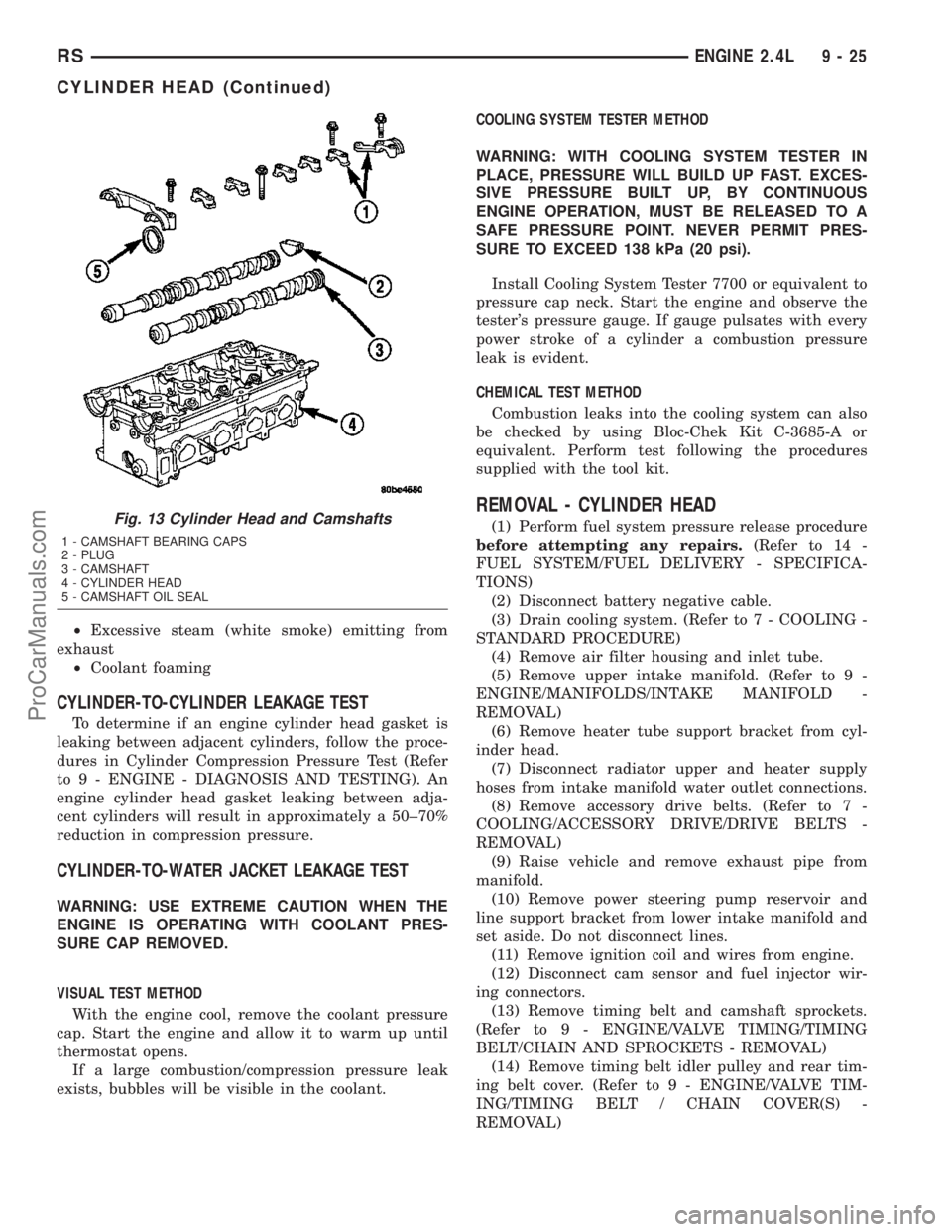
REMOVAL)Fig. 13 Cylinder Head and Camshafts
1 - CAMSHAFT BEARING CAPS
2 - PLUG
3 - CAMSHAFT
4 - CYLINDER HEAD
5 - CAMSHAFT OIL SEAL
RSENGINE 2.4L9-25
CYLINDER HEAD (Continued)
ProCarManuals.com