Crankshaft timing CHRYSLER VOYAGER 2003 Service Manual
[x] Cancel search | Manufacturer: CHRYSLER, Model Year: 2003, Model line: VOYAGER, Model: CHRYSLER VOYAGER 2003Pages: 2177, PDF Size: 59.81 MB
Page 327 of 2177
NOTE: PCM Inputs:
²Air Conditioning Pressure Transducer
²Ambient temperature Sensor
²ASD Relay
²Battery Temperature Sensor (NGC)
²Battery Voltage
²Brake Switch
²Camshaft Position Sensor
²Crankshaft Position Sensor
²Distance Sensor (from transmission control mod-
ule)
²EGR Position Feedback
²Engine Coolant Temperature Sensor
²Heated Oxygen Sensors
²Ignition sense
²Intake Air Temperature Sensor
²Knock Sensor
²Leak Detection Pump Feedback
²Manifold Absolute Pressure (MAP) Sensor
²Park/Neutral
²PCI Bus
²Power Steering Pressure Switch
²Proportional Purge Sense
²SCI Receive
²Speed Control
²Throttle Position Sensor
²Torque Management Input
²Transaxle Control Module (3.3/3.8L Only)
²Transmission Control Relay (Switched B+) (2.4L
Only)
²Transmission Pressure Switches (2.4L Only)
²Transmission Temperature Sensor (2.4L Only)
²Transmission Input Shaft Speed Sensor (2.4L
Only)
²Transmission Output Shaft Speed Sensor (2.4L
Only)
²Transaxle Gear Engagement
²Vehicle Speed
NOTE: PCM Outputs:
²Air Conditioning Clutch Relay
²Automatic Shut Down (ASD) and Fuel Pump
Relays
²Data Link Connector (PCI and SCI Transmit)
²Double Start Override
²EGR Solenoid
²Fuel Injectors
²Generator Field
²High Speed Fan Relay
²Idle Air Control Motor
²Ignition Coils
²Leak Detection Pump
²Low Speed Fan Relay
²MTV Actuator
²Proportional Purge Solenoid²SRV Valve
²Speed Control Relay
²Speed Control Vent Relay
²Speed Control Vacuum Relay
²8 Volt Output
²5 Volt Output
²Torque Reduction Request
²Transmission Control Relay (2.4L Only)
²Transmission Solenoids (2.4L Only)
²Vehicle Speed
Based on inputs it receives, the powertrain control
module (PCM) adjusts fuel injector pulse width, idle
speed, ignition timing, and canister purge operation.
The PCM regulates the cooling fans, air conditioning
and speed control systems. The PCM changes gener-
ator charge rate by adjusting the generator field.
The PCM adjusts injector pulse width (air-fuel
ratio) based on the following inputs.
²Battery Voltage
²Intake Air Temperature Sensor
²Engine Coolant Temperature
²Engine Speed (crankshaft position sensor)
²Exhaust Gas Oxygen Content (heated oxygen
sensors)
²Manifold Absolute Pressure
²Throttle Position
The PCM adjusts engine idle speed through the
idle air control motor based on the following inputs.
²Brake Switch
²Engine Coolant Temperature
²Engine Speed (crankshaft position sensor)
²Park/Neutral
²Transaxle Gear Engagement
²Throttle Position
²Vehicle Speed
The PCM adjusts ignition timing based on the fol-
lowing inputs.
²Intake Air Temperature
²Engine Coolant Temperature
²Engine Speed (crankshaft position sensor)
²Knock Sensor
²Manifold Absolute Pressure
²Park/Neutral
²Transaxle Gear Engagement
²Throttle Position
The automatic shut down (ASD) and fuel pump
relays are mounted externally, but turned on and off
by the powertrain control module through the same
circuit.
The camshaft and crankshaft signals are sent to
the powertrain control module. If the PCM does not
receive both signals within approximately one second
of engine cranking, it deactivates the ASD and fuel
pump relays. When these relays are deactivated,
power is shut off to the fuel injectors, ignition coils,
8E - 12 ELECTRONIC CONTROL MODULESRS
POWERTRAIN CONTROL MODULE (Continued)
ProCarManuals.com
Page 396 of 2177
IGNITION CONTROL
TABLE OF CONTENTS
page page
IGNITION CONTROL
DESCRIPTION - IGNITION SYSTEM..........1
OPERATION - IGNITION SYSTEM...........1
SPECIFICATIONS
TORQUE.............................2
SPARK PLUG CABLE RESISTANCE........2
SPARK PLUG.........................2
FIRING ORDER........................3
AUTO SHUT DOWN RELAY
DESCRIPTION..........................3
OPERATION............................3
CAMSHAFT POSITION SENSOR
DESCRIPTION..........................3
OPERATION............................3
REMOVAL
REMOVAL - 2.4L.......................4
REMOVAL - 3.3/3.8L....................5
INSTALLATION
INSTALLATION - 2.4L...................5
INSTALLATION - 3.3/3.8L.................6
IGNITION COIL
DESCRIPTION..........................6
OPERATION............................6
REMOVAL
REMOVAL - 2.4L.......................7REMOVAL - 3.3/3.8L....................7
INSTALLATION
INSTALLATION - 2.4L...................7
INSTALLATION - 3.3/3.8L.................7
KNOCK SENSOR
DESCRIPTION..........................8
OPERATION............................8
REMOVAL
REMOVAL - 2.4L.......................8
REMOVAL - 3.8L.......................8
INSTALLATION
INSTALLATION - 2.4L...................8
INSTALLATION - 3.8L...................9
SPARK PLUG
DESCRIPTION
DESCRIPTION - STANDARD 4 CYLINDER . . . 9
DESCRIPTION - PLATINUM PLUGS........9
REMOVAL.............................10
INSTALLATION.........................10
SPARK PLUG CABLE
DESCRIPTION.........................10
REMOVAL - 2.0/2.4L.....................10
INSTALLATION - 2.0/2.4L.................10
IGNITION CONTROL
DESCRIPTION - IGNITION SYSTEM
NOTE: All engines use a fixed ignition timing sys-
tem. Basic ignition timing is not adjustable. All
spark advance is determined by the Powertrain
Control Module (PCM).
The distributorless ignition system used on these
engines is referred to as the Direct Ignition System
(DIS). The system's three main components are the
coils, crankshaft position sensor, and camshaft posi-
tion sensor. If equipped with the coil on plug ignition
system it utilizes an ignition coil for every cylinder, it
is mounted directly over the each spark plug.
OPERATION - IGNITION SYSTEM
The crankshaft position sensor and camshaft posi-
tion sensor are hall effect devices. The camshaft posi-
tion sensor and crankshaft position sensor generate
pulses that are inputs to the PCM. The PCM deter-
mines engine position from these sensors. The PCM
calculates injector sequence and ignition timing from
crankshaft & camshaft position. For a description of
both sensors, refer to Camshaft Position Sensor and
Crankshaft Position Sensor.
RSIGNITION CONTROL8I-1
ProCarManuals.com
Page 398 of 2177
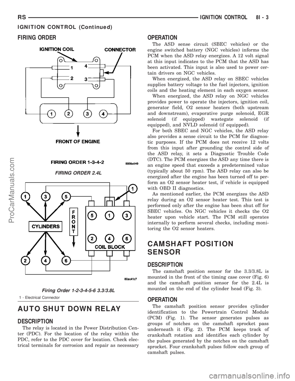
FIRING ORDER
AUTO SHUT DOWN RELAY
DESCRIPTION
The relay is located in the Power Distribution Cen-
ter (PDC). For the location of the relay within the
PDC, refer to the PDC cover for location. Check elec-
trical terminals for corrosion and repair as necessary
OPERATION
The ASD sense circuit (SBEC vehicles) or the
engine switched battery (NGC vehicles) informs the
PCM when the ASD relay energizes. A 12 volt signal
at this input indicates to the PCM that the ASD has
been activated. This input is also used to power cer-
tain drivers on NGC vehicles.
When energized, the ASD relay on SBEC vehicles
supplies battery voltage to the fuel injectors, ignition
coils and the heating element in each oxygen sensor.
When energized, the ASD relay on NGC vehicles
provides power to operate the injectors, ignition coil,
generator field, O2 sensor heaters (both upstream
and downstream), evaporative purge solenoid, EGR
solenoid (if equipped) wastegate solenoid (if
equipped), and NVLD solenoid (if equipped).
For both SBEC and NGC vehicles, the ASD relay
also provides a sense circuit to the PCM for diagnos-
tic purposes. If the PCM does not receive 12 volts
from this input after grounding the control side of
the ASD relay, it sets a Diagnostic Trouble Code
(DTC). The PCM energizes the ASD any time there is
an engine speed that exceeds a predetermined value
(typically about 50 rpm). The ASD relay can also be
energized after the engine has been turned off to per-
form an O2 sensor heater test, if vehicle is equipped
with OBD II diagnostics.
As mentioned earlier, the PCM energizes the ASD
relay during an O2 sensor heater test. This test is
performed only after the engine has been shut off for
SBEC vehicles. On NGC vehicles it checks the O2
heater upon vehicle start. The PCM still operates
internally to perform several checks, including moni-
toring the O2 sensor heaters.
CAMSHAFT POSITION
SENSOR
DESCRIPTION
The camshaft position sensor for the 3.3/3.8L is
mounted in the front of the timing case cover (Fig. 6)
and the camshaft position sensor for the 2.4L is
mounted on the end of the cylinder head (Fig. 3).
OPERATION
The camshaft position sensor provides cylinder
identification to the Powertrain Control Module
(PCM) (Fig. 1). The sensor generates pulses as
groups of notches on the camshaft sprocket pass
underneath it (Fig. 2). The PCM keeps track of
crankshaft rotation and identifies each cylinder by
the pulses generated by the notches on the camshaft
sprocket. Four crankshaft pulses follow each group of
camshaft pulses.
FIRING ORDER 2.4L
Firing Order 1-2-3-4-5-6 3.3/3.8L
1 - Electrical Connector
RSIGNITION CONTROL8I-3
IGNITION CONTROL (Continued)
ProCarManuals.com
Page 399 of 2177

When the PCM receives 2 cam pulses followed by
the long flat spot on the camshaft sprocket, it knows
that the crankshaft timing marks for cylinder 1 are
next (on driveplate). When the PCM receives one
camshaft pulse after the long flat spot on the
sprocket, cylinder number 2 crankshaft timing marks
are next. After 3 camshaft pulses, the PCM knows
cylinder 4 crankshaft timing marks follow. One cam-
shaft pulse after the 3 pulses indicates cylinder 5.
The 2 camshaft pulses after cylinder 5 signals cylin-
der 6 (Fig. 2). The PCM can synchronize on cylinders
1or4.
When metal aligns with the sensor, voltage goes
low (less than 0.3 volts). When a notch aligns with
the sensor, voltage switches high (5.0 volts). As a
group of notches pass under the sensor, the voltage
switches from low (metal) to high (notch) then back
to low. The number of notches determine the amount
of pulses. If available, an oscilloscope can display the
square wave patterns of each timing event.
Top Dead Center (TDC) does not occur when
notches on the camshaft sprocket pass below the sen-
sor. TDC occurs after the camshaft pulse (or pulses)
and after the 4 crankshaft pulses associated with the
particular cylinder. The arrows and cylinder call outs
on (Fig. 2) represent which cylinder the flat spot and
notches identify, they do not indicate TDC position.
REMOVAL
REMOVAL - 2.4L
The camshaft position sensor is mounted to the
rear of the cylinder head.
(1) Remove the negative battery cable.(2) Disconnect electrical connectors from the cam-
shaft position sensor (Fig. 3).
Fig. 1 Camshaft Position Sensor
1 - ELECTRICAL CONNECTOR
2 - O-RING
3 - PAPER SPACER
Fig. 2 Camshaft Sprocket
1 - CAMSHAFT SPROCKET
2 - CYL #6
3 - CYL #5
4 - CYL #4
5 - CYL #3
6 - CYL #2
7 - CYL #1
Fig. 3 EGR/CAM SENSOR 2.4L
8I - 4 IGNITION CONTROLRS
CAMSHAFT POSITION SENSOR (Continued)
ProCarManuals.com
Page 1181 of 2177
REMOVAL - CYLINDER HEAD OFF........32
INSPECTION..........................32
INSTALLATION
INSTALLATION - CYLINDER HEAD ON.....33
INSTALLATION - CYLINDER HEAD OFF....33
HYDRAULIC LASH ADJUSTERS
DIAGNOSIS AND TESTING - HYDRAULIC
LASH ADJUSTER NOISE DIAGNOSIS......34
REMOVAL.............................34
INSTALLATION.........................34
ROCKER ARMS
REMOVAL.............................34
INSPECTION..........................35
INSTALLATION.........................35
ENGINE BLOCK
DESCRIPTION.........................35
STANDARD PROCEDURE - CYLINDER BORE
HONING............................35
CLEANING............................36
INSPECTION..........................36
CRANKSHAFT
STANDARD PROCEDURE - CRANKSHAFT
ENDPLAY ...........................36
REMOVAL - CRANKSHAFT................37
INSPECTION..........................37
INSTALLATION - CRANKSHAFT............38
CRANKSHAFT OIL SEAL - FRONT
REMOVAL.............................40
INSTALLATION.........................40
CRANKSHAFT OIL SEAL - REAR
REMOVAL.............................41
INSTALLATION.........................42
PISTON & CONNECTING ROD
DESCRIPTION.........................42
STANDARD PROCEDURE - PISTON TO
CYLINDER BORE FITTING..............42
REMOVAL.............................43
INSTALLATION.........................44
CONNECTING ROD BEARINGS
STANDARD PROCEDURE
CONNECTING ROD - FITTING...........45
PISTON RINGS
STANDARD PROCEDURE
PISTON RING - FITTING................45
REMOVAL.............................46
INSTALLATION.........................46
VIBRATION DAMPER
REMOVAL.............................47
INSTALLATION.........................47
STRUCTURAL COLLAR
REMOVAL.............................47
INSTALLATION.........................48
ENGINE MOUNTING
DESCRIPTION.........................48
FRONT MOUNT
REMOVAL.............................49
INSTALLATION.........................49LEFT MOUNT
REMOVAL.............................49
INSTALLATION.........................50
REAR MOUNT
REMOVAL.............................50
INSTALLATION.........................50
RIGHT MOUNT
REMOVAL.............................51
INSTALLATION.........................51
LUBRICATION
DESCRIPTION.........................52
OPERATION...........................52
DIAGNOSIS AND TESTING - CHECKING
ENGINE OIL PRESSURE................52
OIL
STANDARD PROCEDURE
ENGINE OIL LEVEL CHECK.............53
STANDARD PROCEDURE - ENGINE OIL
AND FILTER CHANGE..................53
OIL FILTER
DESCRIPTION.........................53
REMOVAL.............................53
INSTALLATION.........................53
OIL PAN
REMOVAL.............................54
INSTALLATION.........................54
OIL PRESSURE SWITCH
REMOVAL.............................54
INSTALLATION.........................54
OIL PUMP
REMOVAL.............................55
DISASSEMBLY.........................55
CLEANING............................56
INSPECTION..........................56
ASSEMBLY............................56
INSTALLATION.........................57
INTAKE MANIFOLD
DESCRIPTION.........................58
DIAGNOSIS AND TESTING - INTAKE
MANIFOLD LEAKS.....................58
INTAKE MANIFOLD - UPPER
REMOVAL.............................58
INSPECTION..........................59
INSTALLATION.........................59
INTAKE MANIFOLD - LOWER
REMOVAL.............................60
INSPECTION..........................60
INSTALLATION.........................60
EXHAUST MANIFOLD
REMOVAL.............................61
CLEANING............................61
INSPECTION..........................61
INSTALLATION.........................61
TIMING BELT COVER(S)
REMOVAL.............................61
INSTALLATION.........................62
9 - 2 ENGINE 2.4LRS
ProCarManuals.com
Page 1182 of 2177
TIMING BELT AND SPROCKET(S)
REMOVAL
REMOVAL - TIMING BELT...............63
REMOVAL - CAMSHAFT SPROCKETS.....64
REMOVAL - CRANKSHAFT SPROCKET....64
CLEANING............................64
INSTALLATION
INSTALLATION - CRANKSHAFT SPROCKET . 65
INSTALLATION - CAMSHAFT SPROCKETS . . 65INSTALLATION - TIMING BELT...........65
TIMING BELT TENSIONER & PULLEY
REMOVAL.............................68
INSTALLATION.........................69
BALANCE SHAFTS AND CARRIER ASSEMBLY
DESCRIPTION.........................69
OPERATION...........................69
REMOVAL.............................69
INSTALLATION.........................72
ENGINE 2.4L
DESCRIPTION
The 2.4 Liter (148 cu. in.) in-line four cylinder
engine is a double over head camshaft with hydraulic
lash adjusters and four valve per cylinder design.
The engine is free-wheeling; meaning it has provi-
sions for piston-to-valve clearance. However valve-to-
valve interference can occur, if camshafts are rotated
independently.
The cylinders are numbered from front of the
engine to the rear. The firing order is 1±3±4±2.
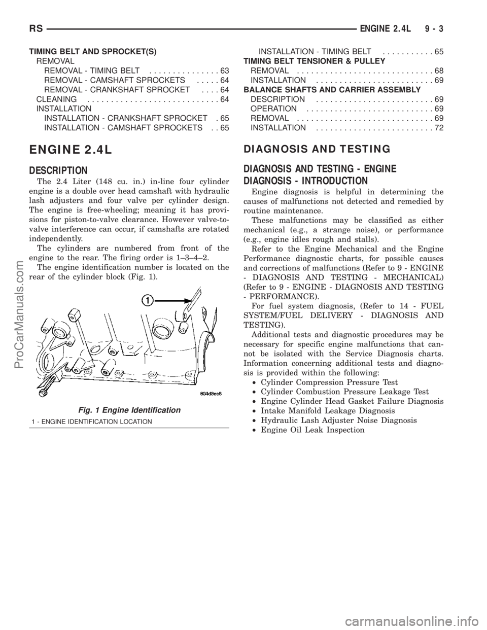
The engine identification number is located on the
rear of the cylinder block (Fig. 1).
DIAGNOSIS AND TESTING
DIAGNOSIS AND TESTING - ENGINE
DIAGNOSIS - INTRODUCTION
Engine diagnosis is helpful in determining the
causes of malfunctions not detected and remedied by
routine maintenance.
These malfunctions may be classified as either
mechanical (e.g., a strange noise), or performance
(e.g., engine idles rough and stalls).
Refer to the Engine Mechanical and the Engine
Performance diagnostic charts, for possible causes
and corrections of malfunctions (Refer to 9 - ENGINE
- DIAGNOSIS AND TESTING - MECHANICAL)
(Refer to 9 - ENGINE - DIAGNOSIS AND TESTING
- PERFORMANCE).
For fuel system diagnosis, (Refer to 14 - FUEL
SYSTEM/FUEL DELIVERY - DIAGNOSIS AND
TESTING).
Additional tests and diagnostic procedures may be
necessary for specific engine malfunctions that can-
not be isolated with the Service Diagnosis charts.
Information concerning additional tests and diagno-
sis is provided within the following:
²Cylinder Compression Pressure Test
²Cylinder Combustion Pressure Leakage Test
²Engine Cylinder Head Gasket Failure Diagnosis
²Intake Manifold Leakage Diagnosis
²Hydraulic Lash Adjuster Noise Diagnosis
²Engine Oil Leak Inspection
Fig. 1 Engine Identification
1 - ENGINE IDENTIFICATION LOCATION
RSENGINE 2.4L9-3
ProCarManuals.com
Page 1197 of 2177
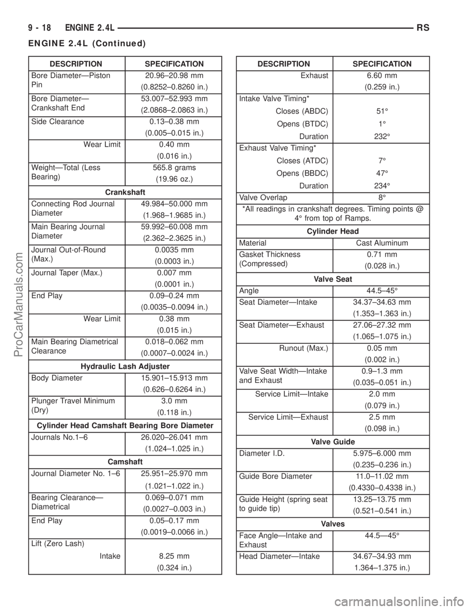
DESCRIPTION SPECIFICATION
Bore DiameterÐPiston
Pin20.96±20.98 mm
(0.8252±0.8260 in.)
Bore DiameterÐ
Crankshaft End53.007±52.993 mm
(2.0868±2.0863 in.)
Side Clearance 0.13±0.38 mm
(0.005±0.015 in.)
Wear Limit 0.40 mm
(0.016 in.)
WeightÐTotal (Less
Bearing)565.8 grams
(19.96 oz.)
Crankshaft
Connecting Rod Journal
Diameter49.984±50.000 mm
(1.968±1.9685 in.)
Main Bearing Journal
Diameter59.992±60.008 mm
(2.362±2.3625 in.)
Journal Out-of-Round
(Max.)0.0035 mm
(0.0003 in.)
Journal Taper (Max.) 0.007 mm
(0.0001 in.)
End Play 0.09±0.24 mm
(0.0035±0.0094 in.)
Wear Limit 0.38 mm
(0.015 in.)
Main Bearing Diametrical
Clearance0.018±0.062 mm
(0.0007±0.0024 in.)
Hydraulic Lash Adjuster
Body Diameter 15.901±15.913 mm
(0.626±0.6264 in.)
Plunger Travel Minimum
(Dry)3.0 mm
(0.118 in.)
Cylinder Head Camshaft Bearing Bore Diameter
Journals No.1±6 26.020±26.041 mm
(1.024±1.025 in.)
Camshaft
Journal Diameter No. 1±6 25.951±25.970 mm
(1.021±1.022 in.)
Bearing ClearanceÐ
Diametrical0.069±0.071 mm
(0.0027±0.003 in.)
End Play 0.05±0.17 mm
(0.0019±0.0066 in.)
Lift (Zero Lash)
Intake 8.25 mm
(0.324 in.)DESCRIPTION SPECIFICATION
Exhaust 6.60 mm
(0.259 in.)
Intake Valve Timing*
Closes (ABDC) 51É
Opens (BTDC) 1É
Duration 232É
Exhaust Valve Timing*
Closes (ATDC) 7É
Opens (BBDC) 47É
Duration 234É
Valve Overlap 8É
*All readings in crankshaft degrees. Timing points @
4É from top of Ramps.
Cylinder Head
Material Cast Aluminum
Gasket Thickness
(Compressed)0.71 mm
(0.028 in.)
Valve Seat
Angle 44.5±45É
Seat DiameterÐIntake 34.37±34.63 mm
(1.353±1.363 in.)
Seat DiameterÐExhaust 27.06±27.32 mm
(1.065±1.075 in.)
Runout (Max.) 0.05 mm
(0.002 in.)
Valve Seat WidthÐIntake
and Exhaust0.9±1.3 mm
(0.035±0.051 in.)
Service LimitÐIntake 2.0 mm
(0.079 in.)
Service LimitÐExhaust 2.5 mm
(0.098 in.)
Valve Guide
Diameter I.D. 5.975±6.000 mm
(0.235±0.236 in.)
Guide Bore Diameter 11.0±11.02 mm
(0.4330±0.4338 in.)
Guide Height (spring seat
to guide tip)13.25±13.75 mm
(0.521±0.541 in.)
Valves
Face AngleÐIntake and
Exhaust44.5Ð45É
Head DiameterÐIntake 34.67±34.93 mm
1.364±1.375 in.)
9 - 18 ENGINE 2.4LRS
ENGINE 2.4L (Continued)
ProCarManuals.com
Page 1199 of 2177

SPECIFICATIONS - TORQUE
DESCRIPTION N´mFt.
Lbs.In.
Lbs.
Balance Shaft Carrier to
BlockÐBolts54 40 Ð
Balance Shaft Gear
CoverÐDouble Ended
Fastener12 Ð 105
Balance Shaft SprocketÐ
Bolt28 Ð 250
Balance Shaft Chain
TensionerÐBolts12 Ð 105
Balance Shaft Carrier
CoverÐBolts12 Ð 105
Camshaft SprocketÐBolt 101 75 Ð
Connecting Rod
CapÐBolts27 +
1¤4
turn20
+1¤4
turnÐ
Crankshaft Main Bearing
Cap/Bedplate
ÐM8 Bolts 28 250
ÐM11 Bolts 41 +
1¤4
Turn30
+1¤4
TurnÐ
Crankshaft Damper 136 100 Ð
Cylinder HeadÐBolts (Refer to 9 - ENGINE/
CYLINDER HEAD -
INSTALLATION)
Cylinder Head CoverÐ
Bolts12 Ð 105
Flex Plate to Crankshaft 95 70 Ð
Engine Mount Bracket
RightÐBolts61 45 Ð
Engine MountingÐBolts (Refer to 9 ENGINE/
ENGINE MOUNTING)
Exhaust Manifold to
Cylinder HeadÐBolts19 Ð 170
DESCRIPTION N´mFt.
Lbs.In.
Lbs.
Exhaust Manifold Heat
ShieldÐBolts12 Ð 105
Intake Manifold - Lower
ÐBolts28 Ð 250
Intake Manifold -
UpperÐBolts28 Ð 250
Oil Filter 12 Ð 105
Oil PanÐBolts 12 Ð 105
Oil Pan DrainÐPlug 28 20 Ð
Oil Pressure Switch 21 Ð 190
Oil Pump to BlockÐBolts 28 20 Ð
Oil Pump Cover
PlateÐBolts12 Ð 105
Oil Pump Pick-up
TubeÐBolt28 20 Ð
Oil Pump Relief
ValveÐCap41 30 Ð
Spark Plugs 18 13 Ð
Structural Collar (Refer to 9 - ENGINE/
ENGINE BLOCK/
STRUCTURAL COVER -
INSTALLATION)
Timing Belt Covers
- Front Covers to Rear
CoverÐBolts6Ð50
- Rear CoverÐM6 Bolts 12 Ð 105
ÐM8 Bolts 28 Ð 250
Timing Belt Idler Pulley 61 45 Ð
Timing Belt Tensioner
Lock Bolt25 Ð 220
Timing Belt Tensioner
AssemblyÐBolts61 45 Ð
9 - 20 ENGINE 2.4LRS
ENGINE 2.4L (Continued)
ProCarManuals.com
Page 1207 of 2177

(2) Hold each camshaft sprocket with Special Tool
6847 while removing center bolt (Fig. 20).
(3) Remove camshaft sprockets.
(4) Remove rear timing belt cover (Refer to 9 -
ENGINE/VALVE TIMING/TIMING BELT COVER(S)
- REMOVAL).
(5) Remove camshaft seal using Special Tool
C-4679A (Fig. 21).
CAUTION: Do not nick shaft seal surface or seal
bore.
INSTALLATION
(1) Shaft seal surface must be free of varnish, dirt
or nicks. Polish with 400 grit paper if necessary.(2) Install camshaft seals into cylinder head using
Special Tool MD-998306 until flush with head (Fig.
22).
(3) Install timing belt rear cover (Refer to 9 -
ENGINE/VALVE TIMING/TIMING BELT COVER(S)
- INSTALLATION).
(4) Install camshaft sprockets. Hold each sprocket
with Special Tool 6847 and tighten center bolt to 101
N´m (75 ft. lbs.) (Fig. 20).
(5) Install timing belt and front covers (Refer to 9 -
ENGINE/VALVE TIMING/TIMING BELT AND
SPROCKETS - INSTALLATION) (Refer to 9 -
ENGINE/VALVE TIMING/TIMING BELT COVER(S)
- INSTALLATION).
CAMSHAFT(S)
DESCRIPTION
Both camshafts have six bearing journal surfaces
and two cam lobes per cylinder (Fig. 23). Flanges at
the rear journals control camshaft end play. Provision
for a cam position sensor is located on the intake
camshaft on the rear of the cylinder head. A hydro-
dynamic oil seal is used for oil control at the front of
the camshaft.
OPERATION
The camshaft is driven by the crankshaft via drive
sprockets and belt. The camshaft has precisely
machined lobes to provide accurate valve timing and
duration.
Fig. 20 Camshaft Sprocket - Removal/Installation
1 - SPECIAL TOOL 6847
Fig. 21 Camshaft Oil Seal - Removal With C-4679A
1 - SPECIAL TOOL C-4679
Fig. 22 Camshaft Seal - Installation
1 - SPECIAL TOOL MD-998306
9 - 28 ENGINE 2.4LRS
CAMSHAFT OIL SEAL(S) (Continued)
ProCarManuals.com
Page 1216 of 2177

(4) Move crankshaft all the way to the front and
read the dial indicator. Refer to Engine Specifica-
tions.
REMOVAL - CRANKSHAFT
NOTE: Crankshaft can not be removed when engine
is in vehicle.
(1) Remove engine assembly from vehicle (Refer to
9 - ENGINE - REMOVAL).
(2) Separate transaxle from engine.
(3) Remove drive plate/flex plate.
(4) Remove crankshaft rear oil seal (Refer to 9 -
ENGINE/ENGINE BLOCK/CRANKSHAFT OIL
SEAL - REAR - REMOVAL).
(5) Mount engine on a suitable repair stand.
(6) Drain engine oil and remove oil filter.
(7) Remove crankshaft vibration damper (Refer to
9 - ENGINE/ENGINE BLOCK/VIBRATION
DAMPER - REMOVAL).
(8) Remove engine mount support bracket.
(9) Remove front timing belt covers (Refer to 9 -
ENGINE/VALVE TIMING/TIMING BELT COVER(S)
- REMOVAL).
(10) Remove the timing belt (Refer to 9 - ENGINE/
VALVE TIMING/TIMING BELT AND SPROCKETS -
REMOVAL).
(11) Remove the oil pan (Refer to 9 - ENGINE/LU-
BRICATION/OIL PAN - REMOVAL).
(12) Remove oil pump pick-up tube.
(13) Remove the crankshaft sprocket and oil pump
(Refer to 9 - ENGINE/LUBRICATION/OIL PUMP -
REMOVAL).
(14) Remove balance shafts and housing assembly
(Refer to 9 - ENGINE/VALVE TIMING/BALANCE
SHAFT - REMOVAL).
(15) Remove crankshaft position sensor.NOTE: If piston/connecting rod replacement is nec-
essary, remove cylinder head (Refer to 9 - ENGINE/
CYLINDER HEAD - REMOVAL).
(16) Using a permanent ink or paint marker, iden-
tify cylinder number on each connecting rod cap (Fig.
44).
CAUTION: DO NOT use a number stamp or a punch
to mark connecting rods. Damage to connecting
rod could occur.
(17) Remove all connecting rod bolts and caps.
Care should be taken not to damage the fracture rod
and cap surfaces.
NOTE: Do not reuse connecting rod bolts.
(18) Remove all bedplate bolts from the engine
block (Fig. 45).
(19) Using a mallet gently tap the bedplate loose
from the engine block dowel pins.
CAUTION: Do not pry up on one side of the bed-
plate. Damage may occur to cylinder block to bed-
plate alignment and thrust bearing.
(20) Bedplate should be removed evenly from the
cylinder block dowel pins to prevent damage to the
dowel pins and thrust bearing.
CAUTION: Use extreme care when handling crank-
shaft. Tone wheel damage can occur if crankshaft is
mis-handled.
(21) Lift out crankshaft from cylinder block. Do
not damage the main bearings or journals when
removing the crankshaft.
INSPECTION
For crankshaft specifications (Refer to 9 - ENGINE
- SPECIFICATIONS).
Fig. 43 CHECKING CRANKSHAFT END PLAY
Fig. 44 Identify Connecting Rod to Cylinder
RSENGINE 2.4L9-37
CRANKSHAFT (Continued)
ProCarManuals.com