tow CHRYSLER VOYAGER 2004 Service Manual
[x] Cancel search | Manufacturer: CHRYSLER, Model Year: 2004, Model line: VOYAGER, Model: CHRYSLER VOYAGER 2004Pages: 2585, PDF Size: 62.54 MB
Page 2278 of 2585

DESCRIPTION FIGURE
REAR SEAT REINFORCEMENTS - SHORT WHEEL BASE ONLY 100
CENTER CONSOLE REINFORCEMENT - SHORT WHEEL BASE ONLY 101
WHEELHOUSES - SHORT WHEEL BASE ONLY 102
FRONT SEAT CROSS MEMBER - SHORT WHEELBASE, ALL WHEEL DRIVE ONLY 103
FLOOR PAN SIDE RAIL - LONG WHEEL BASE ONLY 104
INNER BODY SIDE SILL REINFORCEMENTS 105
TOE BOARD CROSS MEMBER 106
FRONT SIDE RAIL - SHORT WHEEL BASE ONLY 107
DASH PANEL REINFORCEMENT 108
LOWER COWL PLENUM 109
UPPER COWL PLENUM SUPPORT 110
UPPER DASH PANEL 111
COWL SIDE PANELS 112
INSTRUMENT PANEL ATTACHMENT TAPPING PLATES 113
INSTRUMENT PANEL, DASH PANEL, ACM MODULE AND ACCELERATOR PEDAL 114
STRUT TOWER BRACKET AND COWL PLENUM 115
FRONT SIDE RAILS TO LOWER DASH PANEL 116
INNER BODY SIDE SILL TO LOWER DASH PANEL 117
FRONT HINGE TAPPING PLATE 118
FRONT HINGE PILLAR 119
INNER WINDSHIELD FRAME 120
WINDSHIELD FRAME 121
FENDER BRACKET 122
INNER B-PILLAR 123
STRIKER LATCH AND TAPPING PLATES 124
RIGHT REAR INNER QUARTER PANEL - LONG WHEEL BASE ONLY 125
RIGHT REAR INNER QUARTER PANEL/OUTER WHEELHOUSE - LONG WHEEL BASE
ONLY126
RIGHT REAR BODY SIDE APERTURE - LONG WHEEL BASE ONLY 127
STRIKER LATCH REINFORCEMENT - LONG WHEEL BASE ONLY 128
BELT TAPPING PLATE - LONG WHEEL BASE ONLY 129
C-PILLAR REINFORCEMENT - LONG WHEEL BASE ONLY 130
OUTER WHEELHOUSE - LONG WHEEL BASE ONLY 131
C AND D-PILLAR INNER REINFORCEMENTS - LONG WHEEL BASE ONLY 132
LEFT REAR INNER QUARTER PANEL - LONG WHEEL BASE ONLY 133
OUTER WHEELHOUSE EXTENSION - LONG WHEEL BASE ONLY 134
TAIL LAMP - LONG WHEEL BASE ONLY 135
SLIDING DOOR LATCH - LONG WHEEL BASE ONLY 136
ROOF BOW EXTENSION - LONG WHEEL BASE ONLY 137
RIGHT REAR INNER QUARTER PANEL - SHORT WHEEL BASE ONLY 138
LATCH REINFORCEMENT AND OUTER WHEELHOUSE - SHORT WHEEL BASE ONLY 139
D-PILLAR REINFORCEMENT - SHORT WHEEL BASE ONLY 140
RSBODY STRUCTURE23 - 167
WELD LOCATIONS (Continued)
Page 2280 of 2585
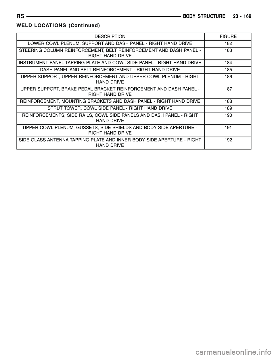
DESCRIPTION FIGURE
LOWER COWL PLENUM, SUPPORT AND DASH PANEL - RIGHT HAND DRIVE 182
STEERING COLUMN REINFORCEMENT, BELT REINFORCEMENT AND DASH PANEL -
RIGHT HAND DRIVE183
INSTRUMENT PANEL TAPPING PLATE AND COWL SIDE PANEL - RIGHT HAND DRIVE 184
DASH PANEL AND BELT REINFORCEMENT - RIGHT HAND DRIVE 185
UPPER SUPPORT, UPPER REINFORCEMENT AND UPPER COWL PLENUM - RIGHT
HAND DRIVE186
UPPER SUPPORT, BRAKE PEDAL BRACKET REINFORCEMENT AND DASH PANEL -
RIGHT HAND DRIVE187
REINFORCEMENT, MOUNTING BRACKETS AND DASH PANEL - RIGHT HAND DRIVE 188
STRUT TOWER, COWL SIDE PANEL - RIGHT HAND DRIVE 189
REINFORCEMENTS, SIDE RAILS, COWL SIDE PANELS AND DASH PANEL - RIGHT
HAND DRIVE190
UPPER COWL PLENUM, GUSSETS, SIDE SHIELDS AND BODY SIDE APERTURE -
RIGHT HAND DRIVE191
SIDE GLASS ANTENNA TAPPING PLATE AND INNER BODY SIDE APERTURE - RIGHT
HAND DRIVE192
RSBODY STRUCTURE23 - 169
WELD LOCATIONS (Continued)
Page 2283 of 2585
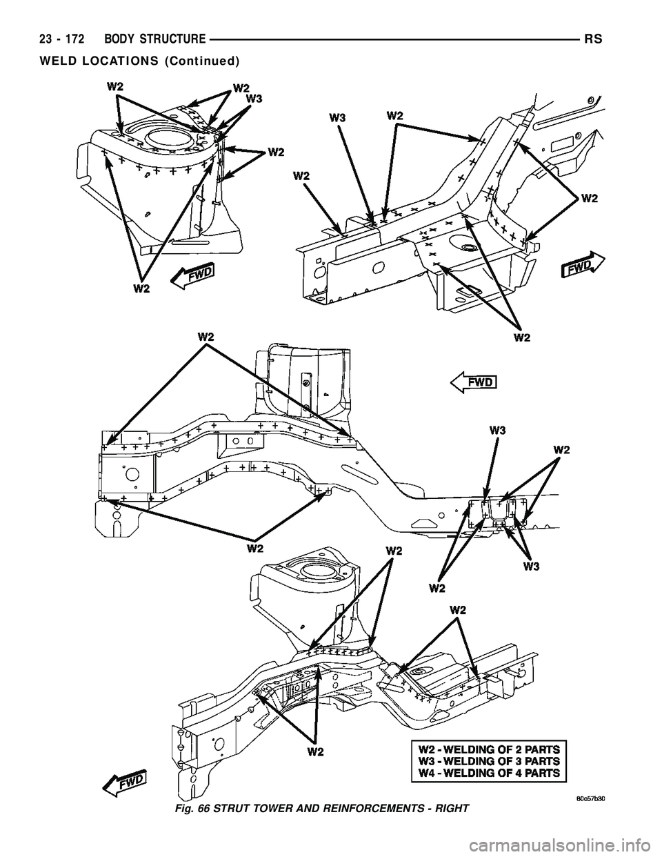
Fig. 66 STRUT TOWER AND REINFORCEMENTS - RIGHT
23 - 172 BODY STRUCTURERS
WELD LOCATIONS (Continued)
Page 2285 of 2585
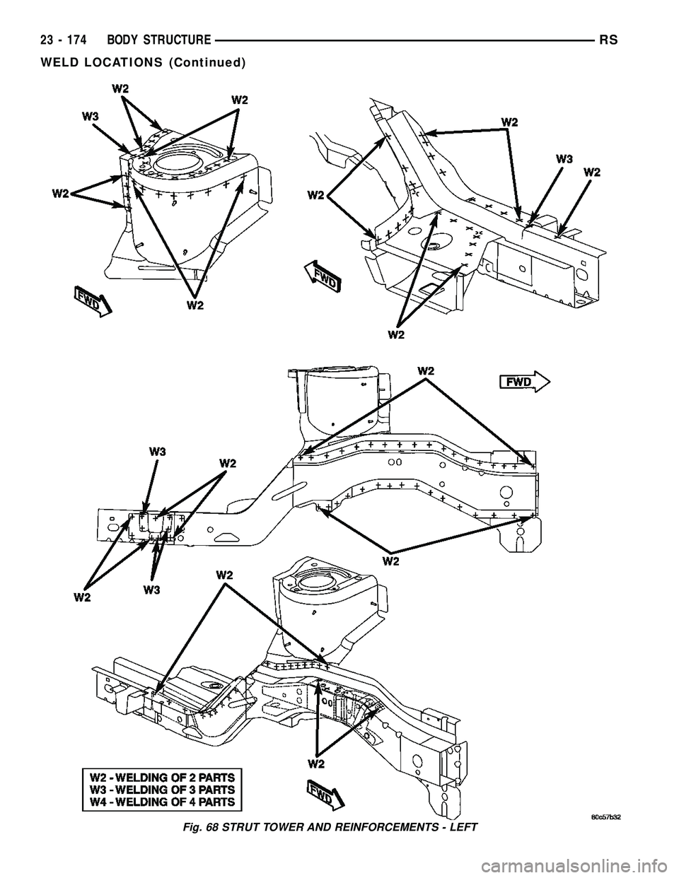
Fig. 68 STRUT TOWER AND REINFORCEMENTS - LEFT
23 - 174 BODY STRUCTURERS
WELD LOCATIONS (Continued)
Page 2303 of 2585

Fig. 86 ENGINE MOUNTING PLATE & TOW BRACKET
23 - 192 BODY STRUCTURERS
WELD LOCATIONS (Continued)
Page 2310 of 2585
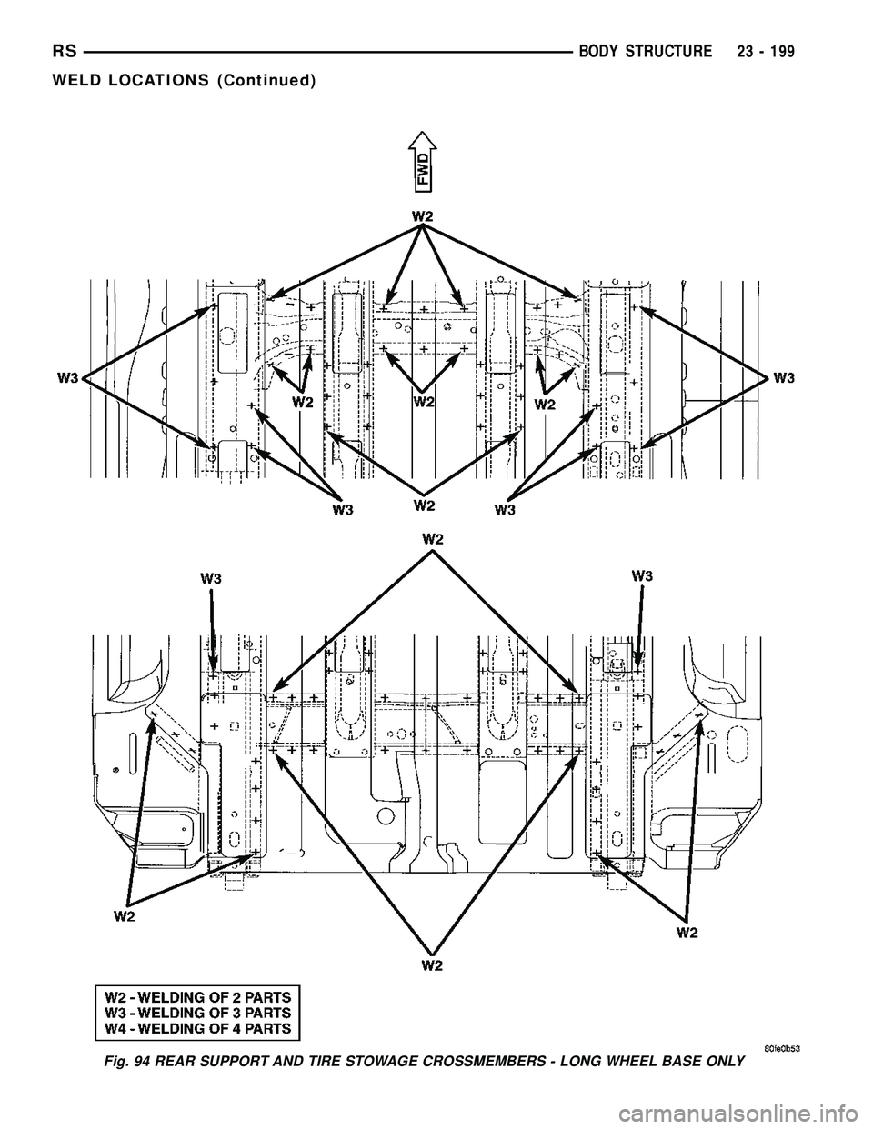
Fig. 94 REAR SUPPORT AND TIRE STOWAGE CROSSMEMBERS - LONG WHEEL BASE ONLY
RSBODY STRUCTURE23 - 199
WELD LOCATIONS (Continued)
Page 2313 of 2585
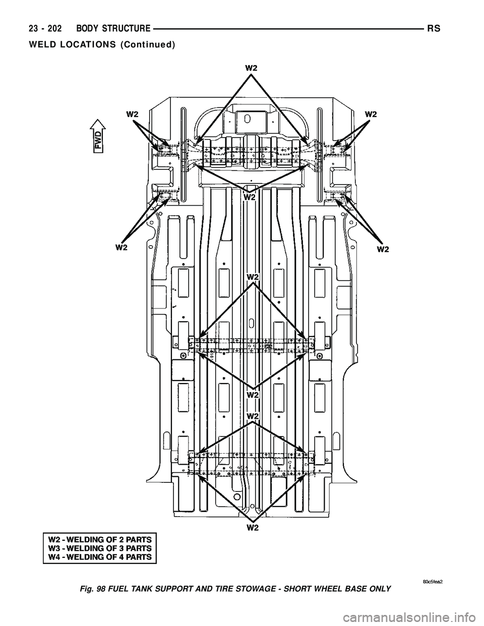
Fig. 98 FUEL TANK SUPPORT AND TIRE STOWAGE - SHORT WHEEL BASE ONLY
23 - 202 BODY STRUCTURERS
WELD LOCATIONS (Continued)
Page 2326 of 2585
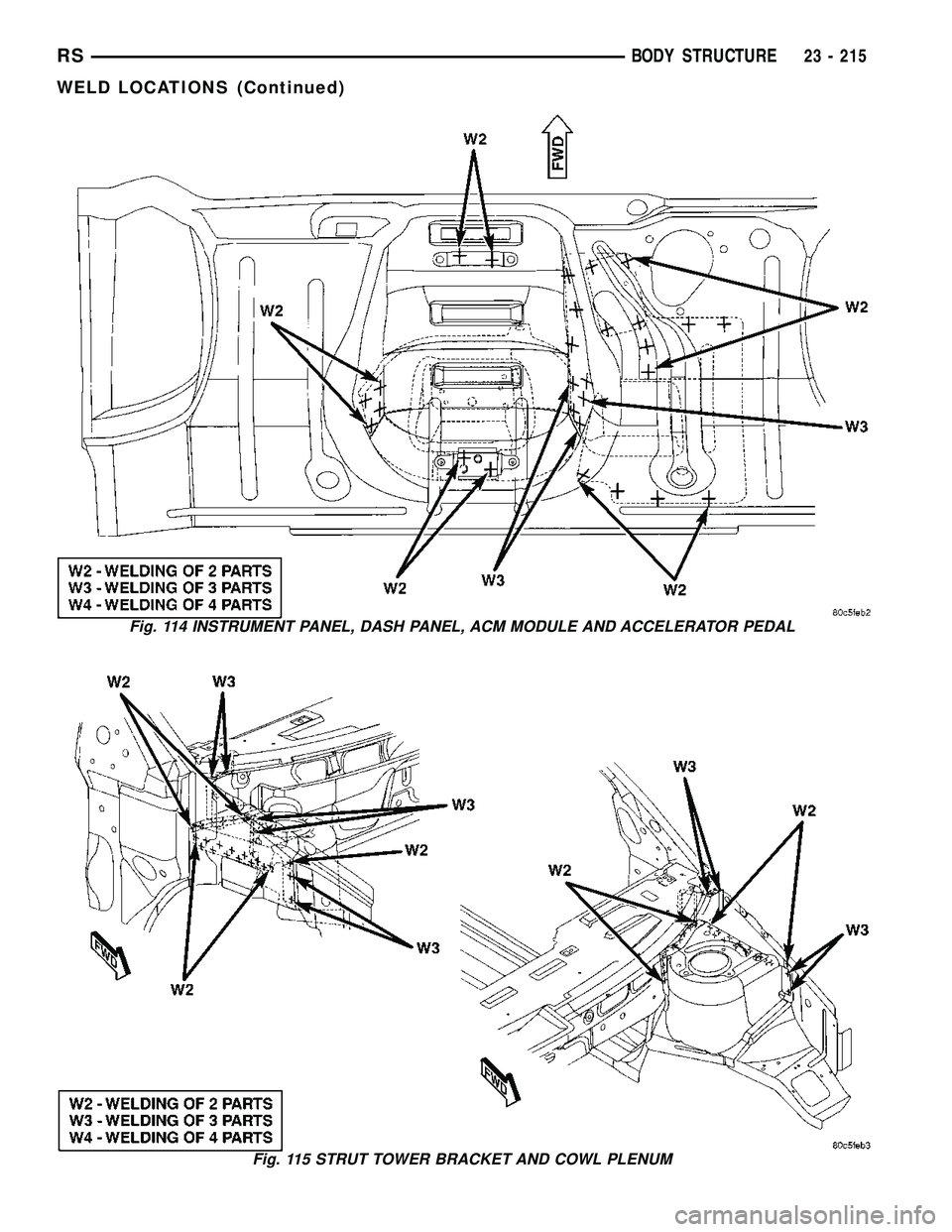
Fig. 114 INSTRUMENT PANEL, DASH PANEL, ACM MODULE AND ACCELERATOR PEDAL
Fig. 115 STRUT TOWER BRACKET AND COWL PLENUM
RSBODY STRUCTURE23 - 215
WELD LOCATIONS (Continued)
Page 2392 of 2585
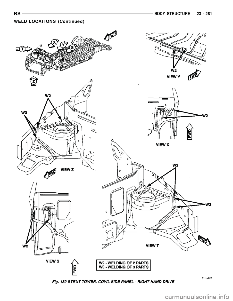
Fig. 189 STRUT TOWER, COWL SIDE PANEL - RIGHT HAND DRIVE
RSBODY STRUCTURE23 - 281
WELD LOCATIONS (Continued)
Page 2417 of 2585
erence signal and a sensor ground to the transducer,
then monitors the output voltage of the transducer
on a sensor return circuit to determine refrigerant
pressure. The PCM is programmed to respond to this
and other sensor inputs by controlling the operation
of the A/C compressor clutch and the radiator cooling
fan to help optimize air conditioning system perfor-
mance and to protect the system components from
damage. The A/C pressure transducer input to the
PCM will also prevent the A/C compressor clutch
from engaging when ambient temperatures are below
about 4.5É C (40É F) due to the pressure/temperature
relationship of the refrigerant. The Schrader-type
valve in the liquid line fitting permits the A/C pres-
sure transducer to be removed or installed without
disturbing the refrigerant in the system. The A/C
pressure transducer is diagnosed using a DRBIIIt
scan tool. Refer to Body Diagnostic Procedures.
DIAGNOSIS AND TESTING - A/C PRESSURE
TRANSDUCER
The A/C pressure transducer is tested using a
DRBIIItscan tool. Refer to the appropriate diagnos-
tic information. Before testing the A/C pressure
transducer, be certain that the transducer wire har-
ness connection is clean of corrosion and properly
connected. For the A/C to operate, an A/C pressure
transducer voltage reading between 0.451 and 4.519
volts is required. Voltages outside this range indicate
a low or high refrigerant system pressure condition
to the powertrain control module (PCM). The PCM is
programmed to respond to a low or high refrigerant
system pressure by suppressing operation of the A/C
compressor. Refer to the A/C Pressure Transducer
Voltage chart for the possible conditions indicated by
the transducer voltage reading.
A/C PRESSURE TRANSDUCER VOLTAGE
Voltage Possible Indication
0.0 1. No sensor supply voltage from
PCM.
2. Shorted sensor circuit.
3. Faulty transducer.
0.150 TO 0.450 1. Ambient temperature below 10É
C (50É F).
2. Low refrigerant system pressure.
0.451 TO 4.519 1. Normal refrigerant system
pressure.
4.520 TO 4.850 1. High refrigerant system pressure.
5.0 1. Open sensor circuit.
2. Faulty transducer.
REMOVAL
NOTE: Note: It is not necessary to discharge the
refrigerant system to replace the A/C pressure
transducer.
(1) Disconnect and isolate the battery negative
cable.
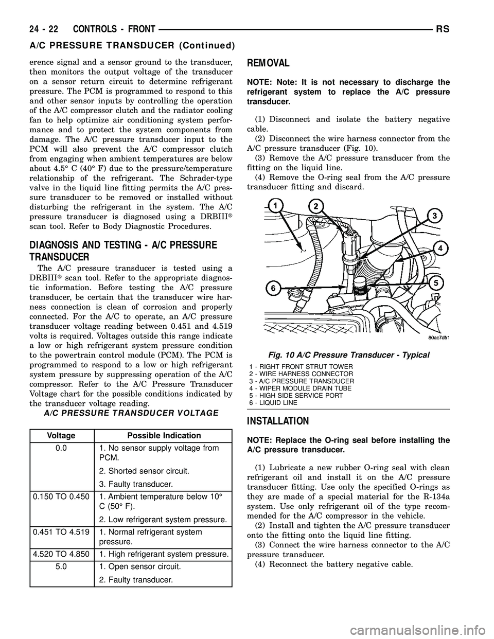
(2) Disconnect the wire harness connector from the
A/C pressure transducer (Fig. 10).
(3) Remove the A/C pressure transducer from the
fitting on the liquid line.
(4) Remove the O-ring seal from the A/C pressure
transducer fitting and discard.
INSTALLATION
NOTE: Replace the O-ring seal before installing the
A/C pressure transducer.
(1) Lubricate a new rubber O-ring seal with clean
refrigerant oil and install it on the A/C pressure
transducer fitting. Use only the specified O-rings as
they are made of a special material for the R-134a
system. Use only refrigerant oil of the type recom-
mended for the A/C compressor in the vehicle.
(2) Install and tighten the A/C pressure transducer
onto the fitting onto the liquid line fitting.
(3) Connect the wire harness connector to the A/C
pressure transducer.
(4) Reconnect the battery negative cable.
Fig. 10 A/C Pressure Transducer - Typical
1 - RIGHT FRONT STRUT TOWER
2 - WIRE HARNESS CONNECTOR
3 - A/C PRESSURE TRANSDUCER
4 - WIPER MODULE DRAIN TUBE
5 - HIGH SIDE SERVICE PORT
6 - LIQUID LINE
24 - 22 CONTROLS - FRONTRS
A/C PRESSURE TRANSDUCER (Continued)