CHRYSLER VOYAGER 2004 Service Manual
Manufacturer: CHRYSLER, Model Year: 2004, Model line: VOYAGER, Model: CHRYSLER VOYAGER 2004Pages: 2585, PDF Size: 62.54 MB
Page 1681 of 2585

(17) Raise vehicle on hoist.
(18) Remove selector cable from engine compart-
ment, then remove cable from passenger compart-
ment through opening in floor pan.
INSTALLATION
(1) From underneath vehicle, install gearshift
selector cable into passenger compartment through
floor pan hole. Install remainder of cable into posi-
tion in engine compartment.
(2) Lower vehicle.
(3) Install selector cable to mount bracket and
secure with retainer clip (Fig. 172).
(4) Install cable to transaxle selector lever (Fig.
172).
(5)2.4L Gas models goto Step 10. 2.5L TD
models:Install coolant recovery bottle bracket (Fig.
173).(6) Install coolant recovery bottle to bracket.
(7) Connect battery temperature sensor to battery
tray. Install battery tray into position (Fig. 174).
Fig. 172 Gearshift Cables at Transaxle
1 - SELECTOR CABLE
2 - CABLE RETAINER
3 - CABLE RETAINER
4 - CROSSOVER CABLE
5 - MOUNT BRACKET
Fig. 173 Coolant Recovery Bottle Bracket
1 - COOLANT RECOVERY BOTTLE BRACKET
2 - NUT
3 - MOUNT BRACKET
Fig. 174 Battery Tray
1 - BATTERY TRAY
21 - 84 T850 MANUAL TRANSAXLERS
GEARSHIFT CABLE - SELECTOR (Continued)
Page 1682 of 2585
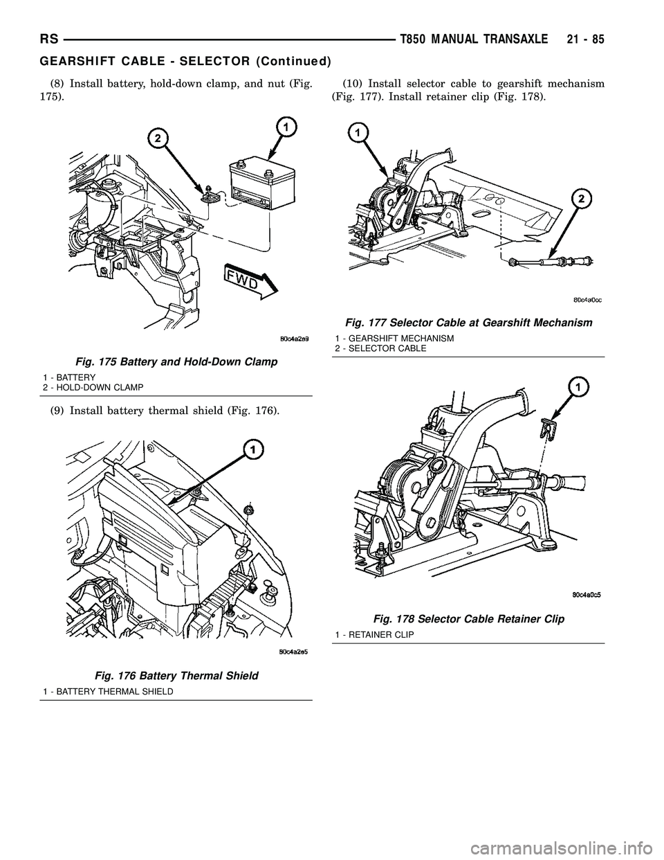
(8) Install battery, hold-down clamp, and nut (Fig.
175).
(9) Install battery thermal shield (Fig. 176).(10) Install selector cable to gearshift mechanism
(Fig. 177). Install retainer clip (Fig. 178).
Fig. 175 Battery and Hold-Down Clamp
1 - BATTERY
2 - HOLD-DOWN CLAMP
Fig. 176 Battery Thermal Shield
1 - BATTERY THERMAL SHIELD
Fig. 177 Selector Cable at Gearshift Mechanism
1 - GEARSHIFT MECHANISM
2 - SELECTOR CABLE
Fig. 178 Selector Cable Retainer Clip
1 - RETAINER CLIP
RST850 MANUAL TRANSAXLE21-85
GEARSHIFT CABLE - SELECTOR (Continued)
Page 1683 of 2585

(11) Install center console support bracket (Fig.
179). Torque support bracket-to-gearshift mechanism
screws to 12 N´m (108 in. lbs.).
(12) Install center console assembly (Fig. 180).
Install and torque center console-to-gearshift mecha-
nism screws to 5 N´m (45 in. lbs.).(13) Install cupholder plugs (Fig. 181).
(14) Install gearshift boot to console (Fig. 182).
Secure with three (3) retainer clips.
Fig. 179 Center Console Support Bracket
1 - BRACKET
2 - SCREW
3 - GEARSHIFT MECHANISM
Fig. 180 Center Console Removal/Installation (LHD
Shown Ð RHD Typical)
1 - CENTER CONSOLE
2 - SCREW (4)
3 - GEARSHIFT MECHANISM
Fig. 181 Cup Holder Plugs
1 - CUPHOLDER PLUG (2)
Fig. 182 Gearshift Boot Removal/Installation
1 - GEARSHIFT BOOT
2 - CENTER CONSOLE
21 - 86 T850 MANUAL TRANSAXLERS
GEARSHIFT CABLE - SELECTOR (Continued)
Page 1684 of 2585

(15) Install gearshift knob to gearshift lever (Fig.
183). Orient shift pattern1¤4-turn clockwise, push
down and rotate1¤4-turn counter-clockwise and
release. Secure boot to knob.
(16) Connect battery negative cable.
GEARSHIFT KNOB
REMOVAL
(1) Separate gearshift boot from base of knob.
(2) Remove gearshift knob by pushing down and
rotating
1¤4-turn clockwise (Fig. 184).
INSTALLATION
(1) Install gearshift knob pattern1¤4-turn clock-
wise, press down, and rotate1¤4-turn counter clock-
wise (Fig. 184).
(2) Secure gearshift boot to base of knob.
GEARSHIFT MECHANISM
REMOVAL
(1) Disconnect battery negative cable.
(2) Remove gearshift knob by pushing down and
rotating
1¤4turn clock-wise (Fig. 185).
Fig. 183 Gearshift Knob Removal/Installation
1 - GEARSHIFT KNOB
2 - GEARSHIFT LEVER
Fig. 184 Gearshift Knob Removal/Installation
1 - GEARSHIFT KNOB
2 - GEARSHIFT LEVER
Fig. 185 Gearshift Knob Removal/Installation
1 - GEARSHIFT KNOB
2 - GEARSHIFT LEVER
RST850 MANUAL TRANSAXLE21-87
GEARSHIFT CABLE - SELECTOR (Continued)
Page 1685 of 2585

(3) Remove gearshift boot from center console by
disengaging at three (3) retaining clips (Fig. 186).
(4) Apply park brake to allow park brake handle to
clear center console upon removal.
(5) Remove two (2) cupholder bottom plugs (Fig.
187).(6) Remove four (4) center console-to-gearshift
mechanism screws. Remove console assembly (Fig.
188).
(7) Remove center console support bracket (Fig.
189).
Fig. 186 Gearshift Boot Removal/Installation
1 - GEARSHIFT BOOT
2 - CENTER CONSOLE
Fig. 187 Cup Holder Plugs
1 - CUPHOLDER PLUG (2)
Fig. 188 Center Console Removal/Installation (LHD
Shown Ð RHD Typical)
1 - CENTER CONSOLE
2 - SCREW (4)
3 - GEARSHIFT MECHANISM
Fig. 189 Center Console Support Bracket
1 - BRACKET
2 - SCREW
3 - GEARSHIFT MECHANISM
21 - 88 T850 MANUAL TRANSAXLERS
GEARSHIFT MECHANISM (Continued)
Page 1686 of 2585
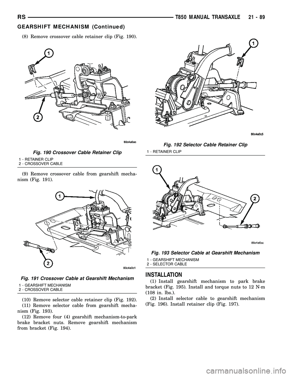
(8) Remove crossover cable retainer clip (Fig. 190).
(9) Remove crossover cable from gearshift mecha-
nism (Fig. 191).
(10) Remove selector cable retainer clip (Fig. 192).
(11) Remove selector cable from gearshift mecha-
nism (Fig. 193).
(12) Remove four (4) gearshift mechanism-to-park
brake bracket nuts. Remove gearshift mechanism
from bracket (Fig. 194).
INSTALLATION
(1) Install gearshift mechanism to park brake
bracket (Fig. 195). Install and torque nuts to 12 N´m
(108 in. lbs.).
(2) Install selector cable to gearshift mechanism
(Fig. 196). Install retainer clip (Fig. 197).
Fig. 190 Crossover Cable Retainer Clip
1 - RETAINER CLIP
2 - CROSSOVER CABLE
Fig. 191 Crossover Cable at Gearshift Mechanism
1 - GEARSHIFT MECHANISM
2 - CROSSOVER CABLE
Fig. 192 Selector Cable Retainer Clip
1 - RETAINER CLIP
Fig. 193 Selector Cable at Gearshift Mechanism
1 - GEARSHIFT MECHANISM
2 - SELECTOR CABLE
RST850 MANUAL TRANSAXLE21-89
GEARSHIFT MECHANISM (Continued)
Page 1687 of 2585
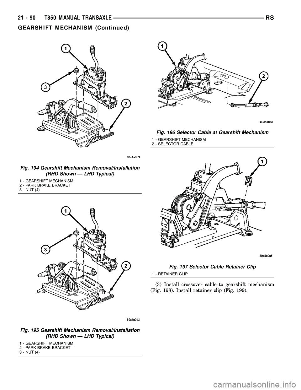
(3) Install crossover cable to gearshift mechanism
(Fig. 198). Install retainer clip (Fig. 199).
Fig. 194 Gearshift Mechanism Removal/Installation
(RHD Shown Ð LHD Typical)
1 - GEARSHIFT MECHANISM
2 - PARK BRAKE BRACKET
3 - NUT (4)
Fig. 195 Gearshift Mechanism Removal/Installation
(RHD Shown Ð LHD Typical)
1 - GEARSHIFT MECHANISM
2 - PARK BRAKE BRACKET
3 - NUT (4)
Fig. 196 Selector Cable at Gearshift Mechanism
1 - GEARSHIFT MECHANISM
2 - SELECTOR CABLE
Fig. 197 Selector Cable Retainer Clip
1 - RETAINER CLIP
21 - 90 T850 MANUAL TRANSAXLERS
GEARSHIFT MECHANISM (Continued)
Page 1688 of 2585
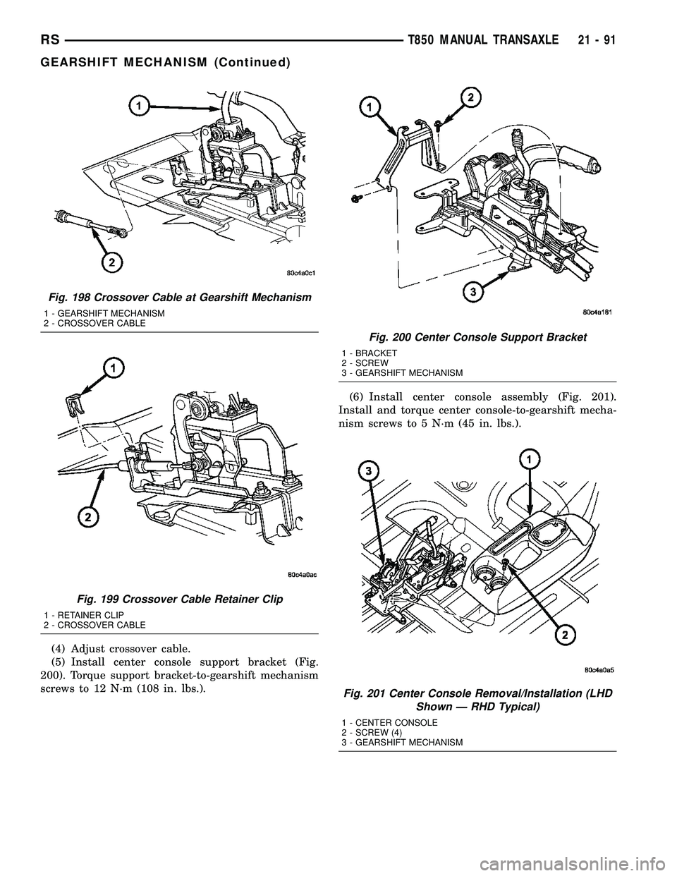
(4) Adjust crossover cable.
(5) Install center console support bracket (Fig.
200). Torque support bracket-to-gearshift mechanism
screws to 12 N´m (108 in. lbs.).(6) Install center console assembly (Fig. 201).
Install and torque center console-to-gearshift mecha-
nism screws to 5 N´m (45 in. lbs.).
Fig. 198 Crossover Cable at Gearshift Mechanism
1 - GEARSHIFT MECHANISM
2 - CROSSOVER CABLE
Fig. 199 Crossover Cable Retainer Clip
1 - RETAINER CLIP
2 - CROSSOVER CABLE
Fig. 200 Center Console Support Bracket
1 - BRACKET
2 - SCREW
3 - GEARSHIFT MECHANISM
Fig. 201 Center Console Removal/Installation (LHD
Shown Ð RHD Typical)
1 - CENTER CONSOLE
2 - SCREW (4)
3 - GEARSHIFT MECHANISM
RST850 MANUAL TRANSAXLE21-91
GEARSHIFT MECHANISM (Continued)
Page 1689 of 2585

(7) Install cupholder plugs (Fig. 202).
(8) Install gearshift boot to console (Fig. 203).
Secure with three (3) retainer clips.(9) Install gearshift knob to gearshift lever (Fig.
204). Orient shift pattern1¤4-turn clockwise, push
down and rotate1¤4-turn counter-clockwise and
release. Secure boot to knob.
(10) Connect battery negative cable.
Fig. 202 Cup Holder Plugs
1 - CUPHOLDER PLUG (2)
Fig. 203 Gearshift Boot Removal/Installation
1 - GEARSHIFT BOOT
2 - CENTER CONSOLE
Fig. 204 Gearshift Knob Removal/Installation
1 - GEARSHIFT KNOB
2 - GEARSHIFT LEVER
21 - 92 T850 MANUAL TRANSAXLERS
GEARSHIFT MECHANISM (Continued)
Page 1690 of 2585
INPUT SHAFT
DESCRIPTION
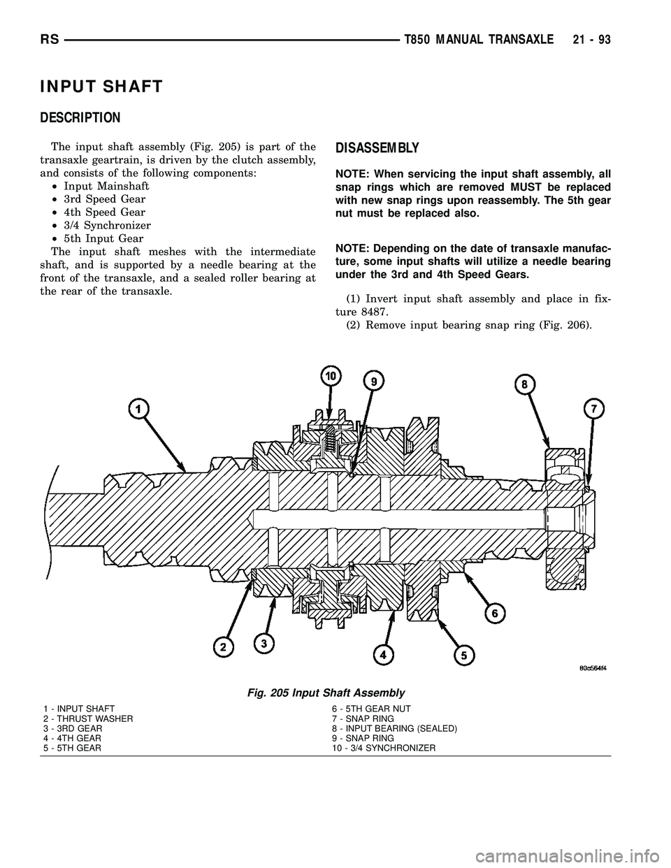
The input shaft assembly (Fig. 205) is part of the
transaxle geartrain, is driven by the clutch assembly,
and consists of the following components:
²Input Mainshaft
²3rd Speed Gear
²4th Speed Gear
²3/4 Synchronizer
²5th Input Gear
The input shaft meshes with the intermediate
shaft, and is supported by a needle bearing at the
front of the transaxle, and a sealed roller bearing at
the rear of the transaxle.DISASSEMBLY
NOTE: When servicing the input shaft assembly, all
snap rings which are removed MUST be replaced
with new snap rings upon reassembly. The 5th gear
nut must be replaced also.
NOTE: Depending on the date of transaxle manufac-
ture, some input shafts will utilize a needle bearing
under the 3rd and 4th Speed Gears.
(1) Invert input shaft assembly and place in fix-
ture 8487.
(2) Remove input bearing snap ring (Fig. 206).
Fig. 205 Input Shaft Assembly
1 - INPUT SHAFT 6 - 5TH GEAR NUT
2 - THRUST WASHER 7 - SNAP RING
3 - 3RD GEAR 8 - INPUT BEARING (SEALED)
4 - 4TH GEAR 9 - SNAP RING
5 - 5TH GEAR 10 - 3/4 SYNCHRONIZER
RST850 MANUAL TRANSAXLE21-93