engine CHRYSLER VOYAGER 2004 Service Manual
[x] Cancel search | Manufacturer: CHRYSLER, Model Year: 2004, Model line: VOYAGER, Model: CHRYSLER VOYAGER 2004Pages: 2585, PDF Size: 62.54 MB
Page 489 of 2585

CONDITION POSSIBLE CAUSE CORRECTION2. STARTING CIRCUIT
WIRING FAULTY. 2. REFER TO THE FEED CIRCUIT RESISTANCE TEST AND
THE FEED CIRCUIT TEST IN THIS SECTION. REPAIR AS
NECESSARY.
3. STARTER ASSEMBLY
FAULTY. 3. IF ALL OTHER STARTING SYSTEM COMPONENTS AND
CIRCUITS CHECK OK, REPLACE STARTER ASSEMBLY.
4. ENGINE SEIZED. 4. REFER TO THE ENGINE SECTION, FOR DIAGNOSTIC AND SERVICE PROCEDURES.
5. LOOSE
CONNECTION AT
BATTERY, PDC,
STARTER, OR ENGINE
GROUND. 5. INSPECT FOR LOOSE CONNECTIONS.
6. FAULTY TEETH ON
RING GEAR. 6. ROTATE FLYWHEEL 360É, AND INSPECT TEETH AND RING
GEAR REPLACED IF DAMAGED.
STARTER
ENGAGES,
SPINS OUT
BEFORE
ENGINE
STARTS. 1. BROKEN TEETH ON
STARTER RING GEAR.
1. REMOVE STARTER. INSPECT RING GEAR AND REPLACE
IF NECESSARY.
2. STARTER ASSEMBLY
FAULTY. 2. IF ALL OTHER STARTING SYSTEM COMPONENTS AND
CIRCUITS CHECK OK, REPLACE STARTER ASSEMBLY.
STARTER DOES
NOT
DISENGAGE. 1. STARTER
IMPROPERLY
INSTALLED. 1. INSTALL STARTER. TIGHTEN STARTER MOUNTING
HARDWARE TO CORRECT TORQUE SPECIFICATIONS.
2. STARTER RELAY
FAULTY. 2. REFER TO RELAY TEST, IN THIS SECTION. REPLACE
RELAY, IF NECESSARY.
3. IGNITION SWITCH
FAULTY. 3. REFER TO IGNITION SWITCH TEST, IN THE STEERING
SECTION. REPLACE SWITCH, IF NECESSARY.
4. STARTER ASSEMBLY
FAULTY. 4. IF ALL OTHER STARTING SYSTEM COMPONENTS AND
CIRCUITS CHECK OK, REPLACE STARTER ASSEMBLY.
5. FAULTY TEETH ON
RING GEAR. 5. ROTATE FLYWHEEL 360É, AND INSPECT TEETH AND RING
GEAR REPLACED IF DAMAGED.
DIAGNOSIS AND TESTING - CONTROL
CIRCUIT TEST
The starter control circuit has:
²
Starter motor with integral solenoid
² Starter relay
² Transmission range sensor, or Park/Neutral
Position switch with automatic transmissions ² Ignition switch
² Battery
² All related wiring and connections
² Powertrain Control Module (PCM)
CAUTION: Before performing any starter tests, the
ignition and fuel systems must be disabled. ²
To disable ignition and fuel systems, disconnect
the Automatic Shutdown Relay (ASD). The ASD relay
is located in the Power Distribution Center (PDC).
Refer to the PDC cover for the proper relay location.
STARTER SOLENOID
WARNING: CHECK TO ENSURE THAT THE TRANS-
MISSION IS IN THE PARK POSITION WITH THE
PARKING BRAKE APPLIED. THIS MAY RESULT IN
PERSONAL INJURY OR DEATH.
(1) Verify battery condition. Battery must be in
good condition with a full charge before performing
any starter tests. Refer to Battery Tests.
8Fs - 32 STARTINGRS
STARTING (Continued)
Page 490 of 2585
(2) Perform Starter Solenoid test BEFORE per-
forming the starter relay test. (3) Perform a visual inspection of the starter/
starter solenoid for corrosion, loose connections or
faulty wiring. (4) Locate and remove the starter relay from the
Power Distribution Center (PDC). Refer to the PDC
label for relay identification and location. (5) Connect a remote starter switch or a jumper
wire between the remote battery positive post and
terminal 87 of the starter relay connector. (a) If engine cranks, starter/starter solenoid is
good. Go to the Starter Relay Test. (b) If engine does not crank or solenoid chatters,
check wiring and connectors from starter relay to
starter solenoid and from the battery positive ter-
minal to starter post for loose or corroded connec-
tions. Particularly at starter terminals. (c) Repeat test. If engine still fails to crank prop-
erly, trouble is within starter or starter mounted
solenoid, and replace starter. Inspect the ring gear
teeth.
STARTER RELAY
WARNING: CHECK TO ENSURE THAT THE TRANS-
MISSION IS IN THE PARK/NEUTRAL POSITION
WITH THE PARKING BRAKE APPLIED. THIS MAY
RESULT IN PERSONAL INJURY OR DEATH.
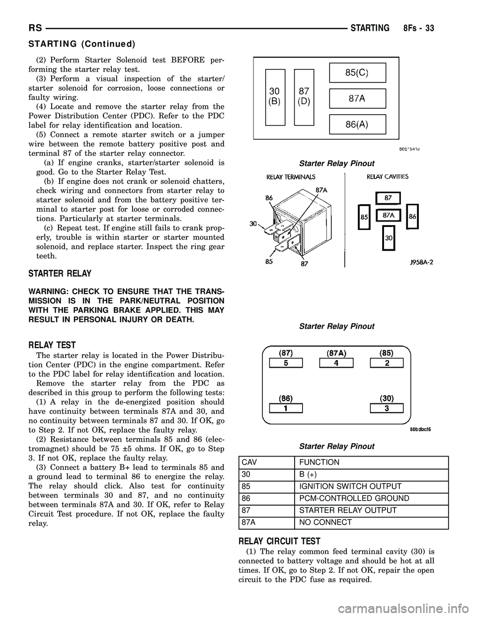
RELAY TEST
The starter relay is located in the Power Distribu-
tion Center (PDC) in the engine compartment. Refer
to the PDC label for relay identification and location. Remove the starter relay from the PDC as
described in this group to perform the following tests: (1) A relay in the de-energized position should
have continuity between terminals 87A and 30, and
no continuity between terminals 87 and 30. If OK, go
to Step 2. If not OK, replace the faulty relay. (2) Resistance between terminals 85 and 86 (elec-
tromagnet) should be 75 5 ohms. If OK, go to Step
3. If not OK, replace the faulty relay. (3) Connect a battery B+ lead to terminals 85 and
a ground lead to terminal 86 to energize the relay.
The relay should click. Also test for continuity
between terminals 30 and 87, and no continuity
between terminals 87A and 30. If OK, refer to Relay
Circuit Test procedure. If not OK, replace the faulty
relay.
CAV FUNCTION
30 B (+)
85 IGNITION SWITCH OUTPUT
86 PCM-CONTROLLED GROUND
87 STARTER RELAY OUTPUT
87A NO CONNECT
RELAY CIRCUIT TEST
(1) The relay common feed terminal cavity (30) is
connected to battery voltage and should be hot at all
times. If OK, go to Step 2. If not OK, repair the open
circuit to the PDC fuse as required.
Starter Relay Pinout
Starter Relay Pinout
Starter Relay Pinout
RS STARTING8Fs-33
STARTING (Continued)
Page 491 of 2585

(2) The relay normally closed terminal (87A) is
connected to terminal 30 in the de-energized position,
but is not used for this application. Go to Step 3. (3) The relay normally open terminal (87) is con-
nected to the common feed terminal (30) in the ener-
gized position. This terminal supplies battery voltage
to the starter solenoid field coils. There should be
continuity between the cavity for relay terminal 87
and the starter solenoid terminal at all times. If OK,
go to Step 4. If not OK, repair the open circuit to the
starter solenoid as required. (4) The coil battery terminal (85) is connected to
the electromagnet in the relay. It is energized when
the ignition switch is held in the Start position and
the clutch pedal is depressed (manual trans). Check
for battery voltage at the cavity for relay terminal 86
with the ignition switch in the Start position and the
clutch pedal is depressed (manual trans), and no
voltage when the ignition switch is released to the
On position. If OK, go to Step 5. If not OK, check for
an open or short circuit to the ignition switch and
repair, if required. If the circuit to the ignition switch
is OK, see the Ignition Switch Test procedure in this
group. (5) The coil ground terminal (86) is connected to
the electromagnet in the relay. It is grounded by the
PCM if the conditions are right to start the car. For
automatic trans. cars the PCM must see Park Neu-
tral switch low and near zero engine speed (rpm).
For manual trans. cars the PCM only needs to see
near zero engine speed (rpm) and low clutch inter-
lock input and see near zero engine speed (rpm). To
diagnose the Park Neutral switch of the trans range
sensor refer to the transaxle section. Check for conti-
nuity to ground while the ignition switch is in the
start position and if equipped the clutch pedal
depressed. If not OK and the vehicle has an auto-
matic trans. verify Park Neutral switch operation. If
that checks OK check for continuity between PCM
and the terminal 86. Repair open circuit as required.
Also check the clutch interlock switch operation if
equipped with a manual transmission. If OK, the
PCM may be defective.
SAFETY SWITCHES
For diagnostics of the Transmission Range Sensor,
refer to the Transaxle section for more information. If equipped with Clutch Interlock/Upstop Switch,
refer to Diagnosis and Testing in the Clutch section.
IGNITION SWITCH
After testing starter solenoid and relay, test igni-
tion switch and wiring. Refer to the Ignition Section
or Wiring Diagrams for more information. Check all
wiring for opens or shorts, and all connectors for
being loose or corroded.
BATTERY
For battery diagnosis and testing, refer to the Bat-
tery section for procedures.
ALL RELATED WIRING AND CONNECTORS
Refer to Wiring Diagrams for more information.
DIAGNOSIS AND TESTING - FEED CIRCUIT
RESISTANCE TEST
Before proceeding with this operation, review Diag-
nostic Preparation and Starter Feed Circuit Tests.
The following operation will require a voltmeter,
accurate to 1/10 of a volt.
CAUTION: Ignition and Fuel systems must be dis-
abled to prevent engine start while performing the
following tests.
(1) To disable the Ignition and Fuel systems, dis-
connect the Automatic Shutdown Relay (ASD). The
ASD relay is located in the Power Distribution Cen-
ter (PDC). Refer to the PDC cover for proper relay
location. (2) Gain access to battery terminals.
(3) With all wiring harnesses and components
properly connected, perform the following: (a) Connect the negative lead of the voltmeter to
the battery negative post, and positive lead to the
battery negative cable clamp. Rotate and hold the
ignition switch in the START position. Observe the
voltmeter. If voltage is detected, correct poor con-
tact between cable clamp and post. (b) Connect positive lead of the voltmeter to the
battery positive post, and negative lead to the bat-
tery positive cable clamp. Rotate and hold the igni-
tion switch key in the START position. Observe the
voltmeter. If voltage is detected, correct poor con-
tact between the cable clamp and post. (c) Connect negative lead of voltmeter to battery
negative terminal, and positive lead to engine
block near the battery cable attaching point.
Rotate and hold the ignition switch in the START
position. If voltage reads above 0.2 volt, correct
poor contact at ground cable attaching point. If
voltage reading is still above 0.2 volt after correct-
ing poor contacts, replace ground cable.
(4) Connect positive voltmeter lead to the starter
motor housing and the negative lead to the battery
negative terminal. Hold the ignition switch key in
the START position. If voltage reads above 0.2 volt,
correct poor starter to engine ground. (a) Connect the positive voltmeter lead to the
battery positive terminal, and negative lead to bat-
tery cable terminal on starter solenoid. Rotate and
hold the ignition switch in the START position. If
voltage reads above 0.2 volt, correct poor contact at
8Fs - 34 STARTINGRS
STARTING (Continued)
Page 492 of 2585
battery cable to solenoid connection. If reading is
still above 0.2 volt after correcting poor contacts,
replace battery positive cable.(b) If resistance tests do not detect feed circuit
failures, replace the starter motor.
DIAGNOSIS AND TESTING - FEED CIRCUIT
TEST
NOTE: The following results are based upon the
vehicle being at room temperature.
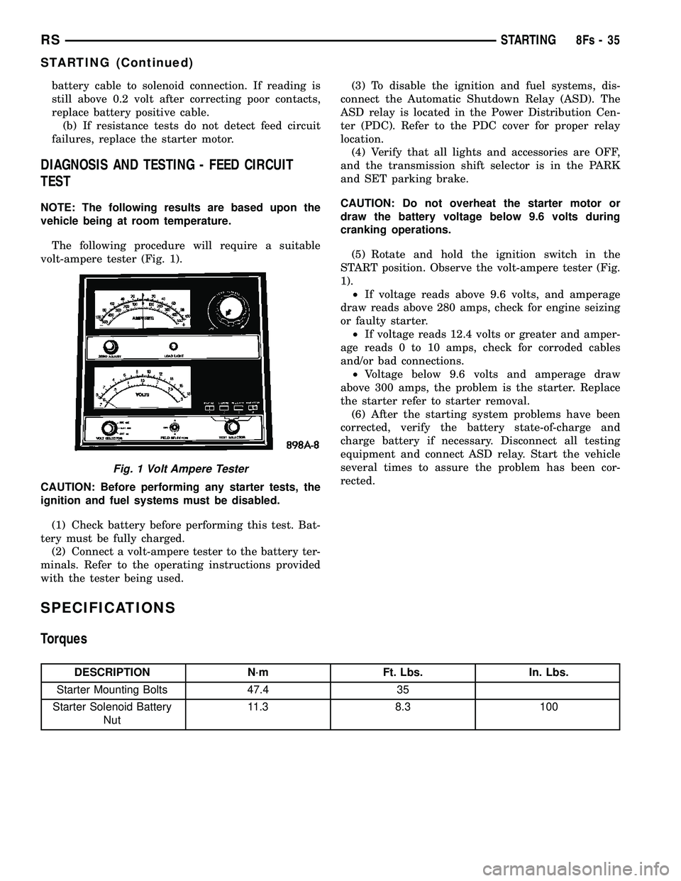
The following procedure will require a suitable
volt-ampere tester (Fig. 1).
CAUTION: Before performing any starter tests, the
ignition and fuel systems must be disabled.
(1) Check battery before performing this test. Bat-
tery must be fully charged. (2) Connect a volt-ampere tester to the battery ter-
minals. Refer to the operating instructions provided
with the tester being used. (3) To disable the ignition and fuel systems, dis-
connect the Automatic Shutdown Relay (ASD). The
ASD relay is located in the Power Distribution Cen-
ter (PDC). Refer to the PDC cover for proper relay
location. (4) Verify that all lights and accessories are OFF,
and the transmission shift selector is in the PARK
and SET parking brake.
CAUTION: Do not overheat the starter motor or
draw the battery voltage below 9.6 volts during
cranking operations.
(5) Rotate and hold the ignition switch in the
START position. Observe the volt-ampere tester (Fig.
1). ² If voltage reads above 9.6 volts, and amperage
draw reads above 280 amps, check for engine seizing
or faulty starter. ² If voltage reads 12.4 volts or greater and amper-
age reads 0 to 10 amps, check for corroded cables
and/or bad connections. ² Voltage below 9.6 volts and amperage draw
above 300 amps, the problem is the starter. Replace
the starter refer to starter removal. (6) After the starting system problems have been
corrected, verify the battery state-of-charge and
charge battery if necessary. Disconnect all testing
equipment and connect ASD relay. Start the vehicle
several times to assure the problem has been cor-
rected.
SPECIFICATIONS
Torques
DESCRIPTION N´m Ft. Lbs. In. Lbs.
Starter Mounting Bolts 47.4 35
Starter Solenoid Battery Nut 11.3 8.3 100
Fig. 1 Volt Ampere Tester
RS
STARTING8Fs-35
STARTING (Continued)
Page 493 of 2585
STARTER
MANUFACTURER NIPPONDENSOEngine Application 2.4L /3.3/3.8L Power rating 1.2 KwVoltage 12 VOLTS
No. of Fields 4 No. of Poles 4 Brushes 4Drive Conventional Gear Train
Free running Test
Voltage 11
Amperage Draw 73 Amp
Minimum Speed 3401 RPM
SolenoidClosing Voltage 7.5 Volts
Cranking Amperage Draw test 150 - 200 Amps.
Engine should be up to operating temperature.
Extremely heavy oil or tight engine will increase
starter amperage draw.
STARTER MOTOR
REMOVAL
REMOVAL - 2.4L
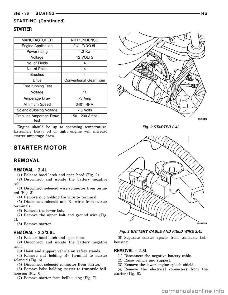
(1) Release hood latch and open hood (Fig. 2).
(2) Disconnect and isolate the battery negative
cable. (3) Disconnect solenoid wire connector from termi-
nal (Fig. 3). (4) Remove nut holding B+ wire to terminal.
(5) Disconnect solenoid and B+ wires from starter
terminals. (6) Remove the lower bolt.
(7) Remove the upper bolt and ground wire (Fig.
4). (8) Remove starter.
REMOVAL - 3.3/3.8L
(1) Release hood latch and open hood.
(2) Disconnect and isolate the battery negative
cable. (3) Hoist and support vehicle on safety stands.
(4) Remove nut holding B+ terminal to starter
solenoid (Fig. 5). (5) Disconnect solenoid connector from starter.
(6) Remove bolts holding starter to transaxle bell-
housing (Fig. 6). (7) Remove starter from bellhousing (Fig. 7). (8) Separate starter spacer from transaxle bell-
housing.
REMOVAL - 2.5L
(1) Disconnect the negative battery cable.
(2) Raise vehicle and support.
(3) Remove the lower engine splash shield.
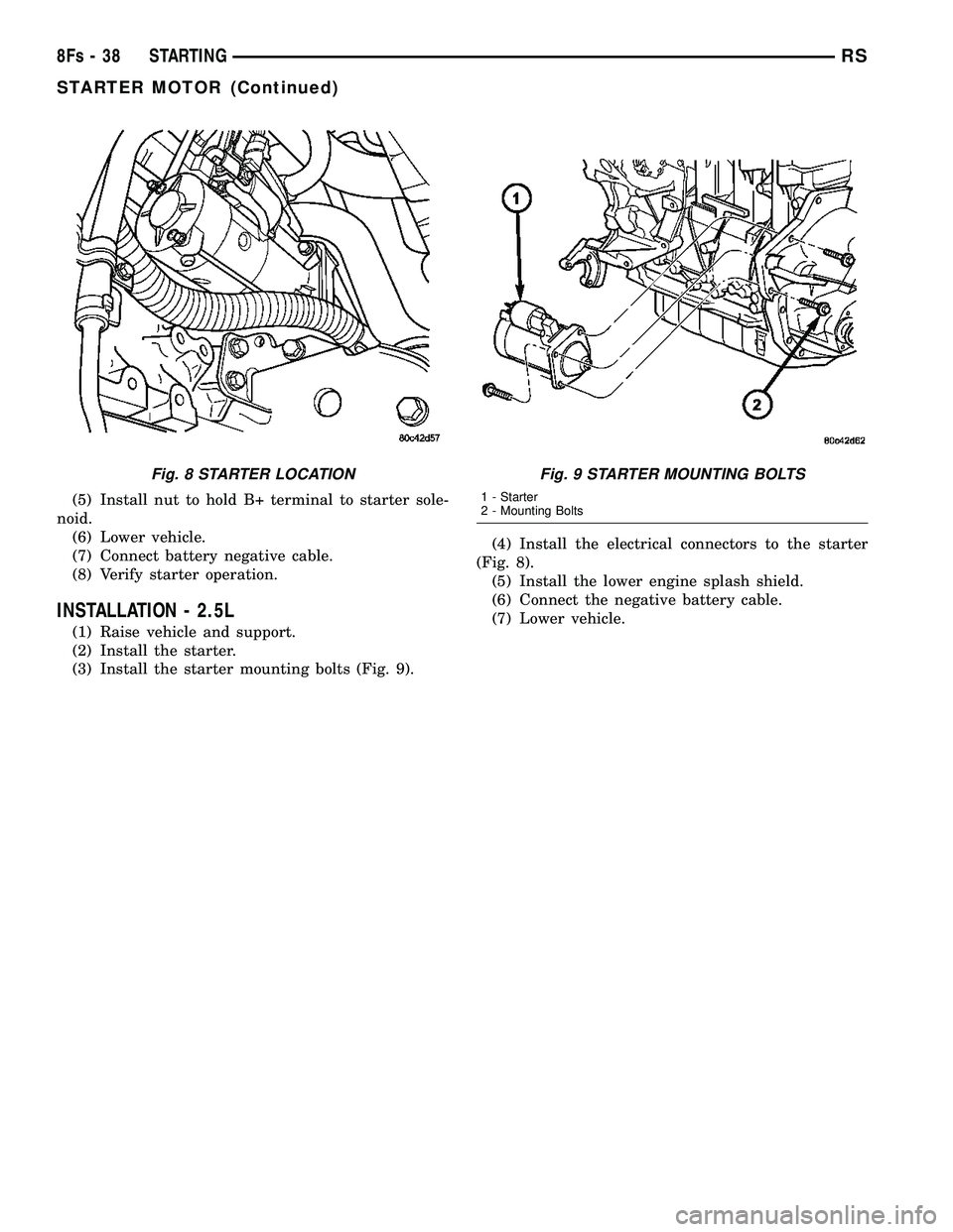
(4) Remove the electrical connectors from the
starter (Fig. 8).
Fig. 2 STARTER 2.4L
Fig. 3 BATTERY CABLE AND FIELD WIRE 2.4L
8Fs - 36 STARTINGRS
STARTING (Continued)
Page 494 of 2585

(5) Remove the starter mounting bolts (Fig. 9).
(6) Remove the starter.
INSTALLATION
INSTALLATION - 2.4L
(1) Place starter in position on vehicle.
(2) Install the lower bolts to hold starter to trans-
axle bellhousing. (3) Install the upper bolt and ground wire (Fig. 4). (4) Place solenoid and B+ wires in position on
starter terminals (Fig. 3). (5) Install nut to hold B+ wire to terminal.
(6) Connect solenoid wire connector onto terminal.
(7) Connect battery negative cable.
(8) Verify starter operation.
INSTALLATION - 3.3/3.8L
(1) Place starter spacer in position on transaxle
bellhousing, flange toward flywheel. (2) Place starter in position on bellhousing.
(3) Install bolts and ground wire (Fig. 4) to hold
starter to transaxle bellhousing. (4) Connect solenoid connector into starter.
Fig. 4 Upper Bolt and Ground Wire
Fig. 5 Starter
1 - SOLENOID CONNECTOR
2 - B+ CONNECTOR
Fig. 6 Starter Bolts
1-STARTER
2 - STARTER BOLTS
3 - TRANSAXLE
4 - ENGINE MOUNT
Fig. 7 STARTER 3.3/3.8L
1 - BELL HOUSING PLATE
2 - FLYWHEEL
3 - ENGINE MOUNT
4-STARTER
5 - SPACER
RS STARTING8Fs-37
STARTER MOTOR (Continued)
Page 495 of 2585
(5) Install nut to hold B+ terminal to starter sole-
noid. (6) Lower vehicle.
(7) Connect battery negative cable.
(8) Verify starter operation.
INSTALLATION - 2.5L
(1) Raise vehicle and support.
(2) Install the starter.
(3) Install the starter mounting bolts (Fig. 9). (4) Install the electrical connectors to the starter
(Fig. 8). (5) Install the lower engine splash shield.
(6) Connect the negative battery cable.
(7) Lower vehicle.
Fig. 8 STARTER LOCATIONFig. 9 STARTER MOUNTING BOLTS
1 - Starter
2 - Mounting Bolts
8Fs - 38 STARTINGRS
STARTER MOTOR (Continued)
Page 498 of 2585
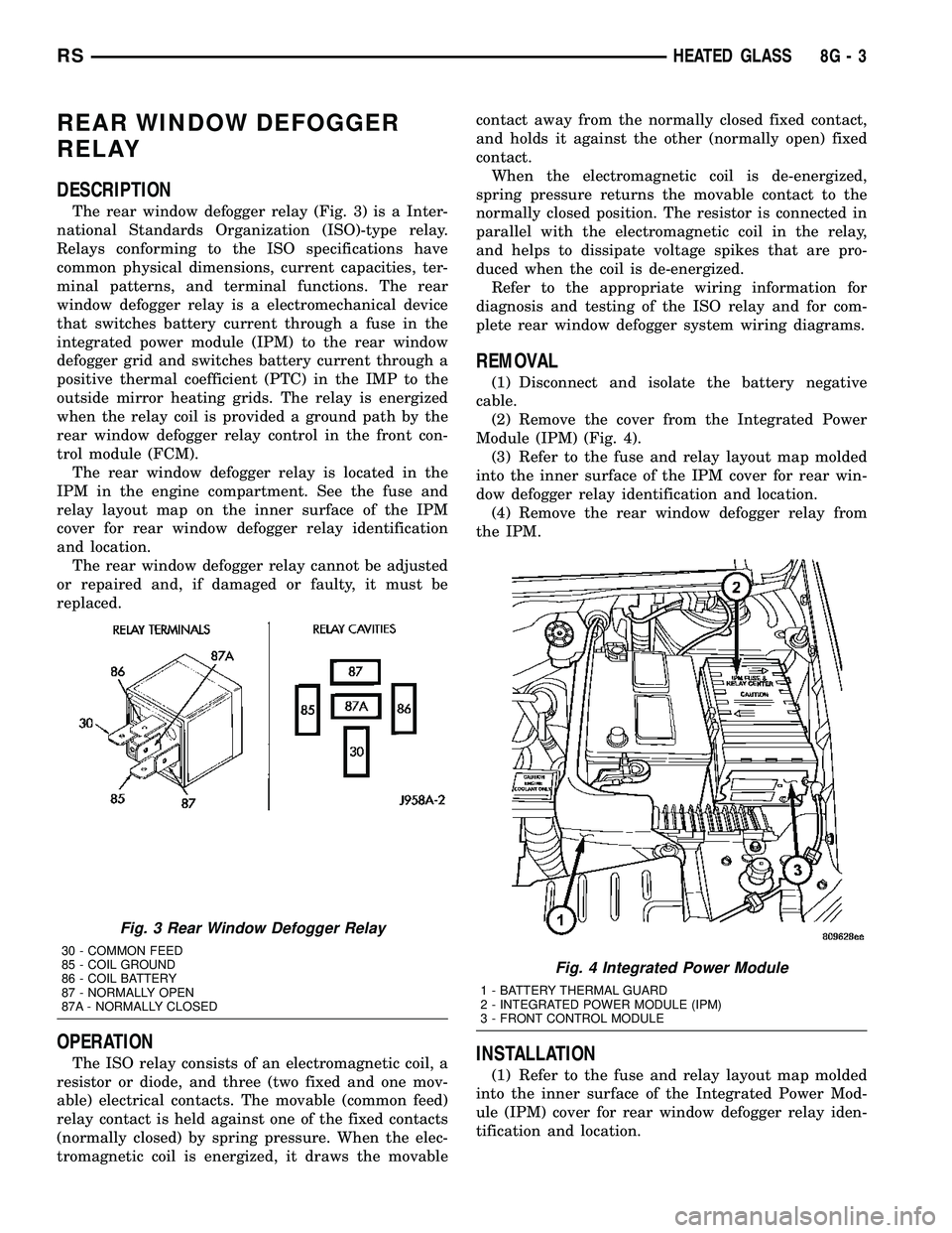
REAR WINDOW DEFOGGER
RELAY
DESCRIPTION
The rear window defogger relay (Fig. 3) is a Inter-
national Standards Organization (ISO)-type relay.
Relays conforming to the ISO specifications have
common physical dimensions, current capacities, ter-
minal patterns, and terminal functions. The rear
window defogger relay is a electromechanical device
that switches battery current through a fuse in the
integrated power module (IPM) to the rear window
defogger grid and switches battery current through a
positive thermal coefficient (PTC) in the IMP to the
outside mirror heating grids. The relay is energized
when the relay coil is provided a ground path by the
rear window defogger relay control in the front con-
trol module (FCM).
The rear window defogger relay is located in the
IPM in the engine compartment. See the fuse and
relay layout map on the inner surface of the IPM
cover for rear window defogger relay identification
and location.
The rear window defogger relay cannot be adjusted
or repaired and, if damaged or faulty, it must be
replaced.
OPERATION
The ISO relay consists of an electromagnetic coil, a
resistor or diode, and three (two fixed and one mov-
able) electrical contacts. The movable (common feed)
relay contact is held against one of the fixed contacts
(normally closed) by spring pressure. When the elec-
tromagnetic coil is energized, it draws the movablecontact away from the normally closed fixed contact,
and holds it against the other (normally open) fixed
contact.
When the electromagnetic coil is de-energized,
spring pressure returns the movable contact to the
normally closed position. The resistor is connected in
parallel with the electromagnetic coil in the relay,
and helps to dissipate voltage spikes that are pro-
duced when the coil is de-energized.
Refer to the appropriate wiring information for
diagnosis and testing of the ISO relay and for com-
plete rear window defogger system wiring diagrams.
REMOVAL
(1) Disconnect and isolate the battery negative
cable.
(2) Remove the cover from the Integrated Power
Module (IPM) (Fig. 4).
(3) Refer to the fuse and relay layout map molded
into the inner surface of the IPM cover for rear win-
dow defogger relay identification and location.
(4) Remove the rear window defogger relay from
the IPM.
INSTALLATION
(1) Refer to the fuse and relay layout map molded
into the inner surface of the Integrated Power Mod-
ule (IPM) cover for rear window defogger relay iden-
tification and location.
Fig. 3 Rear Window Defogger Relay
30 - COMMON FEED
85 - COIL GROUND
86 - COIL BATTERY
87 - NORMALLY OPEN
87A - NORMALLY CLOSED
Fig. 4 Integrated Power Module
1 - BATTERY THERMAL GUARD
2 - INTEGRATED POWER MODULE (IPM)
3 - FRONT CONTROL MODULE
RSHEATED GLASS8G-3
Page 510 of 2585

HORN
TABLE OF CONTENTS
page page
HORN SYSTEM
DESCRIPTION..........................1
OPERATION............................1
DIAGNOSIS AND TESTING - HORN SYSTEM . . . 1
HORN
DIAGNOSIS AND TESTING - HORN..........3REMOVAL.............................4
INSTALLATION..........................5
HORN SWITCH
DESCRIPTION..........................5
HORN SYSTEM
DESCRIPTION
WARNING: ON VEHICLES EQUIPPED WITH AIR-
BAG, REFER TO ELECTRICAL, RESTRAINTS FOR
SAFETY PRECAUTIONS. DISCONNECT THE NEGA-
TIVE CABLE FROM THE BATTERY BEFORE SER-
VICING COMPONENTS INVOLVING THE AIRBAG
SYSTEM. ACCIDENTAL DEPLOYMENT OF AIRBAG
AND PERSONAL INJURY CAN RESULT.
The horn circuit consists of a horn switch, clock-
spring, horn relay, horns and Integrated Power Mod-
ule (IPM). The horn switch is a membrane switch
located in the airbag trim cover. The horns are
located forward of the left front wheel behind the
bumper fascia.
OPERATION
The horn relay plugs into the Integrated Power
Module (IPM) which is located in the engine com-
partment. For circuit information and component
locations, refer to the appropriate wiring information.
The wiring information includes wiring diagrams,
proper wire and connector repair procedures, details
of wire harness routing and retention, connector pin-
out information and location views for the various
wire harness connectors, splices and grounds.
The horns will not function if the switch is
ªCLOSEDº for more than 30 seconds. Once the
switch is ªOPENº, a 20±30 second delay will occur
before the horns are functional again.
DIAGNOSIS AND TESTING - HORN SYSTEM
WARNING: ON VEHICLES EQUIPPED WITH AIR-
BAGS, REFER TO ELECTRICAL, RESTRAINTS
BEFORE ATTEMPTING ANY STEERING WHEEL,
STEERING COLUMN, OR INSTRUMENT PANEL
COMPONENT DIAGNOSIS OR SERVICE. FAILURE
TO TAKE THE PROPER PRECAUTIONS COULD
RESULT IN ACCIDENTAL AIRBAG DEPLOYMENT
AND POSSIBLE PERSONAL INJURY.
Refer to Horn System Test below. If the horn does
not sound, check horn fuse located in the Integrated
Power Module (IPM). If the fuse is blown, replace
with the correct fuse. If the horns fail to sound and
the new fuse blows when depressing the horn switch,
a short circuit in the horn or the horn wiring
between the fuse terminal and the horn is responsi-
ble, or a defective horn switch allowed the horn to
burn out is responsible.
If the fuse is OK, test horn relay (Refer to 8 -
ELECTRICAL/HORN/HORN RELAY - DIAGNOSIS
AND TESTING).
If the relay is OK, test horn. Refer to Horn System
Test.
CAUTION: Continuous sounding of horn may
cause horn failure.
Should the horn sound continuously:
²Unplug the horn relay from IPM.
²Refer to (Refer to 8 - ELECTRICAL/HORN/
HORN RELAY - DIAGNOSIS AND TESTING).
Refer to the appropriate wiring information.
RSHORN8H-1
Page 516 of 2585

IGNITION CONTROL
TABLE OF CONTENTS
page page
IGNITION CONTROL
DESCRIPTION - IGNITION SYSTEM..........1
OPERATION - IGNITION SYSTEM...........1
SPECIFICATIONS
TORQUE.............................2
SPARK PLUG CABLE RESISTANCE........2
SPARK PLUG.........................2
FIRING ORDER........................3
AUTO SHUT DOWN RELAY
DESCRIPTION..........................3
OPERATION............................3
CAMSHAFT POSITION SENSOR
DESCRIPTION..........................4
OPERATION............................4
REMOVAL
REMOVAL - 2.4L.......................5
REMOVAL - 3.3/3.8L....................5
INSTALLATION
INSTALLATION - 2.4L...................6
INSTALLATION - 3.3/3.8L.................6
IGNITION COIL
DESCRIPTION..........................6
OPERATION............................7
REMOVAL
REMOVAL - 2.4L.......................7REMOVAL - 3.3/3.8L....................7
INSTALLATION
INSTALLATION - 2.4L...................7
INSTALLATION - 3.3/3.8L.................7
KNOCK SENSOR
DESCRIPTION..........................8
OPERATION............................8
REMOVAL
REMOVAL - 2.4L.......................8
REMOVAL - 3.8L.......................8
INSTALLATION
INSTALLATION - 2.4L...................9
INSTALLATION - 3.8L...................9
SPARK PLUG
DESCRIPTION
DESCRIPTION - STANDARD 4 CYLINDER . . . 9
DESCRIPTION - PLATINUM PLUGS........9
REMOVAL.............................10
INSTALLATION.........................10
SPARK PLUG CABLE
DESCRIPTION.........................10
REMOVAL - 2.0/2.4L.....................10
INSTALLATION - 2.0/2.4L.................10
IGNITION CONTROL
DESCRIPTION - IGNITION SYSTEM
NOTE: All engines use a fixed ignition timing sys-
tem. Basic ignition timing is not adjustable. All
spark advance is determined by the Powertrain
Control Module (PCM).
The ignition system used on these engines is
referred to as the Direct Ignition System (DIS). The
system's three main components are the coils, crank-
shaft position sensor, and camshaft position sensor. If
equipped with the coil on plug ignition system it uti-
lizes an ignition coil for every cylinder, it is mounted
directly over the each spark plug.
OPERATION - IGNITION SYSTEM
The crankshaft position sensor and camshaft posi-
tion sensor are hall effect devices. The camshaft posi-
tion sensor and crankshaft position sensor generate
pulses that are inputs to the PCM. The PCM deter-
mines engine position from these sensors. The PCM
calculates injector sequence and ignition timing from
crankshaft & camshaft position. For a description of
both sensors, refer to Camshaft Position Sensor and
Crankshaft Position Sensor.
RSIGNITION CONTROL8I-1