buttons CHRYSLER VOYAGER 2004 User Guide
[x] Cancel search | Manufacturer: CHRYSLER, Model Year: 2004, Model line: VOYAGER, Model: CHRYSLER VOYAGER 2004Pages: 2585, PDF Size: 62.54 MB
Page 614 of 2585
STANDARD PROCEDURE - RKE TRANSMITTER
PROGRAMING
(1) Using a functional key fob transmitter, unlock
the vehicle and disarm the Vehicle Theft Security
System.
(2) Insert ignition key into the ignition switch.
(3) Turn the ignition switch to RUN position with-
out starting engine.
(4) Using a functional key fob transmitter, press
and hold the UNLOCK button for a minimum five
seconds (maximum ten seconds).
(5) While still holding UNLOCK button, and
before ten seconds passes, press the PANIC button
and release both at the same time. A single chime
will sound to indicate that the transmitter program-
ming mode has been entered (allow 3 seconds for
chime to sound).
(6) Within 30 seconds of the chime, press and
release the ªLOCKº and ªUNLOCKº buttons on the
transmitter at the same time. Then press and release
any button on the same transmitter and a chime will
sound after successfully programming the transmit-
ter.
(7) Repeat steps 5 and 6 for all transmitters that
will be used with this vehicle (up to 4 total).
(8) Turn ignition to the OFF position. Transmitter
programming mode will discontinue after 60 seconds.
All transmitter programming must be com-
pleted within time specified.
SPECIFICATIONS
RANGE
Normal operation range is up to a distance of 7
meters (23 ft.) of the vehicle. Range may be better or
worse depending on the environment around the
vehicle. Closeness to a radio frequency transmitter
such as a radio station tower that is broadcasting on
105 MHz FM or a 156 MHz 2±way communication
station, may degrade operational range, while range
in an open field will be enhanced.
BATTERY
The batteries can be removed without special tools
and are readily available at local retail stores. Therecommended battery is Duracell DL 2016 or equiva-
lent, TWO cells are required. Battery life is about
three years minimum.
CAUTION: Do not touch the battery terminals or
handle the batteries any more than necessary.
Hands must be clean and dry.
REMOTE KEYLESS ENTRY
MODULE
DESCRIPTION
The RKE module is capable of retaining up to four
different Vehicle Access Codes.
OPERATION
Whenever the vehicle battery power is interrupted
the RKE Module will retain all vehicle access codes
in its memory. When replacing or adding a key fob
transmitter (maximum 4) a DRB IIItscan tool is
required to program the RKE Module to accept the
new Vehicle Access Code if a customer owned trans-
mitter is not available. Refer to Electrical, Remote
Keyless Entry Module, Standard Procedure - Pro-
gramming RKE Module or the Proper Body Diagnos-
tic Procedures manual.
DIAGNOSIS AND TESTING - REMOTE KEYLESS
ENTRY MODULE
Refer to the appropriate wiring information. The
wiring information includes wiring diagrams, proper
wire and connector repair procedures, further details
on wire harness routing and retention, as well as
pin-out and location views for the various wire har-
ness connectors, splices and grounds. Refer to the
proper Body Diagnostic Procedures Manual for test-
ing the Remote Keyless Entry system using a
DRB IIItscan tool. Also refer to other interrelated
systems groups within this manual:
²Vehicle Theft Security System
²Power Seats
²Power Mirrors
RSPOWER LOCKS8N-43
KEYLESS ENTRY TRANSMITTER (Continued)
Page 627 of 2585
OPERATION
The memory switch has three momentary switch
buttons labeled Set, 1 and 2. When the memory set
switch is depressed, a resistance value is sent to the
Body Control Module via hard wired connections.
When the memory system is in ªsetº mode a chime
will be generated by the body control module.
See the owner's manual in the vehicle glove box for
more information on the features, use and operation
of the memory switch.
DIAGNOSIS AND TESTING - MEMORY SWITCH
(1) Remove the memory set switch from the driv-
ers door panel (Refer to 8 - ELECTRICAL/POWER
SEATS/MEMORY SET SWITCH - REMOVAL).
(2) Using an ohmmeter, check the continuity of the
memory select switch MUX circuit between the C2
wire harness connector for the body control module
and the wire harness connector for the memory
switch. There should be continuity. If OK, go to Step
3. If not OK, repair the open or shorted MUX circuit
as required.
(3) Using an ohmmeter, check the continuity of the
memory select switch return circuit between the C2
wire harness connector for the body control module
and the wire harness connector for the memory
switch. There should be continuity. If OK, go to Step
4. If not OK, repair the open or shorted return circuit
as required.
(4) Using an ohmmeter, test the resistances of the
memory switch at the pins in the switch connector
receptacle in each switch position. See the Memory
Switch Test Table. If OK, refer toDiagnosis and
Testing Memory Systemin this section. If not OK,
replace the faulty memory set switch.
MEMORY SWITCH TEST TABLE
MEMORY
SWITCH
POSITIONRESISTANCE
BETWEEN
PINSRESISTANCE
RANGE
(OHMS)
NEUTRAL 1&2 24650 5%
(24.65 k)
MEMORY 1 1&2 6850 5%
(6.85 k)
MEMORY 2 1&2 2100 5%
(2.10 k)
SET 1&2 4490 5%
(4.49 k)
REMOVAL
(1) Disconnect and isolate the battery negative
cable.
(2) Remove the front door trim panel switch bezel
from the driver side front door. Using a thin flat-bladed pry tool, gently pry the switch bezel away
from the drivers door trim panel.
(3) Disconnect the memory switch wire harness
connector from the memory switch.
(4) Remove the two screws that secure the memory
switch to the back of the driver side front door trim
panel switch bezel.
(5) Remove the memory switch.
INSTALLATION
(1) Position the memory switch and install and
tighten the two screws that secure the memory
switch to the back of the driver side front door trim
panel switch bezel. Tighten the screws to 2.2 N´m (20
in. lbs.).
(2) Reconnect the memory switch wire harness
connector to the memory switch.
(3) Install the trim panel switch bezel onto the
driver side front door.
(4) Reconnect the battery negative cable.
PASSENGER SEAT SWITCH
DESCRIPTION
Vehicles equipped with a passenger side power seat
utilize a four-way power seat switch. This four-way
power seat switch features two knobs ganged
together on the outboard seat cushion side shield.
The switch is secured to the back of the seat cush-
ion side shield with two screws. However, the control
knobs for the seat switch unit must be removed
before the seat switch can be removed from the side
shield.
The power seat switch cannot be repaired. If one
switch is damaged or faulty, the entire power seat
switch unit must be replaced.
OPERATION
When a power seat switch control knob or knobs
are actuated, a battery feed and a ground path are
applied through the switch contacts to the power seat
track or recliner adjuster motor. The selected
adjuster motor operates to move the seat track or
recliner through its drive unit in the selected direc-
tion until the switch is released, or until the travel
limit of the adjuster is reached. When the switch is
moved in the opposite direction, the battery feed and
ground path to the motor are reversed through the
switch contacts. This causes the adjuster motor to
run in the opposite direction.
No power seat switch should be held applied in any
direction after the adjuster has reached its travel
limit. The power seat adjuster motors each contain a
self-resetting circuit breaker to protect them from
overload. However, consecutive or frequent resetting
8N - 56 POWER SEAT SYSTEMRS
MEMORY SET SWITCH (Continued)
Page 642 of 2585
KEYLESS ENTRY
TRANSMITTER
DIAGNOSIS AND TESTING - KEYLESS ENTRY
TRANSMITTER
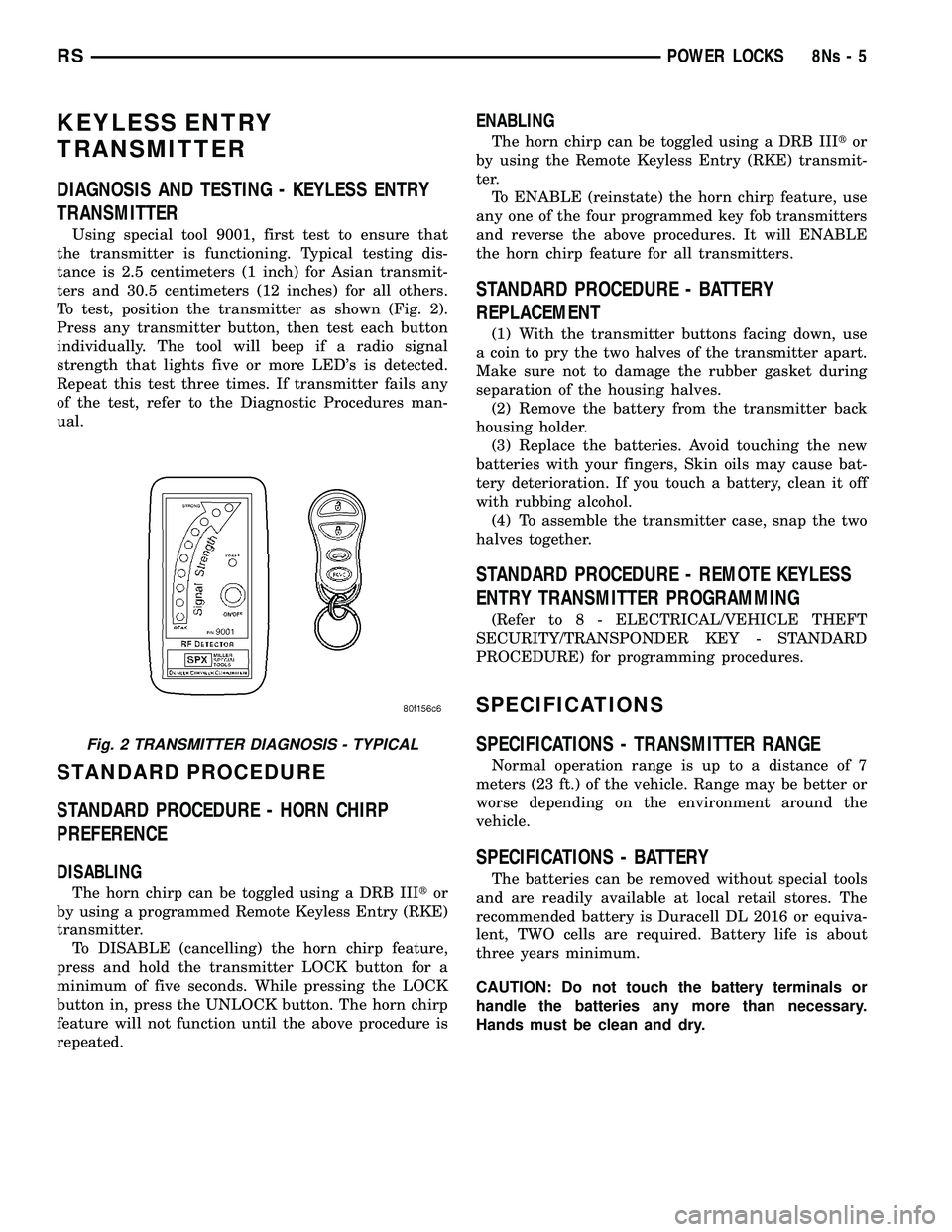
Using special tool 9001, first test to ensure that
the transmitter is functioning. Typical testing dis-
tance is 2.5 centimeters (1 inch) for Asian transmit-
ters and 30.5 centimeters (12 inches) for all others.
To test, position the transmitter as shown (Fig. 2).
Press any transmitter button, then test each button
individually. The tool will beep if a radio signal
strength that lights five or more LED's is detected.
Repeat this test three times. If transmitter fails any
of the test, refer to the Diagnostic Procedures man-
ual.
STANDARD PROCEDURE
STANDARD PROCEDURE - HORN CHIRP
PREFERENCE
DISABLING
The horn chirp can be toggled using a DRB III tor
by using a programmed Remote Keyless Entry (RKE)
transmitter. To DISABLE (cancelling) the horn chirp feature,
press and hold the transmitter LOCK button for a
minimum of five seconds. While pressing the LOCK
button in, press the UNLOCK button. The horn chirp
feature will not function until the above procedure is
repeated.
ENABLING
The horn chirp can be toggled using a DRB III tor
by using the Remote Keyless Entry (RKE) transmit-
ter. To ENABLE (reinstate) the horn chirp feature, use
any one of the four programmed key fob transmitters
and reverse the above procedures. It will ENABLE
the horn chirp feature for all transmitters.
STANDARD PROCEDURE - BATTERY
REPLACEMENT
(1) With the transmitter buttons facing down, use
a coin to pry the two halves of the transmitter apart.
Make sure not to damage the rubber gasket during
separation of the housing halves. (2) Remove the battery from the transmitter back
housing holder. (3) Replace the batteries. Avoid touching the new
batteries with your fingers, Skin oils may cause bat-
tery deterioration. If you touch a battery, clean it off
with rubbing alcohol. (4) To assemble the transmitter case, snap the two
halves together.
STANDARD PROCEDURE - REMOTE KEYLESS
ENTRY TRANSMITTER PROGRAMMING
(Refer t o 8 - ELECTRICAL/VEHICLE THEFT
SECURITY/TRANSPONDER KEY - STANDARD
PROCEDURE) for programming procedures.
SPECIFICATIONS
SPECIFICATIONS - TRANSMITTER RANGE
Normal operation range is up to a distance of 7
meters (23 ft.) of the vehicle. Range may be better or
worse depending on the environment around the
vehicle.
SPECIFICATIONS - BATTERY
The batteries can be removed without special tools
and are readily available at local retail stores. The
recommended battery is Duracell DL 2016 or equiva-
lent, TWO cells are required. Battery life is about
three years minimum.
CAUTION: Do not touch the battery terminals or
handle the batteries any more than necessary.
Hands must be clean and dry.
Fig. 2 TRANSMITTER DIAGNOSIS - TYPICAL
RS POWER LOCKS8Ns-5
Page 650 of 2585
OPERATION
The memory switch has three momentary switch
buttons labeled Set, 1 and 2. When the memory set
switch is depressed, a resistance value is sent to the
Body Control Module via hard wired connections.
When the memory system is in ªsetº mode a chime
will be generated by the body control module. See the owner's manual in the vehicle glove box for
more information on the features, use and operation
of the memory switch.
DIAGNOSIS AND TESTING - MEMORY SWITCH
(1) Remove the memory set switch from the driv-
ers door panel (Refer t o 8 - ELECTRICAL/POWER
SEATS/MEMORY SET SWITCH - REMOVAL). (2) Using an ohmmeter, check the continuity of the
memory select switch MUX circuit between the C2
wire harness connector for the body control module
and the wire harness connector for the memory
switch. There should be continuity. If OK, go to Step
3. If not OK, repair the open or shorted MUX circuit
as required. (3) Using an ohmmeter, check the continuity of the
memory select switch return circuit between the C2
wire harness connector for the body control module
and the wire harness connector for the memory
switch. There should be continuity. If OK, go to Step
4. If not OK, repair the open or shorted return circuit
as required. (4) Using an ohmmeter, test the resistances of the
memory switch at the pins in the switch connector
receptacle in each switch position. See the Memory
Switch Test Table. If OK, refer to Diagnosis and
Testing Memory System in this section. If not OK,
replace the faulty memory set switch.
MEMORY SWITCH TEST TABLE
MEMORY SWITCH
POSITION RESISTANCE
BETWEEN PINS RESISTANCE
RANGE
(OHMS)
NEUTRAL 1&2 24650 5% (24.65 k)
MEMORY 1 1&2 6850 5% (6.85 k)
MEMORY 2 1&2 2100 5% (2.10 k)
SET 1&2 4490 5% (4.49 k)
REMOVAL
(1) Disconnect and isolate the battery negative
cable. (2) Remove the front door trim panel switch bezel
from the driver side front door. Using a thin flat-
bladed pry tool, gently pry the switch bezel away
from the drivers door trim panel. (3) Disconnect the memory switch wire harness
connector from the memory switch. (4) Remove the two screws that secure the memory
switch to the back of the driver side front door trim
panel switch bezel. (5) Remove the memory switch.
INSTALLATION
(1) Position the memory switch and install and
tighten the two screws that secure the memory
switch to the back of the driver side front door trim
panel switch bezel. Tighten the screws to 2.2 N´m (20
in. lbs.). (2) Reconnect the memory switch wire harness
connector to the memory switch. (3) Install the trim panel switch bezel onto the
driver side front door. (4) Reconnect the battery negative cable.
PASSENGER SEAT SWITCH
DESCRIPTION
Vehicles equipped with a passenger side power seat
utilize a four-way power seat switch. This four-way
power seat switch features two knobs ganged
together on the outboard seat cushion side shield. The switch is secured to the back of the seat cush-
ion side shield with two screws. However, the control
knobs for the seat switch unit must be removed
before the seat switch can be removed from the side
shield. The power seat switch cannot be repaired. If one
switch is damaged or faulty, the entire power seat
switch unit must be replaced.
OPERATION
When a power seat switch control knob or knobs
are actuated, a battery feed and a ground path are
applied through the switch contacts to the power seat
track or recliner adjuster motor. The selected
adjuster motor operates to move the seat track or
recliner through its drive unit in the selected direc-
tion until the switch is released, or until the travel
limit of the adjuster is reached. When the switch is
moved in the opposite direction, the battery feed and
ground path to the motor are reversed through the
switch contacts. This causes the adjuster motor to
run in the opposite direction.
RS POWER SEAT SYSTEM8Ns-13
MEMORY SET SWITCH (Continued)
Page 674 of 2585
SPEED CONTROL
TABLE OF CONTENTS
page page
SPEED CONTROL
DESCRIPTION..........................1
OPERATION
OPERATION..........................1
OPERATION - INTERACTIVE SPEED
CONTROL (4 Speed EATX Only)...........2
DIAGNOSIS AND TESTING - ROAD TEST.....3
SPECIFICATIONS - TORQUE...............3
CABLE
DESCRIPTION..........................4
OPERATION............................4
REMOVAL.............................4
INSTALLATION..........................4
SERVO
DESCRIPTION..........................4OPERATION............................4
REMOVAL.............................5
INSTALLATION..........................5
SWITCH
DESCRIPTION..........................6
OPERATION............................6
REMOVAL.............................6
INSTALLATION..........................6
VACUUM RESERVOIR
DESCRIPTION..........................6
OPERATION............................6
REMOVAL.............................6
INSTALLATION..........................6
SPEED CONTROL
DESCRIPTION
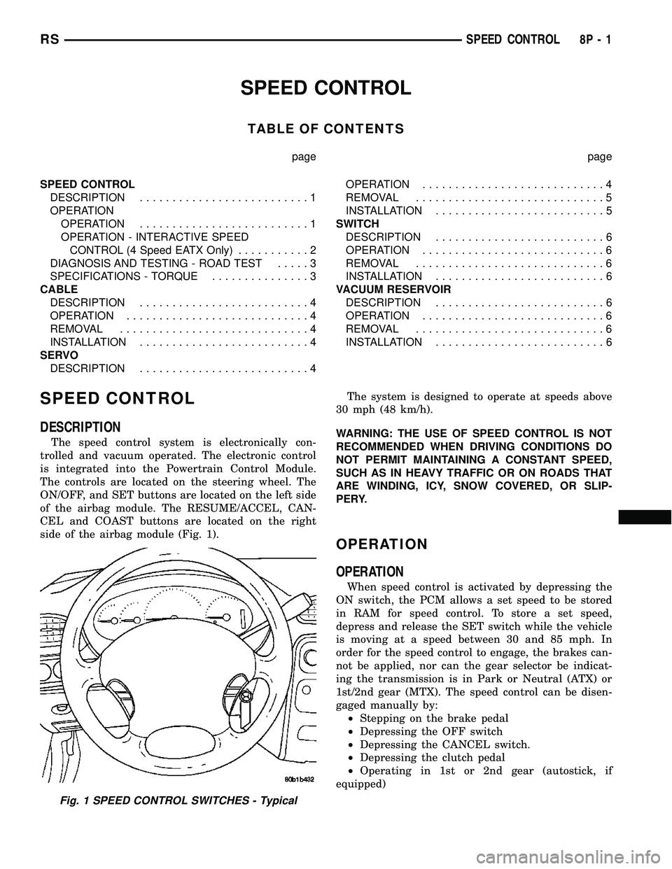
The speed control system is electronically con-
trolled and vacuum operated. The electronic control
is integrated into the Powertrain Control Module.
The controls are located on the steering wheel. The
ON/OFF, and SET buttons are located on the left side
of the airbag module. The RESUME/ACCEL, CAN-
CEL and COAST buttons are located on the right
side of the airbag module (Fig. 1).The system is designed to operate at speeds above
30 mph (48 km/h).
WARNING: THE USE OF SPEED CONTROL IS NOT
RECOMMENDED WHEN DRIVING CONDITIONS DO
NOT PERMIT MAINTAINING A CONSTANT SPEED,
SUCH AS IN HEAVY TRAFFIC OR ON ROADS THAT
ARE WINDING, ICY, SNOW COVERED, OR SLIP-
PERY.
OPERATION
OPERATION
When speed control is activated by depressing the
ON switch, the PCM allows a set speed to be stored
in RAM for speed control. To store a set speed,
depress and release the SET switch while the vehicle
is moving at a speed between 30 and 85 mph. In
order for the speed control to engage, the brakes can-
not be applied, nor can the gear selector be indicat-
ing the transmission is in Park or Neutral (ATX) or
1st/2nd gear (MTX). The speed control can be disen-
gaged manually by:
²Stepping on the brake pedal
²Depressing the OFF switch
²Depressing the CANCEL switch.
²Depressing the clutch pedal
²Operating in 1st or 2nd gear (autostick, if
equipped)
Fig. 1 SPEED CONTROL SWITCHES - Typical
RSSPEED CONTROL8P-1
Page 679 of 2585
SWITCH
DESCRIPTION
There are two separate switch pods that operate
the speed control system and are located on the
steering wheel.
OPERATION
The speed control system has five separate resis-
tive switches that provide a single multiplexed
(MUX) voltage inputs to the PCM.The switch names
are: ON, OFF, SET, COAST, RESUME, ACCEL, TAP-
UP, COAST, and CANCEL. Based on conditions when
the buttons are pushed (and released), the five volt-
ages ranges provided to the PCM result in the follow-
ing functions: ON, OFF, SET, COAST, RESUME,
ACCEL, TAP-UP, TAP-DOWN, COAST, and CAN-
CEL. Refer to the Speed Control Section for more
information
Also the PCM receives an input from the brake
switch to sense whether the brake pedal has been
depressed. When the PCM receives the brake
depressed input, it turns off power to the speed con-
trol servo and disengages speed control. Also the
power to the servo is supplied through the brake
switch, which opens the circuit when the brake pedal
is depressed.
The individual switches cannot be repaired. If one
switch fails, the entire switch module must be
replaced.
REMOVAL
The speed control switches are mounted in the
steering wheel and wired through the clock spring
device under the airbag module.
WARNING: IF REMOVAL OF AIRBAG MODULE IS
NECESSARY, REFER TO THE RESTRAINT SYS-
TEMS SECTION FOR MORE INFORMATION.
(1) Remove the negative battery cable.
(2) Turn off ignition.
(3) Remove the air bag, refer to the restraint sec-
tion for more information.
(4) Remove the screw from bottom of the switch.
(5) Remove switch from steering wheel.
(6) Disconnect two-way electrical connector.
(7) Repeat for the other switch.
INSTALLATION
The speed control switches are mounted in the
steering wheel and wired through the clock spring
device under the airbag module.WARNING: IF REMOVAL OF AIRBAG MODULE IS
NECESSARY, REFER TO THE RESTRAINT SYS-
TEMS SECTION FOR MORE INFORMATION.
(1) Connect two-way electrical connector.
(2) Install switch.
(3) Install screw for the switch.
(4) Repeat for the other switch.
(5) Install the air bag, refer to the restraint section
for more information.
(6) Install the negative battery cable.
VACUUM RESERVOIR
DESCRIPTION
The vacuum reservoir is located in the engine com-
partment. It is made of plastic.
OPERATION
The reservoir stores engine vacuum. Manifold vac-
uum is supplied from the brake booster check valve.
The speed control vacuum supply hose has a check
valve at the source (brake booster) to maintain the
highest available vacuum level in the servo, reservoir
and vacuum hoses. When engine vacuum drops, as in
climbing a grade while driving, the reservoir supplies
the vacuum needed to maintain proper speed control
operation. The vacuum reservoir cannot be repaired
and must be replaced if faulty.
REMOVAL
(1) Release hood latch and open hood.
(2) Disconnect the negative battery cable.
(3) Disconnect the vacuum line to the battery tray/
vacuum reservoir.
(4) Remove battery tray/vacuum reservoir, refer to
the Battery section for more information.
INSTALLATION
(1) Install battery tray/vacuum reservoir, refer to
the Battery section for more information.
(2) Connect vacuum line that leads to the battery
tray/vacuum reservoir.
(3) Connect the negative battery cable.
8P - 6 SPEED CONTROLRS
Page 1657 of 2585
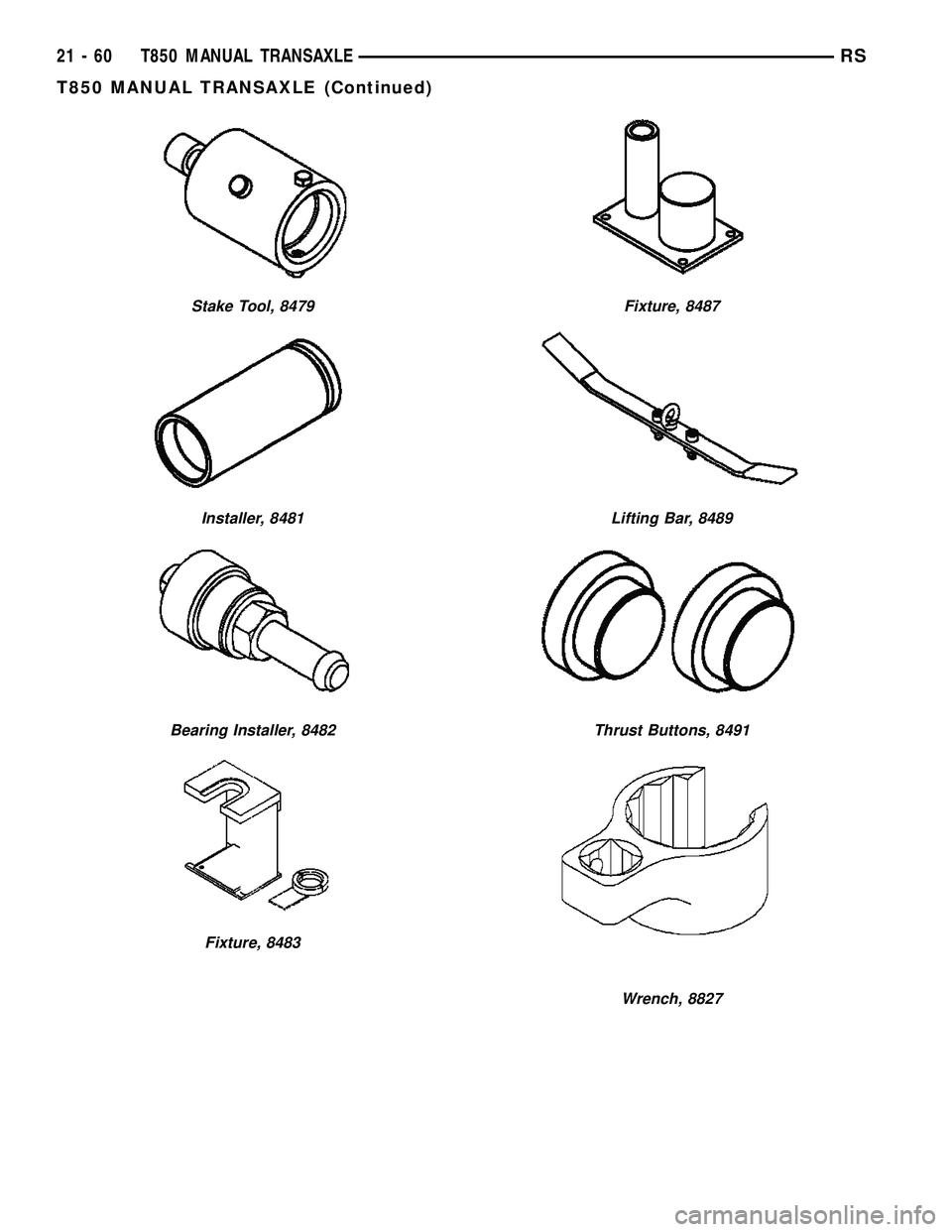
Stake Tool, 8479
Installer, 8481
Bearing Installer, 8482
Fixture, 8483
Fixture, 8487
Lifting Bar, 8489
Thrust Buttons, 8491
Wrench, 8827
21 - 60 T850 MANUAL TRANSAXLERS
T850 MANUAL TRANSAXLE (Continued)
Page 1665 of 2585
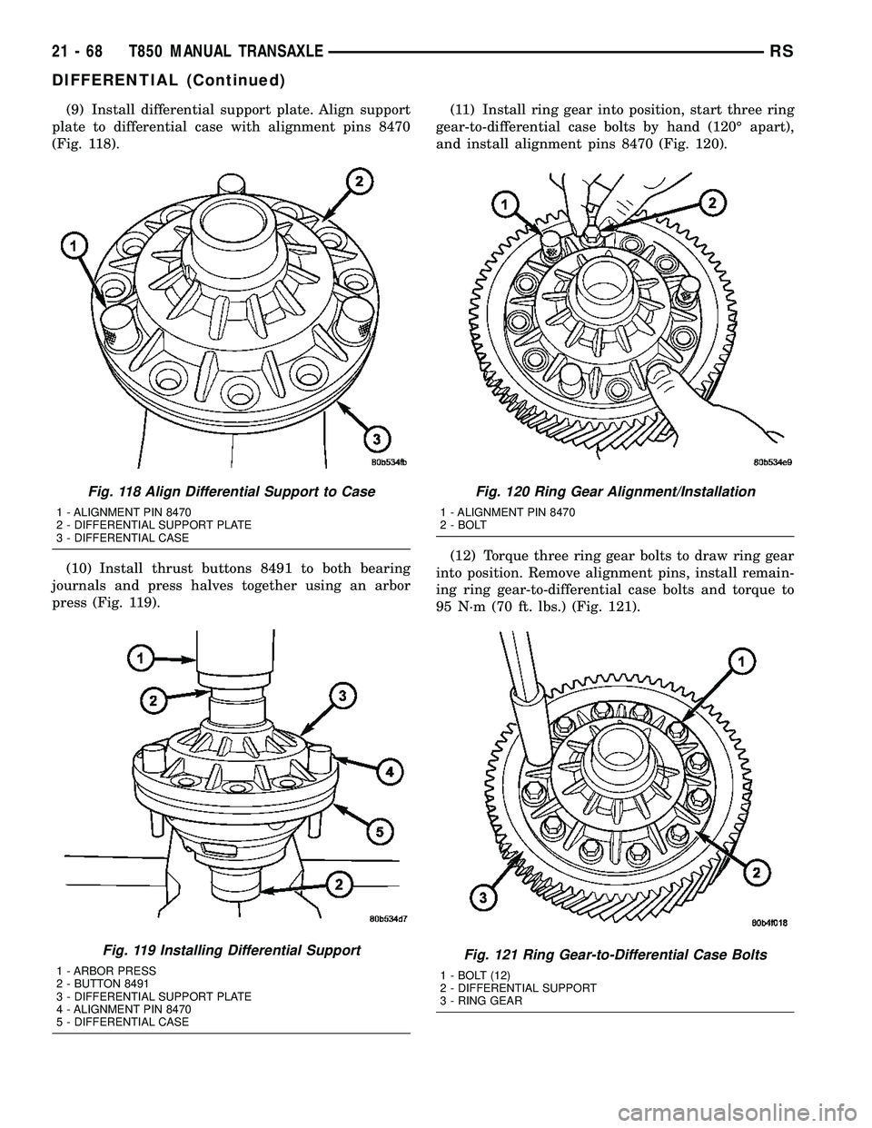
(9) Install differential support plate. Align support
plate to differential case with alignment pins 8470
(Fig. 118).
(10) Install thrust buttons 8491 to both bearing
journals and press halves together using an arbor
press (Fig. 119).(11) Install ring gear into position, start three ring
gear-to-differential case bolts by hand (120É apart),
and install alignment pins 8470 (Fig. 120).
(12) Torque three ring gear bolts to draw ring gear
into position. Remove alignment pins, install remain-
ing ring gear-to-differential case bolts and torque to
95 N´m (70 ft. lbs.) (Fig. 121).
Fig. 118 Align Differential Support to Case
1 - ALIGNMENT PIN 8470
2 - DIFFERENTIAL SUPPORT PLATE
3 - DIFFERENTIAL CASE
Fig. 119 Installing Differential Support
1 - ARBOR PRESS
2 - BUTTON 8491
3 - DIFFERENTIAL SUPPORT PLATE
4 - ALIGNMENT PIN 8470
5 - DIFFERENTIAL CASE
Fig. 120 Ring Gear Alignment/Installation
1 - ALIGNMENT PIN 8470
2 - BOLT
Fig. 121 Ring Gear-to-Differential Case Bolts
1 - BOLT (12)
2 - DIFFERENTIAL SUPPORT
3 - RING GEAR
21 - 68 T850 MANUAL TRANSAXLERS
DIFFERENTIAL (Continued)
Page 2401 of 2585
²FAN/MODE± The Fan and Mode knobs have
17 manual selectable positions. Manually changing
either of the rotary knobs for mode or fan speed set-
tings makes control of that blowe motor manual. If
only one is changed manually, the other remains
under automatic control. Pressing the HI-AUTO/LO-
AUTO rocker switch restores full automatic control.
²REAR CONTROL± When the Rear System
control knob is moved to the OFF position, there will
be a delay of approximately 1 second before the sys-
tem actually turns off. This delay is to prevent an
undesired blower dropout if the knob is moved
through OFF to the other selections.
²BLOWER DELAY TIMER± The word DELAY
is displayed at start-up to signify that the system is
waiting so that cold air will not be blowing. This tells
the operator that it is unnecessary to turn the sys-
tem off, raise the temperature setting or turn the fan
speed setting down to prevent cold air from blowing.
A countdown in minutes and seconds until the engine
is warm enough to begin delivering heat to the pas-
sengers alternates with the DELAY message at 25
second intervals. This countdown is based on actual
measurement of the rate of engine coolant tempera-
ture change. During the delay time, mix mode is
selected and the fan operates at a low speed to keep
the windshield fog free.
REAR CONTROL PANEL
Primary control of the rear compartment unit is in
the instrument panel center stack. The rear unit con-
trol knob there allows the driver to turn the rear
unit off, allow control by the intermediate seat occu-
pants by switching to the REAR position, or provide
fully automatic control based on the temperature set-
ting shown on the front control display.
²REAR CONTROL± Selecting automatic control
of the rear unit at the instrument panel, illuminates
a Locked Padlock in the rear control panel display.
Selecting REAR activates the rear control panel and
the Padlock then appears unlocked.
²FAN KNOB± The rear fan control has Off and
AUTO positions and a range of manual speed set-
tings that override the AUTO setting.
²MODE KNOB± The mode control allows inter-
mediate seat occupants to manually override the
automatic mode and select any balance of air flow
between overhead and floor outlets from full over-
head to full floor.
²SET TEMP± The rear set temp control will
operate identical to the front controls. If the front
control rear set temp button is pressed simulta-
neously with the rear control head, then the front
control head press events shall have priority, i.e. if
the front user presses Rear Set Temp down and therear user presses Set Temp up, then the rear set
temp will decrease.
DIAGNOSIS AND TESTING
DIAGNOSIS AND TESTING - A/C COOL DOWN
TEST
The heater-A/C control module can perform an A/C
cool down test, which is a test performed during the
manufacturing process to confirm that the air condi-
tioning system is performing satisfactorily. This test
can also provide a quick confirmation of air condi-
tioning system performance to the service technician.
If the test is completed satisfactorily, no further ser-
vice is required. If the test is failed, proceed to the
A/C Performance Test to confirm the A/C system is
operating properly, or use a DRBIIItscan tool to
diagnose the A/C system control and distribution sys-
tems. Refer to the appropriate diagnostic informa-
tion.
MANUAL TEMPERATURE CONTROL
The front blower speed and rear blower speed (if
equipped with rear HVAC) must be set to High and
the evaporator temperature sensor must be greater
than 13É C (55É F) or the test will fail immediately.
The test is activated by depressing the A/C and Rear
Wipe/Wash buttons simultaneously and holding them
depressed for no less than five seconds. The Rear
Wipe/Wash and A/C LEDs will blink on and off until
the test is complete. If the LEDs stop blinking before
two minutes, then the cool down test has been com-
pleted successfully. If the two minutes expire without
the expansion valve temperature reaching -6É C (20É
F) less than the outside air temperature, then the
cool down test has been failed and further A/C sys-
tem diagnosis is required. If the test is failed, the
LEDs will continue to blink until the vehicle has
been driven for greater than 1.6 km (8 miles).
AUTOMATIC TEMPERATURE CONTROL
The ambient air temperature in the room where
the vehicle will be tested must be a minimum of 21É
C (70ÉF) for this test. The test is activated by
depressing the A/C and PWR buttons simultaneously
and holding them depressed for no less than four sec-
onds. The snowflake icon and the DELAY text in the
ATC display will blink on and off alternately until
the test is complete. If the snowflake icon and the
DELAY text stop blinking before two minutes, then
the cool down test has been completed successfully. If
the two minutes expire without the evaporator tem-
perature reaching -6É C (20É F) less than the evapo-
rator initial temperature, then the cool down test has
been failed and further A/C system diagnosis is
24 - 6 HEATING & AIR CONDITIONINGRS
HEATING & AIR CONDITIONING (Continued)
Page 2415 of 2585
²The normally open terminal (87) provides a bat-
tery current output to the compressor clutch coil
through the compressor clutch relay output circuit
only when the compressor clutch relay coil is ener-
gized.
²The normally closed terminal (87A) is not con-
nected to any circuit in this application, but provides
a battery current output only when the compressor
clutch relay coil is de-energized.
The A/C compressor clutch relay cannot be
repaired and, if faulty or damaged, it must be
replaced. Refer to the appropriate wiring information
for diagnosis and testing of the micro-relay and for
complete HVAC wiring diagrams.
REMOVAL
(1) Disconnect and isolate the negative battery
cable.
(2) Remove the cover from the integrated power
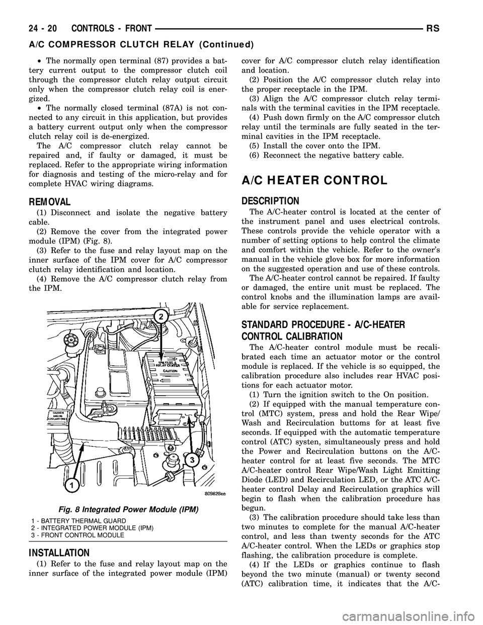
module (IPM) (Fig. 8).
(3) Refer to the fuse and relay layout map on the
inner surface of the IPM cover for A/C compressor
clutch relay identification and location.
(4) Remove the A/C compressor clutch relay from
the IPM.
INSTALLATION
(1) Refer to the fuse and relay layout map on the
inner surface of the integrated power module (IPM)cover for A/C compressor clutch relay identification
and location.
(2) Position the A/C compressor clutch relay into
the proper receptacle in the IPM.
(3) Align the A/C compressor clutch relay termi-
nals with the terminal cavities in the IPM receptacle.
(4) Push down firmly on the A/C compressor clutch
relay until the terminals are fully seated in the ter-
minal cavities in the IPM receptacle.
(5) Install the cover onto the IPM.
(6) Reconnect the negative battery cable.
A/C HEATER CONTROL
DESCRIPTION
The A/C-heater control is located at the center of
the instrument panel and uses electrical controls.
These controls provide the vehicle operator with a
number of setting options to help control the climate
and comfort within the vehicle. Refer to the owner's
manual in the vehicle glove box for more information
on the suggested operation and use of these controls.
The A/C-heater control cannot be repaired. If faulty
or damaged, the entire unit must be replaced. The
control knobs and the illumination lamps are avail-
able for service replacement.
STANDARD PROCEDURE - A/C-HEATER
CONTROL CALIBRATION
The A/C-heater control module must be recali-
brated each time an actuator motor or the control
module is replaced. If the vehicle is so equipped, the
calibration procedure also includes rear HVAC posi-
tions for each actuator motor.
(1) Turn the ignition switch to the On position.
(2) If equipped with the manual temperature con-
trol (MTC) system, press and hold the Rear Wipe/
Wash and Recirculation buttoms for at least five
seconds. If equipped with the automatic temperature
control (ATC) systen, simultaneously press and hold
the Power and Recirculation buttons on the A/C-
heater control for at least five seconds. The MTC
A/C-heater control Rear Wipe/Wash Light Emitting
Diode (LED) and Recirculation LED, or the ATC A/C-
heater control Delay and Recirculation graphics will
begin to flash when the calibration procedure has
begun.
(3) The calibration procedure should take less than
two minutes to complete for the manual A/C-heater
control, and less than twenty seconds for the ATC
A/C-heater control. When the LEDs or graphics stop
flashing, the calibration procedure is complete.
(4) If the LEDs or graphics continue to flash
beyond the two minute (manual) or twenty second
(ATC) calibration time, it indicates that the A/C-
Fig. 8 Integrated Power Module (IPM)
1 - BATTERY THERMAL GUARD
2 - INTEGRATED POWER MODULE (IPM)
3 - FRONT CONTROL MODULE
24 - 20 CONTROLS - FRONTRS
A/C COMPRESSOR CLUTCH RELAY (Continued)