thermostat CHRYSLER VOYAGER 2004 User Guide
[x] Cancel search | Manufacturer: CHRYSLER, Model Year: 2004, Model line: VOYAGER, Model: CHRYSLER VOYAGER 2004Pages: 2585, PDF Size: 62.54 MB
Page 361 of 2585
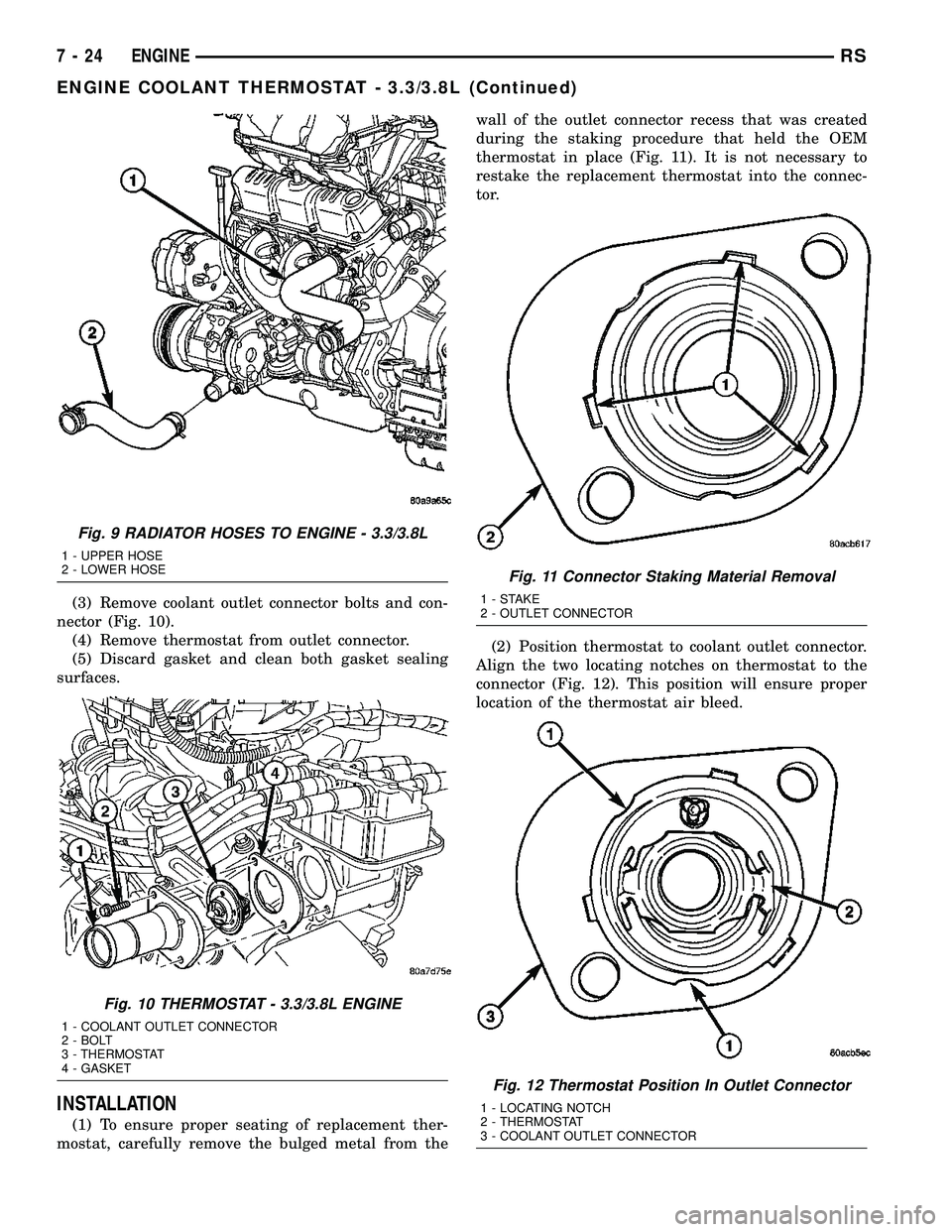
(3) Remove coolant outlet connector bolts and con-
nector (Fig. 10).
(4) Remove thermostat from outlet connector.
(5) Discard gasket and clean both gasket sealing
surfaces.
INSTALLATION
(1) To ensure proper seating of replacement ther-
mostat, carefully remove the bulged metal from thewall of the outlet connector recess that was created
during the staking procedure that held the OEM
thermostat in place (Fig. 11). It is not necessary to
restake the replacement thermostat into the connec-
tor.
(2) Position thermostat to coolant outlet connector.
Align the two locating notches on thermostat to the
connector (Fig. 12). This position will ensure proper
location of the thermostat air bleed.
Fig. 9 RADIATOR HOSES TO ENGINE - 3.3/3.8L
1 - UPPER HOSE
2 - LOWER HOSE
Fig. 10 THERMOSTAT - 3.3/3.8L ENGINE
1 - COOLANT OUTLET CONNECTOR
2 - BOLT
3 - THERMOSTAT
4 - GASKET
Fig. 11 Connector Staking Material Removal
1-STAKE
2 - OUTLET CONNECTOR
Fig. 12 Thermostat Position In Outlet Connector
1 - LOCATING NOTCH
2 - THERMOSTAT
3 - COOLANT OUTLET CONNECTOR
7 - 24 ENGINERS
ENGINE COOLANT THERMOSTAT - 3.3/3.8L (Continued)
Page 362 of 2585
(3) Position a new gasket over the thermostat and
connector making sure thermostat is in proper posi-
tion and in the recess provided.
(4) Install thermostat and connector assembly to
the intake manifold (Fig. 10). Tighten bolts to 28
N´m (250 in. lbs.).
(5) Install the radiator upper hose to coolant outlet
connector (Fig. 9).
(6) Refill the cooling system to the proper level.
(Refer to 7 - COOLING - STANDARD PROCEDURE)
RADIATOR
REMOVAL
(1) Disconnect negative cable from battery.
(2) Remove radiator upper crossmember support.
(Refer to 23 - BODY/EXTERIOR/GRILLE OPENING
REINFORCEMENT - REMOVAL)
WARNING: DO NOT REMOVE THE CYLINDER
BLOCK PLUG OR THE RADIATOR DRAINCOCK
WITH THE SYSTEM HOT AND UNDER PRESSURE
BECAUSE SERIOUS BURNS FROM COOLANT CAN
OCCUR.
(3) Drain the cooling system. (Refer to 7 - COOL-
ING - STANDARD PROCEDURE)
(4) Remove the radiator fans. (Refer to 7 - COOL-
ING/ENGINE/RADIATOR FAN - REMOVAL)
(5) Disconnect coolant reserve/recovery hose.
(6) Remove vapor purge solenoid from mounting
bracket.
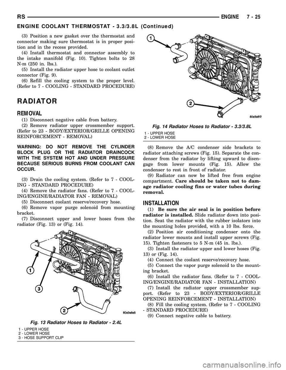
(7) Disconnect upper and lower hoses from the
radiator (Fig. 13) or (Fig. 14).(8) Remove the A/C condenser side brackets to
radiator attaching screws (Fig. 15). Separate the con-
denser from the radiator by lifting upward to disen-
gage from lower mounts (Fig. 15). Allow the
condenser to rest in front of radiator.
(9) Radiator can now be lifted free from engine
compartment.Care should be taken not to dam-
age radiator cooling fins or water tubes during
removal.
INSTALLATION
(1)Be sure the air seal is in position before
radiator is installed.Slide radiator down into posi-
tion. Seat the radiator with the rubber isolators into
the mounting holes provided, with a 10 lbs. force.
(2) Position air conditioning condenser onto the
radiator lower mounts and install upper screws (Fig.
15). Tighten fasteners to 5 N´m (45 in. lbs.).
(3) Install the radiator upper and lower hoses (Fig.
13) or (Fig. 14).
(4) Connect the coolant reserve/recovery hose.
(5) Connect the vapor purge solenoid to the mount-
ing bracket.
(6) Install the radiator fans. (Refer to 7 - COOL-
ING/ENGINE/RADIATOR FAN - INSTALLATION)
(7) Install the radiator upper crossmember sup-
port. (Refer to 23 - BODY/EXTERIOR/GRILLE
OPENING REINFORCEMENT - INSTALLATION)
(8) Fill the cooling system. (Refer to 7 - COOLING
- STANDARD PROCEDURE)
(9) Connect negative cable to battery.
Fig. 13 Radiator Hoses to Radiator - 2.4L
1 - UPPER HOSE
2 - LOWER HOSE
3 - HOSE SUPPORT CLIP
Fig. 14 Radiator Hoses to Radiator - 3.3/3.8L
1 - UPPER HOSE
2 - LOWER HOSE
RSENGINE7-25
ENGINE COOLANT THERMOSTAT - 3.3/3.8L (Continued)
Page 1322 of 2585
²Excessive steam (white smoke) emitting from
exhaust
²Coolant foaming
CYLINDER-TO-CYLINDER LEAKAGE TEST
To determine if an engine cylinder head gasket is
leaking between adjacent cylinders, follow the proce-
dures in Cylinder Compression Pressure Test (Refer
to 9 - ENGINE - DIAGNOSIS AND TESTING). An
engine cylinder head gasket leaking between adja-
cent cylinders will result in approximately a 50±70%
reduction in compression pressure.
CYLINDER-TO-WATER JACKET LEAKAGE TEST
WARNING: USE EXTREME CAUTION WHEN THE
ENGINE IS OPERATING WITH COOLANT PRES-
SURE CAP REMOVED.
VISUAL TEST METHOD
With the engine cool, remove the coolant pressure
cap. Start the engine and allow it to warm up until
thermostat opens.
If a large combustion/compression pressure leak
exists, bubbles will be visible in the coolant.COOLING SYSTEM TESTER METHOD
WARNING: WITH COOLING SYSTEM TESTER IN
PLACE, PRESSURE WILL BUILD UP FAST. EXCES-
SIVE PRESSURE BUILT UP, BY CONTINUOUS
ENGINE OPERATION, MUST BE RELEASED TO A
SAFE PRESSURE POINT. NEVER PERMIT PRES-
SURE TO EXCEED 138 kPa (20 psi).
Install Cooling System Tester 7700 or equivalent to
pressure cap neck. Start the engine and observe the
tester's pressure gauge. If gauge pulsates with every
power stroke of a cylinder a combustion pressure
leak is evident.
CHEMICAL TEST METHOD
Combustion leaks into the cooling system can also
be checked by using Bloc-Chek Kit C-3685-A or
equivalent. Perform test following the procedures
supplied with the tool kit.
REMOVAL - CYLINDER HEAD
(1) Perform fuel system pressure release procedure
before attempting any repairs.(Refer to 14 -
FUEL SYSTEM/FUEL DELIVERY - SPECIFICA-
TIONS)
(2) Disconnect battery negative cable.
(3) Drain cooling system. (Refer to 7 - COOLING -
STANDARD PROCEDURE)
(4) Remove air filter housing and inlet tube.
(5) Remove upper intake manifold. (Refer to 9 -
ENGINE/MANIFOLDS/INTAKE MANIFOLD -
REMOVAL)
(6) Remove heater tube support bracket from cyl-
inder head.
(7) Disconnect radiator upper and heater supply
hoses from intake manifold water outlet connections.
(8) Remove accessory drive belts. (Refer to 7 -
COOLING/ACCESSORY DRIVE/DRIVE BELTS -
REMOVAL)
(9) Raise vehicle and remove exhaust pipe from
manifold.
(10) Remove power steering pump reservoir and
line support bracket from lower intake manifold and
set aside. Do not disconnect lines.
(11) Remove ignition coil and wires from engine.
(12) Disconnect cam sensor and fuel injector wir-
ing connectors.
(13) Remove timing belt and camshaft sprockets.
(Refer to 9 - ENGINE/VALVE TIMING/TIMING
BELT/CHAIN AND SPROCKETS - REMOVAL)
(14) Remove timing belt idler pulley and rear tim-
ing belt cover. (Refer to 9 - ENGINE/VALVE TIM-
ING/TIMING BELT / CHAIN COVER(S) -
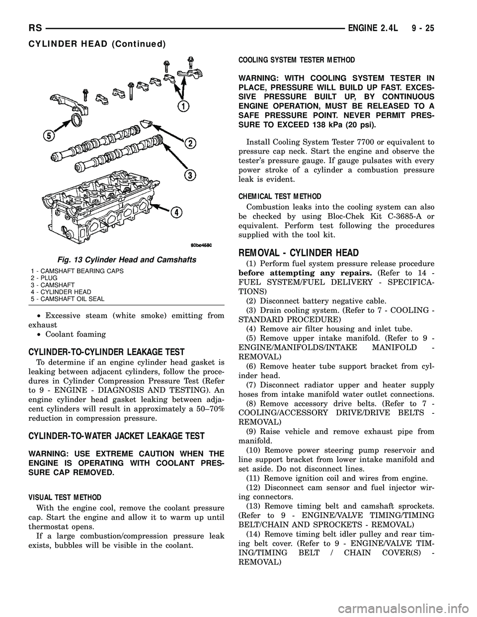
REMOVAL)Fig. 13 Cylinder Head and Camshafts
1 - CAMSHAFT BEARING CAPS
2 - PLUG
3 - CAMSHAFT
4 - CYLINDER HEAD
5 - CAMSHAFT OIL SEAL
RSENGINE 2.4L9-25
CYLINDER HEAD (Continued)
Page 1396 of 2585
AIR CLEANER HOUSING
REMOVAL
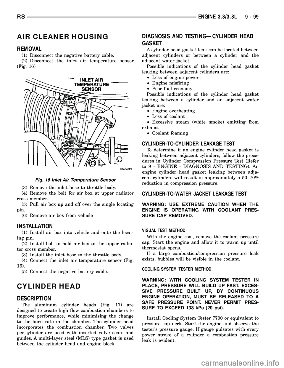
(1) Disconnect the negative battery cable.
(2) Disconnect the inlet air temperature sensor
(Fig. 16).
(3) Remove the inlet hose to throttle body.
(4) Remove the bolt for air box at upper radiator
cross member.
(5) Pull air box up and off over the single locating
pin.
(6) Remove air box from vehicle
INSTALLATION
(1) Install air box into vehicle and onto the locat-
ing pin.
(2) Install bolt to hold air box to the upper radia-
tor cross member.
(3) Install the inlet hose to the throttle body.
(4) Connect the inlet air temperature sensor (Fig.
16).
(5) Connect the negative battery cable.
CYLINDER HEAD
DESCRIPTION
The aluminum cylinder heads (Fig. 17) are
designed to create high flow combustion chambers to
improve performance, while minimizing the change
to the burn rate in the chamber. The cylinder head
incorporates the combustion chamber. Two valves
per-cylinder are used with inserted valve seats and
guides. A multi-layer steel (MLS) type gasket is used
between the cylinder head and engine block.
DIAGNOSIS AND TESTINGÐCYLINDER HEAD
GASKET
A cylinder head gasket leak can be located between
adjacent cylinders or between a cylinder and the
adjacent water jacket.
Possible indications of the cylinder head gasket
leaking between adjacent cylinders are:
²Loss of engine power
²Engine misfiring
²Poor fuel economy
Possible indications of the cylinder head gasket
leaking between a cylinder and an adjacent water
jacket are:
²Engine overheating
²Loss of coolant
²Excessive steam (white smoke) emitting from
exhaust
²Coolant foaming
CYLINDER-TO-CYLINDER LEAKAGE TEST
To determine if an engine cylinder head gasket is
leaking between adjacent cylinders, follow the proce-
dures in Cylinder Compression Pressure Test (Refer
to 9 - ENGINE - DIAGNOSIS AND TESTING). An
engine cylinder head gasket leaking between adja-
cent cylinders will result in approximately a 50±70%
reduction in compression pressure.
CYLINDER-TO-WATER JACKET LEAKAGE TEST
WARNING: USE EXTREME CAUTION WHEN THE
ENGINE IS OPERATING WITH COOLANT PRES-
SURE CAP REMOVED.
VISUAL TEST METHOD
With the engine cool, remove the coolant pressure
cap. Start the engine and allow it to warm up until
thermostat opens.
If a large combustion/compression pressure leak
exists, bubbles will be visible in the coolant.
COOLING SYSTEM TESTER METHOD
WARNING: WITH COOLING SYSTEM TESTER IN
PLACE, PRESSURE WILL BUILD UP FAST. EXCES-
SIVE PRESSURE BUILT UP, BY CONTINUOUS
ENGINE OPERATION, MUST BE RELEASED TO A
SAFE PRESSURE POINT. NEVER PERMIT PRES-
SURE TO EXCEED 138 kPa (20 psi).
Install Cooling System Tester 7700 or equivalent to
pressure cap neck. Start the engine and observe the
tester's pressure gauge. If gauge pulsates with every
power stroke of a cylinder a combustion pressure
leak is evident.
Fig. 16 Inlet Air Temperature Sensor
RSENGINE 3.3/3.8L9-99
Page 1441 of 2585
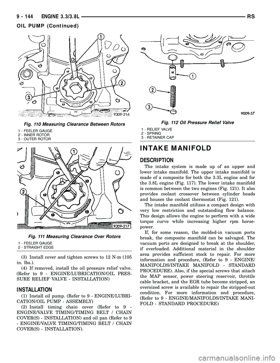
(3) Install cover and tighten screws to 12 N´m (105
in. lbs.).
(4) If removed, install the oil pressure relief valve.
(Refer to 9 - ENGINE/LUBRICATION/OIL PRES-
SURE RELIEF VALVE - INSTALLATION)
INSTALLATION
(1) Install oil pump. (Refer to 9 - ENGINE/LUBRI-
CATION/OIL PUMP - ASSEMBLY)
(2) Install timing chain cover (Refer to 9 -
ENGINE/VALVE TIMING/TIMING BELT / CHAIN
COVER(S) - INSTALLATION) and oil pan (Refer to 9
- ENGINE/VALVE TIMING/TIMING BELT / CHAIN
COVER(S) - INSTALLATION).
INTAKE MANIFOLD
DESCRIPTION
The intake system is made up of an upper and
lower intake manifold. The upper intake manifold is
made of a composite for both the 3.3L engine and for
the 3.8L engine (Fig. 117). The lower intake manifold
is common between the two engines (Fig. 121). It also
provides coolant crossover between cylinder heads
and houses the coolant thermostat (Fig. 121).
The intake manifold utilizes a compact design with
very low restriction and outstanding flow balance.
This design allows the engine to perform with a wide
torque curve while increasing higher rpm horse-
power.
If, for some reason, the molded-in vacuum ports
break, the composite manifold can be salvaged. The
vacuum ports are designed to break at the shoulder,
if overloaded. Additional material in the shoulder
area provides sufficient stock to repair. For more
information and procedure, (Refer to 9 - ENGINE/
MANIFOLDS/INTAKE MANIFOLD - STANDARD
PROCEDURE). Also, if the special screws that attach
the MAP sensor, power steering reservoir, throttle
cable bracket, and the EGR tube become stripped, an
oversized screw is available to repair the stripped-out
condition. For more information and procedure,
(Refer to 9 - ENGINE/MANIFOLDS/INTAKE MANI-
FOLD - STANDARD PROCEDURE)
Fig. 110 Measuring Clearance Between Rotors
1 - FEELER GAUGE
2 - INNER ROTOR
3 - OUTER ROTOR
Fig. 111 Measuring Clearance Over Rotors
1 - FEELER GAUGE
2 - STRAIGHT EDGE
Fig. 112 Oil Pressure Relief Valve
1 - RELIEF VALVE
2 - SPRING
3 - RETAINER CAP
9 - 144 ENGINE 3.3/3.8LRS
OIL PUMP (Continued)
Page 1472 of 2585
CYLINDER-TO-WATER JACKET LEAKAGE TEST
WARNING: USE EXTREME CAUTION WHEN THE
ENGINE IS OPERATING WITH COOLANT PRES-
SURE CAP REMOVED.
VISUAL TEST METHOD
With the engine cool, remove the coolant pressure
cap. Start the engine and allow it to warm up until
thermostat opens.
If a large combustion/compression pressure leak
exists, bubbles will be visible in the coolant.
COOLING SYSTEM TESTER METHOD
WARNING: WITH COOLING SYSTEM TESTER IN
PLACE, PRESSURE WILL BUILD UP FAST. EXCES-
SIVE PRESSURE BUILT UP, BY CONTINUOUS
ENGINE OPERATION, MUST BE RELEASED TO A
SAFE PRESSURE POINT. NEVER PERMIT PRES-
SURE TO EXCEED 138 kPa (20 psi).
Install Cooling System Tester 7700 or equivalent to
pressure cap neck. Start the engine and observe the
tester's pressure gauge. If gauge pulsates with every
power stroke of a cylinder a combustion pressure
leak is evident.
CHEMICAL TEST METHOD
Combustion leaks into the cooling system can also
be checked by using Bloc-Chek Kit C-3685-A or
equivalent. Perform test following the procedures
supplied with the tool kit.
REMOVAL - CYLINDER HEAD
(1) Drain the cooling system. (Refer to 7 - COOL-
ING - STANDARD PROCEDURE)
(2) Disconnect negative cable from battery.
(3) Remove upper and lower intake manifolds.
(Refer to 9 - ENGINE/MANIFOLDS/INTAKE MANI-
FOLD - REMOVAL)
WARNING: INTAKE MANIFOLD GASKET IS MADE
OF VERY THIN METAL AND MAY CAUSE PER-
SONAL INJURY, HANDLE WITH CARE.
(4) Remove the cylinder head covers. (Refer to 9 -
ENGINE/CYLINDER HEAD/CYLINDER HEAD
COVER(S) - REMOVAL)
(5) Remove the spark plugs from cylinder head.
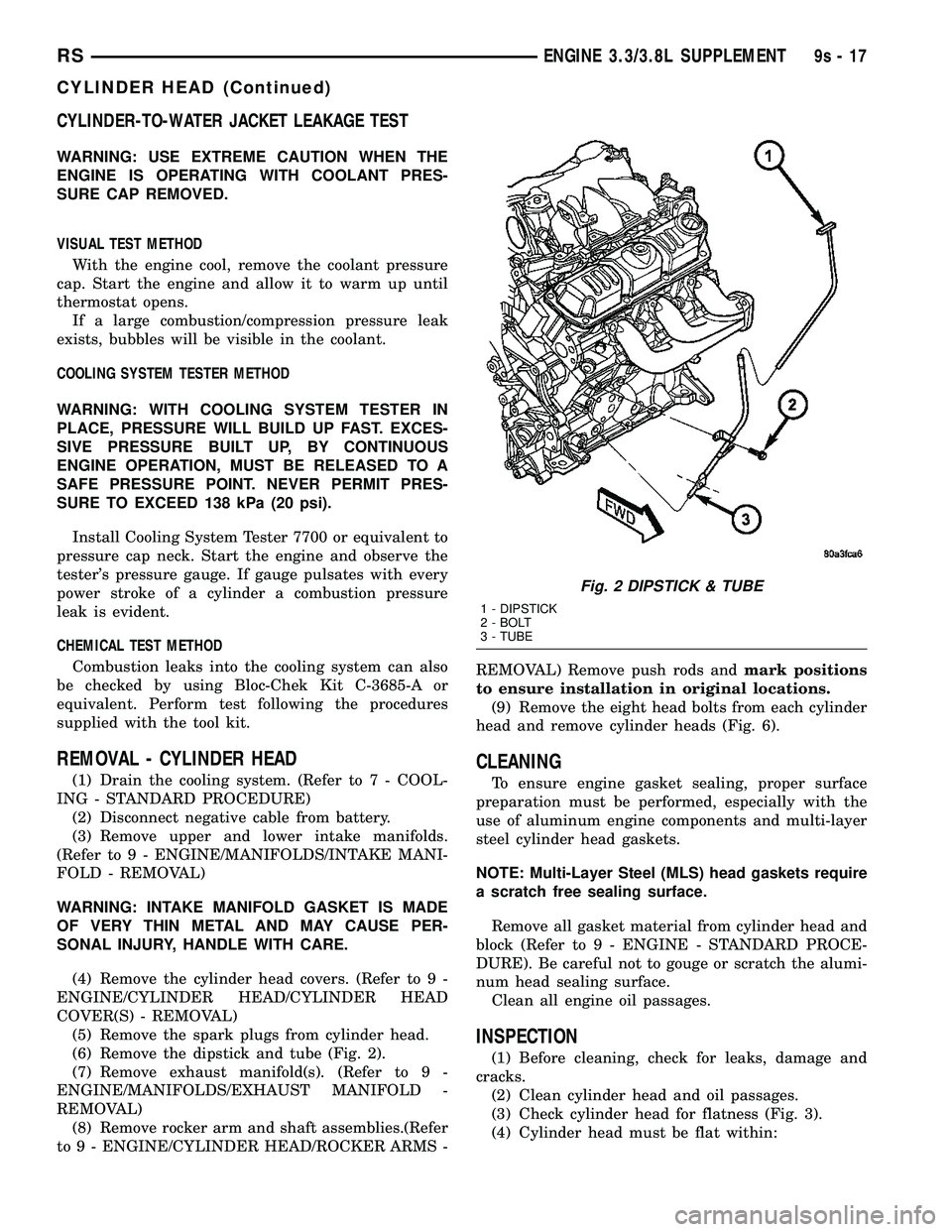
(6) Remove the dipstick and tube (Fig. 2).
(7) Remove exhaust manifold(s). (Refer to 9 -
ENGINE/MANIFOLDS/EXHAUST MANIFOLD -
REMOVAL)
(8) Remove rocker arm and shaft assemblies.(Refer
to 9 - ENGINE/CYLINDER HEAD/ROCKER ARMS -REMOVAL) Remove push rods andmark positions
to ensure installation in original locations.
(9) Remove the eight head bolts from each cylinder
head and remove cylinder heads (Fig. 6).
CLEANING
To ensure engine gasket sealing, proper surface
preparation must be performed, especially with the
use of aluminum engine components and multi-layer
steel cylinder head gaskets.
NOTE: Multi-Layer Steel (MLS) head gaskets require
a scratch free sealing surface.
Remove all gasket material from cylinder head and
block (Refer to 9 - ENGINE - STANDARD PROCE-
DURE). Be careful not to gouge or scratch the alumi-
num head sealing surface.
Clean all engine oil passages.
INSPECTION
(1) Before cleaning, check for leaks, damage and
cracks.
(2) Clean cylinder head and oil passages.
(3) Check cylinder head for flatness (Fig. 3).
(4) Cylinder head must be flat within:
Fig. 2 DIPSTICK & TUBE
1 - DIPSTICK
2 - BOLT
3 - TUBE
RSENGINE 3.3/3.8L SUPPLEMENT9s-17
CYLINDER HEAD (Continued)
Page 2396 of 2585
HEATING & AIR CONDITIONING
TABLE OF CONTENTS
page page
HEATING & AIR CONDITIONING
DESCRIPTION
DESCRIPTION - ENGINE COOLING
SYSTEM REQUIREMENTS...............1
DESCRIPTION - HEATER AND AIR
CONDITIONER........................1
DESCRIPTION - SINGLE ZONE...........2
DESCRIPTION - DUAL ZONE.............2
DESCRIPTION - MANUAL THREE ZONE.....2
DESCRIPTION - AUTOMATIC THREE ZONE . . 3
OPERATION
OPERATION - HEATER AND AIR
CONDITIONER........................4
OPERATION - SINGLE ZONE.............4
OPERATION - DUAL ZONE...............5
OPERATION - MANUAL THREE ZONE......5
OPERATION - THREE ZONE ATC..........5DIAGNOSIS AND TESTING
DIAGNOSIS AND TESTING - A/C COOL
DOWN TEST..........................6
DIAGNOSIS AND TESTING - A/C
PERFORMANCE TEST..................7
DIAGNOSIS AND TESTING - HEATER
PERFORMANCE TEST.................10
SPECIFICATIONS
A/C SYSTEM.........................11
CONTROLS - FRONT.....................14
CONTROLS - REAR......................34
DISTRIBUTION - FRONT...................43
DISTRIBUTION - REAR....................56
PLUMBING - FRONT.....................64
PLUMBING - REAR......................97
CABIN HEATER........................112
HEATING & AIR
CONDITIONING
DESCRIPTION
DESCRIPTION - ENGINE COOLING SYSTEM
REQUIREMENTS
To maintain the performance level of the heating,
ventilation and air conditioning (HVAC) system, the
engine cooling system must be properly maintained.
The use of a bug screen is not recommended. Any
obstructions in front of the radiator or condenser will
reduce the performance of the air conditioning and
engine cooling systems.
The engine cooling system includes the radiator,
thermostat, radiator hoses and the engine coolant
pump. Refer to Cooling for more information before
opening or attempting any service to the engine cool-
ing system.
DESCRIPTION - HEATER AND AIR
CONDITIONER
A manually controlled single zone type heating-air
conditioning system, manually controlled dual zone
type heating-air conditioning system, manually con-
trolled three zone type heating-air conditioning sys-
tem or an automatic controlled three zone typeheating-air conditioning system is available on this
model.
All vehicles are equipped with a common heater,
ventilation and air conditioning (HVAC) housing (Fig.
1). The system combines air conditioning, heating,
and ventilating capabilities in a single unit housing
mounted within the passenger compartment under
the instrument panel. The HVAC housing includes:
²Blower motor
²Blower motor resistor block or power module
(depending on application)
²Heater core
²Evaporator coil
²Blend door and actuator
²Mode door and actuator
²Recirculation door and actuator
Based upon the system and mode selected, condi-
tioned air can exit the HVAC housing through one or
a combination of the three main housing outlets:
defrost, panel or floor. The defrost and panel outlets
are located on the top of the housing and the floor
outlet is located on the bottom of the housing. Once
the conditioned air exits the unit housing, it is fur-
ther directed through molded plastic ducts to the var-
ious outlets in the vehicle interior. These outlets and
their locations are as follows:
²Defroster Outlet- A single large defroster out-
let is located in the center of the instrument panel
top cover, near the base of the windshield.
²Side Window Demister Outlets- There are
two side window demister outlets, one is located at
RSHEATING & AIR CONDITIONING24-1
Page 2480 of 2585
INSTALLATION
INSTALLATION - HEATER CORE TUBES
(1) Remove the plugs or tape from both heater core
tube fittings and both heater core ports.
(2) Position the heater core tubes and sealing plate
as a unit beneath the instrument panel.
(3) Align the engine compartment ends of both
heater core tubes with the openings in the dash
panel seal and push them simultaneously forward
through the seal far enough to engage the heater
core ends of the tubes with the heater core supply
and return ports.
(4) Position both heater core tubes and the sealing
plate simultaneously to the heater core supply and
return ports.
NOTE: The heater core tubes each have a slot that
must be indexed to a location tab within each of the
heater core ports. Adjust the position of the tubes
as required so that the sealing plate fits flush
against the heater core supply and return ports,
which indicates that the tubes are properly indexed.
(5) Index both heater core tubes to the heater core
ports.
(6) Install the screw that secures the heater core
tube sealing plate to the heater core supply and
return ports. Tighten the screw to 3 N´m (27 in. lbs.).
(7) Install the silencer under the driver side end of
the instrument panel.
(8) Connect the heater hoses to the heater hose
tubes (Refer to 24 - HEATING & AIR CONDITION-
ING/PLUMBING/HEATER INLET HOSE - INSTAL-
LATION) and(Refer to 24 - HEATING & AIR
CONDITIONING/PLUMBING/HEATER RETURN
HOSE - INSTALLATION).
(9) Reconnect the battery negative cable.
(10) Refill the engine cooling system (Refer to 7 -
COOLING - STANDARD PROCEDURE - COOLING
SYSTEM REFILL).
INSTALLATION - HEATER CORE
(1) While pushing the brake pedal downward and
pulling the accelerator pedal upward far enough for
clearance, slide the heater core into the distribution
housing.
(2) Install the two screws that secure the heater
core mounting plate to the distribution housing.
Tighten the screws to 2 N´m (17 in. lbs.).
(3) Install the heater core tubes (Refer to 24 -
HEATING & AIR CONDITIONING/PLUMBING/
HEATER CORE - INSTALLATION).
(4) Reconnect the power brake booster input rod
(push rod) to the pin on the brake pedal arm (Referto 5 - BRAKES/HYDRAULIC/MECHANICAL/
POWER BRAKE BOOSTER - INSTALLATION).
(5) Reinstall the brake lamp switch into its mount-
ing bracket (Refer to 8 - ELECTRICAL/LAMPS/
LIGHTING - EXTERIOR/BRAKE LAMP SWITCH -
INSTALLATION).
(6) Reinstall the silencer boot around the base of
the lower steering shaft on the dash panel.
(7) Reconnect the battery negative cable.
(8) Refill the engine cooling system (Refer to 7 -
COOLING - STANDARD PROCEDURE - COOLING
SYSTEM REFILL).
(9) Operate system for two thermostat cycles to
assure the elimination of any air that may be
trapped within the cooling system.
HEATER INLET HOSE
REMOVAL
WARNING: REFER TO THE APPLICABLE WARN-
INGS AND CAUTIONS FOR THIS SYSTEM BEFORE
PERFORMING THE FOLLOWING OPERATION (Refer
to 24 - HEATING & AIR CONDITIONING/PLUMBING -
WARNING).
NOTE: The heater inlet hose is constructed from
formed steel tubing and rubber hoses. Depending
on application, the ends are secured to the heater
core, engine oil cooler or the engine by spring ten-
sion clamps.
(1) Drain the engine cooling system (Refer to 7 -
COOLING - STANDARD PROCEDURE - COOLING
SYSTEM DRAIN).
(2) Using spring tension clamp pliers, compress
and slide the clamps off of each end of the hose being
removed (Fig. 17), (Fig. 18) or (Fig. 19).
CAUTION:
DO NOT apply excessive pressure on heater tubes
or connections when removing heater hoses.
Excessive pressure may damage or deform the
tubes/heater core, causing an engine coolant leak.
(3) Disconnect each hose end by carefully twisting
the hose back and forth on the tube or nipple, while
gently pulling it away from the end of the tube or
nipple.
NOTE:
Replacement of the heater inlet hoses will be
required if the hose ends are cut for removal.
(4) If necessary, carefully cut the hose end and
peel the hose off of the tube or nipple.
RSPLUMBING - FRONT24-85
HEATER CORE (Continued)
Page 2497 of 2585
(7) Refill the engine cooling system (Refer to 7 -
COOLING - STANDARD PROCEDURE - COOLING
SYSTEM REFILL).
THERMAL CYCLING
If the rear heater core was emptied and was not
pre-filled, it will be necessary to thermal cycle the
vehicle at least two times to ensure that the rear
heater core is properly filled.
(1) Refill the engine cooling system (Refer to 7 -
COOLING - STANDARD PROCEDURE - COOLING
SYSTEM REFILL).
(2) Start the engine and allow it to operate until
the thermostat opens.
(3) Turn the engine off and allow it to cool.
(4) With the engine cold and not running, check
and top off the engine coolant level as necessary
(Refer to 7 - COOLING - STANDARD PROCEDURE
- COOLANT LEVEL CHECK) and (Refer to 7 -
COOLING - STANDARD PROCEDURE - COOLANT
- ADDING).
(5) Start the engine and allow it to operate until
the thermostat opens again.
(6) Turn the engine off and allow it to cool down
again.
(7) With the engine cold and not running, check
and top off the engine coolant level as necessary
(Refer to 7 - COOLING - STANDARD PROCEDURE
- COOLANT LEVEL CHECK) and (Refer to 7 -
COOLING - STANDARD PROCEDURE - COOLANT
- ADDING).
(8) Check the performance of the rear heater.
Refer to REAR HEATER PERFORMANCE CHECK.
REAR HEATER PERFORMANCE CHECK
Successful completion of the rear heater perfor-
mance check will confirm that the rear heater core is
properly filled with engine coolant. If the check is not
successful, either there is still air trapped in the rear
heater core or the rear heater plumbing is restricted.
This check should be performed with the vehicle in a
shop where the ambient temperature is about 21É C
(70É F).
(1) Start the engine and allow it to idle until it
warms up to normal operating temperature.
(2) Adjust the heater-A/C controls so that the front
heater is turned Off, the rear heater is set for full
Heat, and the rear blower motor is at its highest
speed setting.
(3) Use an accurate test thermometer to measure
the temperature of the air being discharged from the
rear heater outlet located at the base of the right
C-pillar.
(4) Proper discharge air temperature readings
should be from 57É to 63É C (135É to 145É F).REMOVAL
WARNING: REFER TO THE APPLICABLE WARN-
INGS AND CAUTIONS FOR THIS SYSTEM BEFORE
PERFORMING THE FOLLOWING OPERATION (Refer
to 24 - HEATING & AIR CONDITIONING/PLUMBING
FRONT - WARNING - HEATER PLUMBING).
(1) Drain the engine cooling system (Refer to 7 -
COOLING - STANDARD PROCEDURE - COOLING
SYSTEM DRAIN).
(2) Remove the right quarter trim panel and right
D-pillar trim panel from the quarter inner panel
(Refer to 23 - BODY/INTERIOR/QUARTER TRIM
PANEL - REMOVAL).
(3) Remove the rear heater distribution duct from
the right quarter inner panel (Refer to 24 - HEAT-
ING & AIR CONDITIONING/DISTRIBUTION -
REAR/REAR HEATER DISTRIBUTION DUCT -
REMOVAL).
(4) Remove the screw that secures the back of the
rear HVAC housing to the right D-pillar.
(5) Remove the screw that secures the front of the
rear HVAC housing to the right quarter inner panel.
(6) Take the proper precautions to protect the car-
peting below the rear heater core from spilled engine
coolant and have absorbent toweling readily avail-
able to mop up any spills.
(7) Disconnect the heater hoses at the rear heater
core (Refer to 24 - HEATING & AIR CONDITION-
ING/PLUMBING - REAR/HEATER HOSE -
REMOVAL).
(8) Install plugs in, or tape over the opened heater
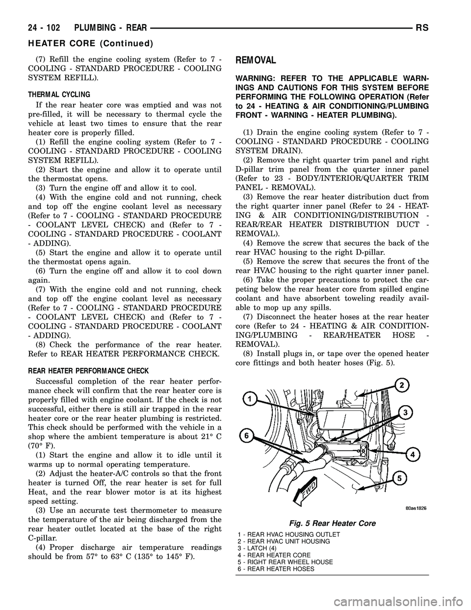
core fittings and both heater hoses (Fig. 5).
Fig. 5 Rear Heater Core
1 - REAR HVAC HOUSING OUTLET
2 - REAR HVAC UNIT HOUSING
3 - LATCH (4)
4 - REAR HEATER CORE
5 - RIGHT REAR WHEEL HOUSE
6 - REAR HEATER HOSES
24 - 102 PLUMBING - REARRS
HEATER CORE (Continued)
Page 2552 of 2585
COOLANT TEMPERATURE SENSOR -
3.3/3.8L - DESCRIPTION, ENGINE.........7-21
COOLANT TEMPERATURE SENSOR -
3.3/3.8L - INSTALLATION, ENGINE........7-22
COOLANT TEMPERATURE SENSOR -
3.3/3.8L - REMOVAL, ENGINE............7-21
COOLANT THERMOSTAT - 2.4L -
INSTALLATION, ENGINE................7-23
COOLANT THERMOSTAT - 2.4L -
REMOVAL, ENGINE....................7-23
COOLANT THERMOSTAT - 3.3/3.8L -
INSTALLATION, ENGINE................7-24
COOLANT THERMOSTAT - 3.3/3.8L -
REMOVAL, ENGINE....................7-23
COOLANT THERMOSTAT - DESCRIPTION,
ENGINE.............................7-22
COOLANT THERMOSTAT - DIAGNOSIS
AND TESTING, ENGINE.................7-23
COOLANT THERMOSTAT - OPERATION,
ENGINE.............................7-22
COOLER - DESCRIPTION, FLUID.........19-44
COOLER - DESCRIPTION,
TRANSMISSION OIL...................7-37
COOLER - INSPECTION, TRANSMISSION
OIL ................................7-37
COOLER - INSTALLATION, FLUID........19-45
COOLER - INSTALLATION,
TRANSMISSION OIL...................7-37
COOLER & LINES - DESCRIPTION, OIL . . . 9-138
COOLER & LINES - INSTALLATION, OIL . . . 9-138
COOLER & LINES - OPERATION, OIL.....9-138
COOLER & LINES - REMOVAL, OIL........9-138
COOLER - OPERATION, FLUID..........19-44
COOLER - REMOVAL, FLUID............19-44
COOLER - REMOVAL, TRANSMISSION
OIL ................................7-37
COOLER LINES - INSTALLATION,
TRANSMISSION OIL...................7-38
COOLER LINES - REMOVAL,
TRANSMISSION OIL...................7-38
COOLING SYSTEM - DESCRIPTION........7-1
COOLING SYSTEM - DIAGNOSIS AND
TESTING, ENGINE.....................7-14
COOLING SYSTEM - OPERATION..........7-2
COOLING SYSTEM AERATION -
DIAGNOSIS AND TESTING...............7-3
COOLING SYSTEM DEAERATION -
DIAGNOSIS AND TESTING...............7-4
COOLING SYSTEM DRAINING -
STANDARD PROCEDURE.................7-4
COOLING SYSTEM FILLING - STANDARD
PROCEDURE..........................7-5
COOLING SYSTEM FLOW CHECK -
DIAGNOSIS AND TESTING...............7-3
COOLING SYSTEM LEAK TEST -
DIAGNOSIS AND TESTING...............7-2
COOLING SYSTEM PRESSURE CAP
TESTING - DIAGNOSIS AND TESTING......7-27
COOLING SYSTEM REQUIREMENTS -
DESCRIPTION, ENGINE.................24-1
COOLING SYSTEM, SPECIAL TOOLS.......7-6
COOLING SYSTEM, WARNING - ENGINE . . 24-65
CORE - DESCRIPTION, HEATER . . . 24-101,24-83
CORE - DESCRIPTION, SERVICE PORT
VALVE .............................24-94
CORE - INSTALLATION, HEATER . . . 24-103,24-85
CORE - INSTALLATION, SERVICE PORT
VALVE .............................24-94
CORE - OPERATION, HEATER.....24-101,24-83
CORE - REMOVAL, HEATER......24-102,24-84
CORE - REMOVAL, SERVICE PORT
VALVE .............................24-94
CORE AND OIL GALLERY PLUGS -
STANDARD PROCEDURE, ENGINE....9-10,9-86
CORE FILLING - STANDARD
PROCEDURE, REAR HEATER...........24-101
CORE TUBES - INSTALLATION, HEATER . . . 24-85
CORE TUBES - REMOVAL, HEATER.......24-83
COUPLER - DESCRIPTION, VISCOUS......3-41
COUPLER - OPERATION, VISCOUS........3-42
COURTESY LAMP - INSTALLATION.......8L-21
COURTESY LAMP - REMOVAL..........8L-21
COVER - CLEANING, CYLINDER HEAD
.....9-31
COVER - DESCRIPTION, SHIFT
.........21-113
COVER - DESCRIPTION, WHEEL
.........22-19
COVER - INSPECTION, CYLINDER HEAD
. . . 9-31
COVER - INSTALLATION, BENCH SEAT
BACK
.............................23-103COVER - INSTALLATION, CYLINDER
HEAD...............................9-31
COVER - INSTALLATION, DRIVER
AIRBAG TRIM........................8O-7
COVER - INSTALLATION, FRONT SEAT
CUSHION SIDE......................23-94
COVER - INSTALLATION, FRONT SEAT
TRACK - REAR......................23-96
COVER - INSTALLATION, FRONT
SEATBACK..........................23-93
COVER - INSTALLATION, INSTRUMENT
PANEL TOP.........................23-69
COVER - INSTALLATION, LOWER
STEERING COLUMN..................23-70
COVER - INSTALLATION, OVER
STEERING COLUMN..................23-70
COVER - INSTALLATION, TIMING CHAIN . . 9-155
COVER - INSTALLATION, WHEEL........22-19
COVER - LEFT - INSTALLATION,
CYLINDER HEAD.....................9-103
COVER - LEFT - REMOVAL, CYLINDER
HEAD..............................9-103
COVER - QUAD BUCKET, 50/50 SPLIT,
BENCH - INSTALLATION, SEAT
CUSHION..........................23-100
COVER - QUAD BUCKET, 50/50 SPLIT,
BENCH - REMOVAL, SEAT CUSHION.....23-100
COVER - REMOVAL, BENCH SEAT BACK . . 23-103
COVER - REMOVAL, CYLINDER HEAD.....9-31
COVER - REMOVAL, DRIVER AIRBAG
TRIM...............................8O-7
COVER - REMOVAL, FRONT SEAT
CUSHION SIDE........................23-94
COVER - REMOVAL, FRONT SEAT TRACK
- REAR............................23-96
COVER - REMOVAL, FRONT SEATBACK . . . 23-93
COVER - REMOVAL, INSTRUMENT
PANEL TOP.........................23-68
COVER - REMOVAL, LOWER STEERING
COLUMN...........................23-70
COVER - REMOVAL, OVER STEERING
COLUMN...........................23-70
COVER - REMOVAL, TIMING CHAIN......9-153
COVER - REMOVAL, WHEEL............22-19
COVER - RIGHT - INSTALLATION,
CYLINDER HEAD.....................9-103
COVER - RIGHT - REMOVAL, CYLINDER
HEAD..............................9-102
COVER AND DISC RUNOUT - DIAGNOSIS
AND TESTING, CLUTCH.................6-6
COVER BACKING PLATE -
INSTALLATION, STEERING COLUMN......23-70
COVER BACKING PLATE - REMOVAL,
STEERING COLUMN..................23-70
COVER BALL BEARING - INSTALLATION,
END ...............................21-10
COVER BALL BEARING - REMOVAL, END . . . 21-9
COVER O-RING - INSTALLATION, REAR . . . 21-20
COVER O-RING - REMOVAL, REAR.......21-19
COVER SEAL - INSTALLATION, END......21-11
COVER SEAL - INSTALLATION, INPUT
SHAFT.............................21-14
COVER SEAL - REMOVAL, END..........21-11
COVER SEAL - REMOVAL, INPUT SHAFT . . 21-13
COVER-LEFT - INSTALLATION, CYLINDER
HEAD..............................9s-20
COVER-LEFT - REMOVAL, CYLINDER
HEAD..............................9s-20
COVER-RIGHT - INSTALLATION,
CYLINDER HEAD.....................9s-19
COVER-RIGHT - REMOVAL, CYLINDER
HEAD..............................9s-19
COVER(S) - DESCRIPTION, CYLINDER
HEAD.........................9-102,9s-19
COVER(S) - INSTALLATION, TIMING
BELT ...............................9-62
COVERS - QUAD BUCKET, 50/50 SPLIT,
BENCH - INSTALLATION, SEAT BACK
HINGE............................23-101
COVERS - QUAD BUCKET, 50/50 SPLIT,
BENCH - REMOVAL, SEAT BACK HINGE . . 23-101
COVER(S) - REMOVAL, TIMING BELT......9-61
COWL GRILLE - INSTALLATION
.........23-51
COWL GRILLE - REMOVAL
.............23-50
COWL TRIM - INSTALLATION
...........23-76
COWL TRIM - REMOVAL
...............23-76
C-PILLAR - INSTALLATION, SEAT BELT
HEIGHT ADJUSTER-BOR
.............8O-13C-PILLAR - REMOVAL, SEAT BELT
HEIGHT ADJUSTER-BOR.............8O-13
C-PILLAR TRIM - INSTALLATION........23-77
C-PILLAR TRIM - REMOVAL............23-77
CRADLE CROSSMEMBER -
DESCRIPTION, FRONT..................13-9
CRADLE CROSSMEMBER THREAD
REPAIR - DESCRIPTION, FRONT..........13-9
CRANK - INSTALLATION, WINDOW.......23-21
CRANK - REMOVAL, WINDOW..........23-21
CRANKSHAFT - INSPECTION.........9-37,9s-7
CRANKSHAFT - INSTALLATION.......9-38,9s-7
CRANKSHAFT - REMOVAL...........9-37,9s-6
CRANKSHAFT END PLAY - STANDARD
PROCEDURE.....................9-36,9s-6
CRANKSHAFT END PLAY - STANDARD
PROCEDURE, MEASURING.............9-125
CRANKSHAFT MAIN BEARINGS -
INSTALLATION.......................9-124
CRANKSHAFT MAIN BEARINGS -
REMOVAL..........................9-124
CRANKSHAFT OIL SEAL - FRONT -
INSTALLATION...................9-127,9-40
CRANKSHAFT OIL SEAL - FRONT -
REMOVAL......................9-127,9-40
CRANKSHAFT OIL SEAL - REAR -
INSTALLATION...................9-129,9-42
CRANKSHAFT OIL SEAL - REAR -
REMOVAL......................9-128,9-41
CRANKSHAFT POSITION SENSOR -
DESCRIPTION.......................14-25
CRANKSHAFT POSITION SENSOR -
OPERATION.........................14-25
CRANKSHAFT POSITION SENSOR -
REMOVAL..........................14-25
CRANKSHAFT REAR OIL SEAL RETAINER
- INSTALLATION.....................9-129
CRANKSHAFT REAR OIL SEAL RETAINER
- REMOVAL.........................9-129
CRANKSHAFT SPROCKET -
INSTALLATION...................9-156,9-65
CRANKSHAFT SPROCKET - REMOVAL....9-156,
9-64
CROSSBAR - INSTALLATION, LUGGAGE
RACK..............................23-57
CROSSBAR - REMOVAL, LUGGAGE RACK . 23-56
CROSSMEMBER - DESCRIPTION, FRONT
CRADLE.............................13-9
CROSSMEMBER MOUNT BUSHINGS -
INSTALLATION, FRONT................13-12
CROSSMEMBER MOUNT BUSHINGS -
REMOVAL, FRONT....................13-12
CROSSMEMBER THREAD REPAIR -
DESCRIPTION, FRONT CRADLE..........13-9
CROSSOVER - INSTALLATION,
GEARSHIFT CABLE...................21-76
CROSSOVER - REMOVAL, GEARSHIFT
CABLE.............................21-73
CROSS-OVER PIPE - 3.3/3.8L -
INSTALLATION........................11-6
CROSS-OVER PIPE - 3.3/3.8L -
REMOVAL...........................11-6
CUP HOLDER - INSTALLATION..........23-64
CUP HOLDER - REMOVAL..............23-64
CUPHOLDER - INSTALLATION, QUAD
BUCKET SEAT SIDE SHIELD - NO
........23-97
CUPHOLDER - REMOVAL, QUAD BUCKET
SEAT SIDE SHIELD - NO
...............23-97
CURB HEIGHT MEASUREMENT -
STANDARD PROCEDURE
................2-55
CUSHION - INSTALLATION, FRONT/QUAD
SEAT
..............................23-93
CUSHION - INSTALLATION, STABILIZER
BAR
.................................2-4
CUSHION - REMOVAL, FRONT/QUAD
SEAT
..............................23-93
CUSHION - REMOVAL, STABILIZER BAR
....2-4
CUSHION COVER - QUAD BUCKET, 50/50
SPLIT, BENCH - INSTALLATION, SEAT
. . . 23-100
CUSHION COVER - QUAD BUCKET, 50/50
SPLIT, BENCH - REMOVAL, SEAT
.......23-100
CUSHION SIDE COVER - INSTALLATION,
FRONT SEAT
........................23-94
CUSHION SIDE COVER - REMOVAL,
FRONT SEAT
........................23-94
CV BOOT - INNER - INSTALLATION
........3-6
CV BOOT - INNER - REMOVAL
............3-6
RSINDEX9
Description Group-Page Description Group-Page Description Group-Page