tire pressure CHRYSLER VOYAGER 2004 User Guide
[x] Cancel search | Manufacturer: CHRYSLER, Model Year: 2004, Model line: VOYAGER, Model: CHRYSLER VOYAGER 2004Pages: 2585, PDF Size: 62.54 MB
Page 171 of 2585
DISC BRAKE CALIPER -
FRONT
REMOVAL
REMOVAL - FRONT DISC BRAKE CALIPER
(DISC/DISC BRAKES)
(1) Depress the brake pedal past its first inch of
travel and hold it in this position using a brake pedal
depressor (holding) tool. This is done to isolate the
master cylinder from the brake hydraulic system dis-
allowing the brake fluid to completely drain out of
the brake fluid reservoir.
(2) Raise the vehicle. (Refer to LUBRICATION &
MAINTENANCE/HOISTING - STANDARD PROCE-
DURE).
(3) Remove front wheel and tire assembly.
(4) Remove the banjo bolt connecting the brake
hose to the brake caliper. There are two washers (one
on each side of the brake hose fitting) that will come
off with the banjo bolt. Discard these washers.
(5) Remove the 2 caliper guide pin bolts.
(6) Remove the brake caliper from the adapter.
REMOVAL - FRONT DISC BRAKE CALIPER
(DISC/DRUM BRAKES)
(1) Using a brake pedal holding tool, depress the
brake pedal past its first one inch of travel and hold
it in this position. This will isolate the master cylin-
der from the brake hydraulic system and will not
allow the brake fluid to drain out of the master cyl-
inder reservoir when the lines are opened.
(2) Raise the vehicle. Refer to HOISTING in
LUBRICATION AND MAINTENANCE.
(3) Remove the front tire and wheel assembly.
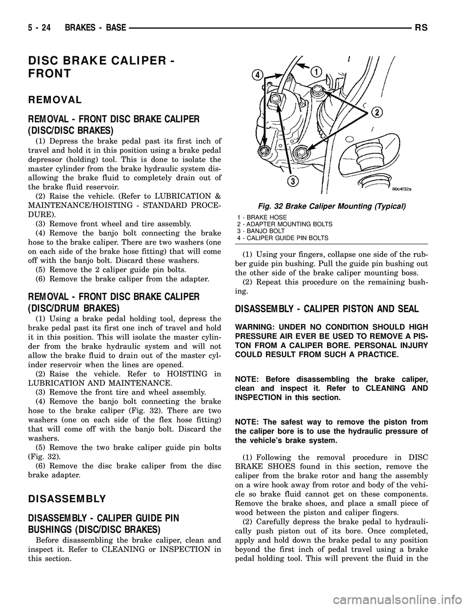
(4) Remove the banjo bolt connecting the brake
hose to the brake caliper (Fig. 32). There are two
washers (one on each side of the flex hose fitting)
that will come off with the banjo bolt. Discard the
washers.
(5) Remove the two brake caliper guide pin bolts
(Fig. 32).
(6) Remove the disc brake caliper from the disc
brake adapter.
DISASSEMBLY
DISASSEMBLY - CALIPER GUIDE PIN
BUSHINGS (DISC/DISC BRAKES)
Before disassembling the brake caliper, clean and
inspect it. Refer to CLEANING or INSPECTION in
this section.(1) Using your fingers, collapse one side of the rub-
ber guide pin bushing. Pull the guide pin bushing out
the other side of the brake caliper mounting boss.
(2) Repeat this procedure on the remaining bush-
ing.
DISASSEMBLY - CALIPER PISTON AND SEAL
WARNING: UNDER NO CONDITION SHOULD HIGH
PRESSURE AIR EVER BE USED TO REMOVE A PIS-
TON FROM A CALIPER BORE. PERSONAL INJURY
COULD RESULT FROM SUCH A PRACTICE.
NOTE: Before disassembling the brake caliper,
clean and inspect it. Refer to CLEANING AND
INSPECTION in this section.
NOTE: The safest way to remove the piston from
the caliper bore is to use the hydraulic pressure of
the vehicle's brake system.
(1) Following the removal procedure in DISC
BRAKE SHOES found in this section, remove the
caliper from the brake rotor and hang the assembly
on a wire hook away from rotor and body of the vehi-
cle so brake fluid cannot get on these components.
Remove the brake shoes, and place a small piece of
wood between the piston and caliper fingers.
(2) Carefully depress the brake pedal to hydrauli-
cally push piston out of its bore. Once completed,
apply and hold down the brake pedal to any position
beyond the first inch of pedal travel using a brake
pedal holding tool. This will prevent the fluid in the
Fig. 32 Brake Caliper Mounting (Typical)
1 - BRAKE HOSE
2 - ADAPTER MOUNTING BOLTS
3 - BANJO BOLT
4 - CALIPER GUIDE PIN BOLTS
5 - 24 BRAKES - BASERS
Page 175 of 2585

(1) Depress the brake pedal past its first inch of
travel and hold it in this position using a brake pedal
depressor (holding) tool. This is done to isolate the
master cylinder from the brake hydraulic system dis-
allowing the brake fluid to completely drain out of
the brake fluid reservoir.
(2) Raise the vehicle. (Refer to LUBRICATION &
MAINTENANCE/HOISTING - STANDARD PROCE-
DURE)
(3) Remove rear wheel and tire assembly from
vehicle.
(4) Remove the banjo bolt connecting the brake
hose to the brake caliper. There are two washers (one
on each side of the brake hose fitting) that will come
off with the banjo bolt. Discard these washers.
(5) Remove the disc brake caliper to adapter guide
pin bolts (Fig. 37).
(6) Remove rear caliper from adapter using the fol-
lowing procedure. First rotate front of caliper up
from the adapter. Then pull the rear of the caliper
and the outboard brake shoe anti-rattle clip out from
under the rear abutment on the adapter (Fig. 38).
(7) If the brake rotor requires removal, it can now
be removed by first removing the retainer clips from
the wheel mounting studs, then pulling the rotor
straight off the studs.
DISASSEMBLY - CALIPER PISTON AND SEAL
WARNING: UNDER NO CONDITION SHOULD HIGH
PRESSURE AIR EVER BE USED TO REMOVE A PIS-
TON FROM A CALIPER BORE. PERSONAL INJURY
COULD RESULT FROM SUCH A PRACTICE.NOTE: Before disassembling the brake caliper,
clean and inspect it. Refer to CLEANING AND
INSPECTION in this section.
NOTE: The safest way to remove the piston from
the caliper bore is to use the hydraulic pressure of
the vehicle's brake system.
(1) Following the removal procedure in DISC
BRAKE SHOES found in this section, remove the
caliper from the brake rotor and hang the assembly
on a wire hook away from rotor and body of the vehi-
cle so brake fluid cannot get on these components.
Remove the brake shoes, and place a small piece of
wood between the piston and caliper fingers.
(2) Carefully depress the brake pedal to hydrauli-
cally push piston out of its bore. Once completed,
apply and hold down the brake pedal to any position
beyond the first inch of pedal travel using a brake
pedal holding tool. This will prevent the fluid in the
master cylinder reservoir from completely draining
out.
(3) Disconnect the brake fluid flex hose from the
caliper assembly and remove it from the vehicle.
CAUTION: Do not use excessive force when clamp-
ing caliper in vise. Excessive vise pressure will
cause bore distortion.
(4) Mount the caliper in a vise equipped with pro-
tective jaws.
(5) Remove the piston dust boot from the caliper
and discard.
Fig. 37 Caliper Guide Pin Bolts
1 - DISC BRAKE CALIPER
2 - ADAPTER
3 - AXLE
4 - GUIDE PIN BOLTS
5 - DRIVESHAFT (AWD MODELS ONLY)
Fig. 38 Removing/Installing Caliper
1 - LIFT THIS END OF CALIPER AWAY FROM ADAPTER FIRST
2 - DISC BRAKE CALIPER
3 - ADAPTER ABUTMENT
4 - OUTBOARD BRAKE SHOE HOLD DOWN CLIP
5 - OUTBOARD BRAKE SHOE
6 - ROTOR
7 - ADAPTER
5 - 28 BRAKES - BASERS
DISC BRAKE CALIPER - REAR (Continued)
Page 182 of 2585

CAUTION: When replacing a master cylinder, be
sure to use the correct master cylinder for the type
of brake system the vehicle is equipped with.
The body of the master cylinder is an anodized alu-
minum casting. It has a machined bore to accept the
master cylinder pistons and threaded ports with
seats for the hydraulic brake line connections.
The brake fluid reservoir is mounted on the top of
the master cylinder. It is made of a see-through
polypropylene type plastic for easy fluid level view-
ing. A brake fluid level switch is attached to the
brake fluid reservoir.
The master cylinder is not a repairable component
and must be replaced if diagnosed to be functioning
improperly. The brake fluid reservoir and brake fluid
level switch can be replaced separately.
CAUTION: Do not hone the bore of the cylinder as
this will remove the anodized surface from the bore.
DESCRIPTION - RHD
The master cylinder used on right hand drive
(RHD) vehicles functions similarly to that used on
left hand drive (LHD) vehicles. The RHD master cyl-
inder, as well as the RHD power brake booster, is
located in the same area, but lower in the engine
compartment than LHD models (Fig. 47). For that
reason an extension manifold is placed between the
fluid reservoir and master cylinder housing allowing
the fluid reservoir to be positioned in the same loca-
tion as on LHD models.
OPERATION
When the brake pedal is depressed, the master cyl-
inder primary and secondary pistons apply brake
pressure through the chassis tubes to the brakes at
each tire and wheel assembly.
The master cylinder primary outlet port supplies
hydraulic pressure to the right front and left rear
brakes. The secondary outlet port supplies hydraulic
pressure to the left front and right rear brakes.
STANDARD PROCEDURE - MASTER CYLINDER
BLEEDING
CAUTION: When clamping master cylinder in vise,
only clamp master cylinder by its mounting flange.
Do not clamp master cylinder piston rod, reservoir,
seal or body.
(1) Clamp master cylinder in a vise.
NOTE: Use correct bleeder tubes when bleeding
master cylinder. Master cylinder outlet ports vary in
size and type depending on whether master cylin-
der is for a vehicle equipped with traction control or
not. Traction control equipped master cylinders
require the additional use of ISO style flare adapt-
ers supplied in Special Tool Package 8822 to be
used in conjunction with Bleeder Tubes, Special
Tool Package 8358.
(2) Attach special tools for bleeding master cylin-
der in the following fashion:
(a)For non-traction control equipped mas-
ter cylinders, thread a Bleeder Tube, Special Tool
8358±1, into each outlet port. Tighten each tube to
17 N´m (145 in. lbs.) torque. Flex bleeder tubes and
place open ends into mouth of fluid reservoir as far
down as possible (Fig. 48).
(b)For traction control equipped master
cylinders, thread one Adapter, Special Tool
8822±2, in each outlet port. Tighten Adapters to 17
N´m (145 in. lbs.) torque. Next, thread a Bleeder
Tube, Special Tool 8358±1, into each Adapter.
Tighten each tube to 17 N´m (145 in. lbs.) torque.
Flex bleeder tubes and place open ends into mouth
of fluid reservoir as far down as possible (Fig. 48).
NOTE: Make sure open ends of bleeder tubes stay
below surface of brake fluid once reservoir is filled
to proper level.
(3) Fill brake fluid reservoir with Mopartbrake
fluid or equivalent conforming to DOT 3 (DOT 4 and
DOT 4+ are acceptable) specifications. Make sure
fluid level is above tips of bleeder tubes in reservoir
to ensure no air is ingested during bleeding.
Fig. 47 RHD MASTER CYLINDER AND POWER
BRAKE BOOSTER
1 - POWER BRAKE BOOSTER
2 - BRAKE FLUID LEVEL SWITCH
3 - FLUID RESERVOIR
4 - MASTER CYLINDER
RSBRAKES - BASE5-35
MASTER CYLINDER (Continued)
Page 196 of 2585
Here is how the height sensing proportioning valve
differs from a standard proportioning valve. As the
height of the rear suspension changes, the height
sensing portion of the proportioning valve changes
the split point of the proportioning valve. When the
height of the rear suspension is low, the proportion-
ing valve interprets this as extra load and the split
point of the proportioning valve is raised to a higher
pressure to allow for more rear braking. When the
height of the rear suspension is high, the proportion-
ing valve interprets this as a light load and the split
point of the proportioning valve is lowered to a lower
pressure and rear braking is reduced.
The height sensing proportioning valve regulates
the pressure by sensing the load condition of the
vehicle through the movement of the proportioning
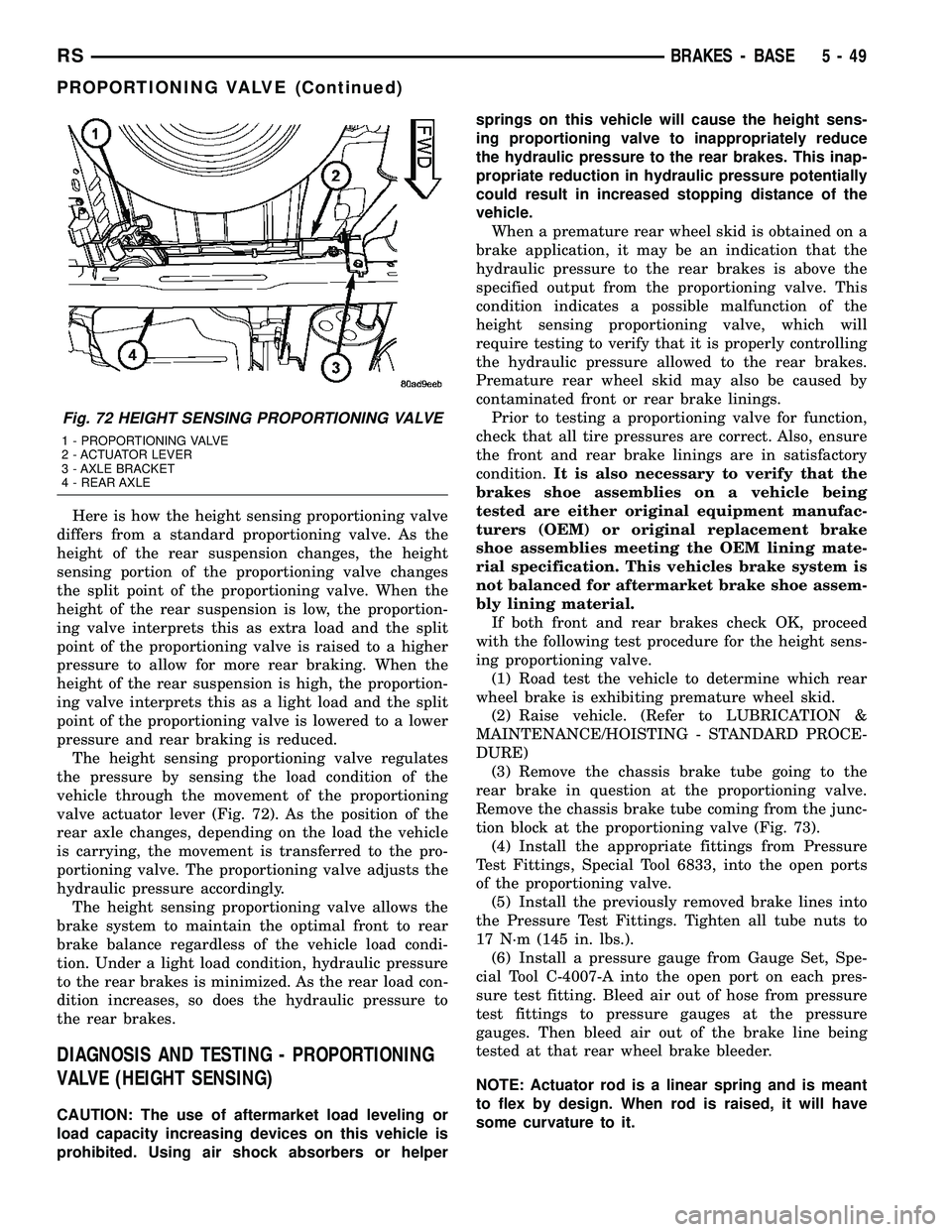
valve actuator lever (Fig. 72). As the position of the
rear axle changes, depending on the load the vehicle
is carrying, the movement is transferred to the pro-
portioning valve. The proportioning valve adjusts the
hydraulic pressure accordingly.
The height sensing proportioning valve allows the
brake system to maintain the optimal front to rear
brake balance regardless of the vehicle load condi-
tion. Under a light load condition, hydraulic pressure
to the rear brakes is minimized. As the rear load con-
dition increases, so does the hydraulic pressure to
the rear brakes.
DIAGNOSIS AND TESTING - PROPORTIONING
VALVE (HEIGHT SENSING)
CAUTION: The use of aftermarket load leveling or
load capacity increasing devices on this vehicle is
prohibited. Using air shock absorbers or helpersprings on this vehicle will cause the height sens-
ing proportioning valve to inappropriately reduce
the hydraulic pressure to the rear brakes. This inap-
propriate reduction in hydraulic pressure potentially
could result in increased stopping distance of the
vehicle.
When a premature rear wheel skid is obtained on a
brake application, it may be an indication that the
hydraulic pressure to the rear brakes is above the
specified output from the proportioning valve. This
condition indicates a possible malfunction of the
height sensing proportioning valve, which will
require testing to verify that it is properly controlling
the hydraulic pressure allowed to the rear brakes.
Premature rear wheel skid may also be caused by
contaminated front or rear brake linings.
Prior to testing a proportioning valve for function,
check that all tire pressures are correct. Also, ensure
the front and rear brake linings are in satisfactory
condition.It is also necessary to verify that the
brakes shoe assemblies on a vehicle being
tested are either original equipment manufac-
turers (OEM) or original replacement brake
shoe assemblies meeting the OEM lining mate-
rial specification. This vehicles brake system is
not balanced for aftermarket brake shoe assem-
bly lining material.
If both front and rear brakes check OK, proceed
with the following test procedure for the height sens-
ing proportioning valve.
(1) Road test the vehicle to determine which rear
wheel brake is exhibiting premature wheel skid.
(2) Raise vehicle. (Refer to LUBRICATION &
MAINTENANCE/HOISTING - STANDARD PROCE-
DURE)
(3) Remove the chassis brake tube going to the
rear brake in question at the proportioning valve.
Remove the chassis brake tube coming from the junc-
tion block at the proportioning valve (Fig. 73).
(4) Install the appropriate fittings from Pressure
Test Fittings, Special Tool 6833, into the open ports
of the proportioning valve.
(5) Install the previously removed brake lines into
the Pressure Test Fittings. Tighten all tube nuts to
17 N´m (145 in. lbs.).
(6) Install a pressure gauge from Gauge Set, Spe-
cial Tool C-4007-A into the open port on each pres-
sure test fitting. Bleed air out of hose from pressure
test fittings to pressure gauges at the pressure
gauges. Then bleed air out of the brake line being
tested at that rear wheel brake bleeder.
NOTE: Actuator rod is a linear spring and is meant
to flex by design. When rod is raised, it will have
some curvature to it.
Fig. 72 HEIGHT SENSING PROPORTIONING VALVE
1 - PROPORTIONING VALVE
2 - ACTUATOR LEVER
3 - AXLE BRACKET
4 - REAR AXLE
RSBRAKES - BASE5-49
PROPORTIONING VALVE (Continued)
Page 223 of 2585

tioning valve. The EVBP system uses the ABS sys-
tem to control the slip of the rear wheels in partial
braking range. The braking force of the rear wheels
is controlled electronically by using the inlet and out-
let valves located in the integrated control unit
(ICU).
EVBP activation is invisible to the customer since
there is no pump motor noise or brake pedal feed-
back.
DESCRIPTION - TRACTION CONTROL SYSTEM
Traction control reduces wheel slip and maintains
traction at the driving wheels at speeds below 56
km/h (35 mph) when road surfaces are slippery. The
traction control system reduces wheel slip by braking
the wheel that is losing traction.
HYDRAULIC SHUTTLE VALVES
Two pressure relief hydraulic shuttle valves are
included on vehicles with traction control. These
valves are located inside the HCU and cannot be ser-
viced separately from the HCU.
TRACTION CONTROL LAMP
The traction control function lamp is located in the
transmission range indicator display of the instru-
ment cluster, displaying TRAC, TRAC OFF or nei-
ther depending on system mode.
The TRAC OFF lamp is controlled by a Traction
Control Off switch that is a momentary contact type
switch. The Traction Control Off switch is located on
the steering column upper shroud.
OPERATION
OPERATION - ANTILOCK BRAKE SYSTEM
There are a few performance characteristics of the
Mark 20e Antilock Brake System that may at first
seem abnormal, but in fact are normal. These char-
acteristics are described below.
NORMAL BRAKING
Under normal braking conditions, the ABS func-
tions the same as a standard base brake system with
a diagonally split master cylinder and conventional
vacuum assist.
ABS BRAKING
ABS operation is available at all vehicle speeds
above 3±5 mph. If a wheel locking tendency is
detected during a brake application, the brake system
enters the ABS mode. During ABS braking, hydraulic
pressure in the four wheel circuits is modulated to
prevent any wheel from locking. Each wheel circuit is
designed with a set of electric solenoids to allow mod-ulation, although for vehicle stability, both rear wheel
solenoids receive the same electrical signal. Wheel
lockup may be perceived at the very end of an ABS
stop and is considered normal.
During an ABS stop, the brakes hydraulic system
is still diagonally split. However, the brake system
pressure is further split into three control channels.
During antilock operation of the vehicle's brake sys-
tem, the front wheels are controlled independently
and are on two separate control channels, and the
rear wheels of the vehicle are controlled together.
The system can build and release pressure at each
wheel, depending on signals generated by the wheel
speed sensors (WSS) at each wheel and received at
the controller antilock brake (CAB).
NOISE AND BRAKE PEDAL FEEL
During ABS braking, some brake pedal movement
may be felt. In addition, ABS braking will create
ticking, popping, or groaning noises heard by the
driver. This is normal and is due to pressurized fluid
being transferred between the master cylinder and
the brakes. If ABS operation occurs during hard
braking, some pulsation may be felt in the vehicle
body due to fore and aft movement of the suspension
as brake pressures are modulated.
At the end of an ABS stop, ABS is turned off when
the vehicle is slowed to a speed of 3±4 mph. There
may be a slight brake pedal drop anytime that the
ABS is deactivated, such as at the end of the stop
when the vehicle speed is less than 3 mph or during
an ABS stop where ABS is no longer required. These
conditions exist when a vehicle is being stopped on a
road surface with patches of ice, loose gravel, or sand
on it. Also, stopping a vehicle on a bumpy road sur-
face activates ABS because of the wheel hop caused
by the bumps.
TIRE NOISE AND MARKS
Although the ABS system prevents complete wheel
lockup, some wheel slip is desired in order to achieve
optimum braking performance. Wheel slip is defined
as follows: 0 percent slip means the wheel is rolling
freely and 100 percent slip means the wheel is fully
locked. During brake pressure modulation, wheel slip
is allowed to reach up to 25±30 percent. This means
that the wheel rolling velocity is 25±30 percent less
than that of a free rolling wheel at a given vehicle
speed. This slip may result in some tire chirping,
depending on the road surface. This sound should not
be interpreted as total wheel lockup.
Complete wheel lockup normally leaves black tire
marks on dry pavement. The ABS will not leave dark
black tire marks since the wheel never reaches a
fully locked condition. However, tire marks may be
noticeable as light patched marks.
5 - 76 BRAKES - ABSRS
BRAKES - ABS (Continued)
Page 226 of 2585

BLEEDING
When bleeding the ABS system, the following
bleeding sequence must be followed to insure com-
plete and adequate bleeding.
(1) Make sure all hydraulic fluid lines are installed
and properly torqued.
(2) Connect the DRBIIItscan tool to the diagnos-
tics connector. The diagnostic connector is located
under the lower steering column cover to the left of
the steering column.
(3) Using the DRB, check to make sure the CAB
does not have any fault codes stored. If it does, clear
them using the DRB.
WARNING:
WHEN BLEEDING THE BRAKE SYSTEM
WEAR SAFETY GLASSES. A CLEAR BLEED TUBE
MUST BE ATTACHED TO THE BLEEDER SCREWS
AND SUBMERGED IN A CLEAR CONTAINER FILLED
PART WAY WITH CLEAN BRAKE FLUID. DIRECT THE
FLOW OF BRAKE FLUID AWAY FROM YOURSELF
AND THE PAINTED SURFACES OF THE VEHICLE.
BRAKE FLUID AT HIGH PRESSURE MAY COME OUT
OF THE BLEEDER SCREWS WHEN OPENED.
(4) Bleed the base brake system using the stan-
dard pressure or manual bleeding procedure. (Refer
to 5 - BRAKES - BASE - STANDARD PROCEDURE)
(5) Using the DRB, select ANTILOCK BRAKES,
followed by MISCELLANEOUS, then BLEED
BRAKES. Follow the instructions displayed. When
the scan tool displays TEST COMPLETED, discon-
nect the scan tool and proceed.
(6) Bleed the base brake system a second time.
Check brake fluid level in the reservoir periodically
to prevent emptying, causing air to enter the hydrau-
lic system.
(7) Fill the master cylinder reservoir to the full
level.
(8) Test drive the vehicle to be sure the brakes are
operating correctly and that the brake pedal does not
feel spongy.
SPECIFICATIONS
ABS FASTENER TORQUE
(Refer to 5 - BRAKES - BASE - SPECIFICA-
TIONS)
TONE WHEEL RUNOUT
DESCRIPTION SPECIFICATION
Front Tone Wheel
Maximum Runout0.15 mm (0.006 in.)
Rear Tone Wheel
Maximum Runout0.15 mm (0.006 in.)
WHEEL SPEED SENSOR AIR GAP
DESCRIPTION SPECIFICATION
Front Sensor0.35 ± 1.20 mm
0.014 ± 0.047 in.
Rear Sensor0.40 ± 1.20 mm
0.016 ± 0.047 in.
FRONT WHEEL SPEED
SENSOR
REMOVAL
(1) Raise vehicle. (Refer to LUBRICATION &
MAINTENANCE/HOISTING - STANDARD PROCE-
DURE)
(2) Remove the tire and wheel assembly.
(3) Remove the sensor cable routing clamp screws.
CAUTION: When disconnecting the wheel speed
sensor from vehicle wiring harness, be careful not
to damage pins on connector
(4) Remove speed sensor cable grommets from
intermediate bracket on strut.
(5) Disconnect speed sensor cable from vehicle wir-
ing harness behind fender well shield.
(6) Remove the wheel speed sensor head mounting
bolt (Fig. 1).
(7) Remove sensor head from steering knuckle. If
sensor has seized due to corrosion,DO NOT USE
PLIERS ON SENSOR HEAD.Use a hammer and a
Fig. 1 Front Wheel Speed Sensor Attaching Bolt
1 - MOUNTING BOLT
2 - WHEEL SPEED SENSOR
3 - DRIVESHAFT
4 - TONE WHEEL
5 - STEERING KNUCKLE
RSBRAKES - ABS5-79
BRAKES - ABS (Continued)
Page 231 of 2585

ABS PRIMARY HYDRAULIC CIRCUIT AND
SOLENOID VALVE FUNCTION (ABS WITHOUT
TRACTION CONTROL)
The hydraulic diagram (Fig. 7) shows the vehicle in
the ABS braking mode. The diagram shows one
wheel is slipping because the driver is attempting to
stop the vehicle at a faster rate than is allowed by
the surface on which the tires are riding.²The normally open and normally closed valves
modulate (build/decay) the brake hydraulic pressure
as required.
²The pump/motor is switched on so that the
brake fluid from the low pressure accumulators is
returned to the master cylinder circuits.
²The brake fluid is routed to either the master
cylinder or the wheel brake depending on the posi-
tion of the normally open valve.
Fig. 7 ABS Without Traction Control - Primary Hydraulic Circuit
1 - OUTLET VALVE
2 - PUMP PISTON
3 - PUMP MOTOR (ON)
4 - LOW PRESSURE ACCUMULATOR PRESSURE
5 - LOW PRESSURE ACCUMULATOR
6 - NORMALLY CLOSED VALVE (MODULATING)
7 - TO RIGHT FRONT WHEEL8 - NORMALLY OPEN VALVE (MODULATING)
9 - FROM MASTER CYLINDER
10 - MASTER CYLINDER PRESSURE
11 - CONTROLLED WHEEL PRESSURE
12 - PUMP INTERSTAGE PRESSURE
13 - NOISE DAMPER CHAMBER
5 - 84 BRAKES - ABSRS
HYDRAULIC/MECHANICAL (Continued)
Page 232 of 2585

ABS SECONDARY HYDRAULIC CIRCUIT AND
SOLENOID VALVE FUNCTION (ABS WITHOUT
TRACTION CONTROL)
The hydraulic diagram (Fig. 8) shows the vehicle in
the ABS braking mode. The diagram shows one
wheel is slipping because the driver is attempting to
stop the vehicle at a faster rate than is allowed by
the surface on which the tires are riding.
²The normally open and normally closed valves
modulate (build/decay) the brake hydraulic pressure
as required.²The pump/motor is switched on so that the
brake fluid from the low pressure accumulators is
returned to the master cylinder circuits.
²The brake fluid will then be routed to either the
master cylinder or the wheel brake depending on the
position of the normally open valve.
²In the secondary circuit, 1.2 cc brake fluid is
taken in by the lip seal saver to protect the lip seals
on the master cylinder piston.
Fig. 8 ABS Without Traction Control - Secondary Hydraulic Circuit
1 - OUTLET VALVE
2 - PUMP PISTON
3 - LOW PRESSURE ACCUMULATOR PRESSURE
4 - TO RIGHT FRONT WHEEL
5 - FROM MASTER CYLINDER6 - MASTER CYLINDER PRESSURE
7 - CONTROLLED WHEEL PRESSURE
8 - PUMP INTERSTAGE PRESSURE
9 - LIP SEAL SAVER (SECONDARY CIRCUIT ONLY)
RSBRAKES - ABS5-85
HYDRAULIC/MECHANICAL (Continued)
Page 234 of 2585

ABS BRAKING HYDRAULIC CIRCUIT, SOLENOID
VALVE, AND SHUTTLE VALVE FUNCTION (ABS
WITH TRACTION CONTROL)
The hydraulic diagram (Fig. 10) shows the vehicle
in the ABS braking mode. The diagram shows one
wheel is slipping because the driver is attempting to
stop the vehicle at a faster rate than is allowed by
the surface on which the tires are riding.
²The hydraulic shuttle valve closes upon brake
application so that the pump/motor cannot siphon
brake fluid from the master cylinder.²The normally open and normally closed valves
modulate (build/decay) the brake hydraulic pressure
as required.
²The pump/motor is switched on so that the
brake fluid from the low pressure accumulators is
returned to the master cylinder circuits.
²The brake fluid is routed to either the master
cylinder or the wheel brake depending on the posi-
tion of the normally open valve.
Fig. 10 ABS With Traction Control - ABS Braking Hydraulic Circuit
1 - OUTLET VALVE
2 - PUMP PISTON
3 - PUMP MOTOR (ON)
4 - SUCTION VALVE
5 - LOW PRESSURE ACCUMULATOR
6 - NORMALLY CLOSED VALVE (MODULATING)
7 - TO RIGHT FRONT WHEEL
8 - NORMALLY OPEN VALVE (MODULATING)9 - NORMALLY OPEN ASR VALVE (OFF)
10 - FROM MASTER CYLINDER
11 - HYDRAULIC SHUTTLE VALVE
12 - MASTER CYLINDER PRESSURE
13 - CONTROLLED WHEEL PRESSURE
14 - LOW PRESSURE ACCUMULATOR PRESSURE
15 - PUMP INTERSTAGE PRESSURE
16 - NOISE DAMPER CHAMBER
RSBRAKES - ABS5-87
HYDRAULIC/MECHANICAL (Continued)
Page 246 of 2585

INSTALLATION - PARKING BRAKE CABLE(INTERMEDIATE) ......................66
INSTALLATION - PARKING BRAKE CABLE (RIGHT REAR) ........................66
INSTALLATION - PARKING BRAKE CABLE (LEFT REAR) .........................66
ADJUSTMENTS ADJUSTMENT - PARKING BRAKE CABLES . 66
CABLES - PARKING BRAKE (EXPORT) REMOVAL - FRONT CABLE ...............67
INSTALLATION - FRONT CABLE ............67
LEVER - PARKING BRAKE REMOVAL .............................67 INSTALLATION
.........................67
LEVER - PARKING BRAKE (EXPORT) REMOVAL - PARKING BRAKE LEVER ANDFRONT CABLE .......................68
INSTALLATION - PARKING BRAKE LEVER AND FRONT CABLE ...................69
SHOES - PARKING BRAKE REMOVAL .............................69
INSTALLATION .........................75
ADJUSTMENTS ADJUSTMENT - PARKING BRAKE SHOES . . 76
BRAKES - BASE
DESCRIPTION
DESCRIPTION - BASE BRAKES
The base brake system consists of the following
components: ² Brake pedal
² Power brake booster
² Master cylinder
² Brake tubes and hoses
² Proportioning valve (non-ABS vehicles only)
² Disc brakes
² Drum brakes
² Brake lamp switch
² Brake fluid level switch
² Parking brakes
Front disc brakes control the braking of the front
wheels; rear braking is controlled by rear drum
brakes or rear disc brakes depending on options. The hydraulic brake system is diagonally split on
both the non-antilock braking systems and antilock
braking systems. That means the left front and right
rear brakes are on one hydraulic circuit and the right
front and left rear are on the other. For information on the brake lamp switch, (Refer
to 8 - ELECTRICAL/LAMPS/LIGHTING - EXTERI-
OR/BRAKE LAMP SWITCH - DESCRIPTION) Vehicles equipped with the optional antilock brake
system (ABS) use a system designated Mark 20e. It
is available with or without traction control. This
system shares most base brake hardware used on
vehicles without ABS. ABS components are described
in detail in ANTILOCK BRAKE SYSTEM.
DESCRIPTION - BASE BRAKES (EXPORT)
Four-Wheel Disc Antilock Brakes are standard on
all models.
OPERATION - BASE BRAKES
When a vehicle needs to be stopped, the driver
applies the brake pedal. The brake pedal pushes the
input rod of the power brake booster into the booster.
The booster uses vacuum to ease pedal effort as force
is transferred through the booster to the master cyl-
inder. The booster's output rod pushes in the master
cylinder's primary and secondary pistons applying
hydraulic pressure through the chassis brake tubes
to the brakes at each tire and wheel assembly. The parking brakes are foot-operated. When
applied, the parking brake lever pulls on cables that
actuate brake shoes at each rear wheel. These shoes
come in contact with a hub mounted drum (drum for
disc/drum brakes or drum-in-hat for disc/disc brakes)
and hold it in place.
WARNING
WARNING: DUST AND DIRT ACCUMULATING ON
BRAKE PARTS DURING NORMAL USE MAY CON-
TAIN ASBESTOS FIBERS FROM PRODUCTION OR
AFTERMARKET BRAKE LININGS. BREATHING
EXCESSIVE CONCENTRATIONS OF ASBESTOS
FIBERS CAN CAUSE SERIOUS BODILY HARM.
EXERCISE CARE WHEN SERVICING BRAKE
PARTS. DO NOT SAND OR GRIND BRAKE LINING
UNLESS EQUIPMENT USED IS DESIGNED TO CON-
TAIN THE DUST RESIDUE. DO NOT CLEAN BRAKE
PARTS WITH COMPRESSED AIR OR BY DRY
BRUSHING. CLEANING SHOULD BE DONE BY
DAMPENING THE BRAKE COMPONENTS WITH A
FINE MIST OF WATER, THEN WIPING THE BRAKE
COMPONENTS CLEAN WITH A DAMPENED CLOTH.
DISPOSE OF CLOTH AND ALL RESIDUE CONTAIN-
ING ASBESTOS FIBERS IN AN IMPERMEABLE
CONTAINER WITH THE APPROPRIATE LABEL. FOL-
LOW PRACTICES PRESCRIBED BY THE OCCUPA-
TIONAL SAFETY AND HEALTH ADMINISTRATION
(OSHA) AND THE ENVIRONMENTAL PROTECTION
AGENCY (EPA) FOR THE HANDLING, PROCESSING,
AND DISPOSING OF DUST OR DEBRIS THAT MAY
CONTAIN ASBESTOS FIBERS.
RS BRAKES5s-3