service interval CHRYSLER VOYAGER 2004 Service Manual
[x] Cancel search | Manufacturer: CHRYSLER, Model Year: 2004, Model line: VOYAGER, Model: CHRYSLER VOYAGER 2004Pages: 2585, PDF Size: 62.54 MB
Page 15 of 2585
²Society of Automotive Engineers (SAE)
²American Petroleum Institute (API)
²National Lubricating Grease Institute (NLGI)
API SERVICE GRADE CERTIFIED
Use an engine oil that is API Certified (GF-3).
Mopartprovides engine oils, meeting Material Stan-
dard MS-6395, that meet or exceed this requirement.
SAE VISCOSITY
An SAE viscosity grade is used to specify the vis-
cosity of engine oil. Use only engine oils with multi-
ple viscosities such as 5W-30 or 10W-30. These are
specified with a dual SAE viscosity grade which indi-
cates the cold-to-hot temperature viscosity range.
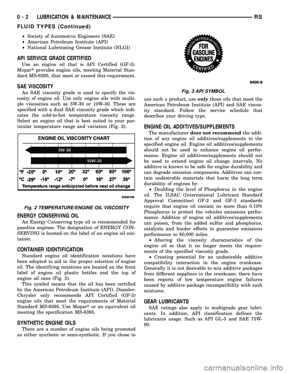
Select an engine oil that is best suited to your par-
ticular temperature range and variation (Fig. 2).
ENERGY CONSERVING OIL
An Energy Conserving type oil is recommended for
gasoline engines. The designation of ENERGY CON-
SERVING is located on the label of an engine oil con-
tainer.
CONTAINER IDENTIFICATION
Standard engine oil identification notations have
been adopted to aid in the proper selection of engine
oil. The identifying notations are located on the front
label of engine oil plastic bottles and the top of
engine oil cans (Fig. 3).
This symbol means that the oil has been certified
by the American Petroleum Institute (API). Diamler-
Chrysler only recommends API Certified (GF-3)
engine oils that meet the requirements of Material
Standard MS-6395. Use Mopartor an equivalent oil
meeting the specification MS-6395.
SYNTHETIC ENGINE OILS
There are a number of engine oils being promoted
as either synthetic or semi-synthetic. If you chose touse such a product, useonlythose oils that meet the
American Petroleum Institute (API) and SAE viscos-
ity standard. Follow the service schedule that
describes your driving type.
ENGINE OIL ADDITIVES/SUPPLEMENTS
The manufacturerdoes not recommendthe addi-
tion of any engine oil additives/supplements to the
specified engine oil. Engine oil additives/supplements
should not be used to enhance engine oil perfor-
mance. Engine oil additives/supplements should not
be used to extend engine oil change intervals. No
additive is known to be safe for engine durability and
can degrade emission components. Additives can con-
tain undesirable materials that harm the long term
durability of engines by:
²Doubling the level of Phosphorus in the engine
oil. The ILSAC (International Lubricant Standard
Approval Committee) GF-2 and GF-3 standards
require that engine oil contain no more than 0.10%
Phosphorus to protect the vehicles emissions perfor-
mance. Addition of engine oil additives/supplements
can poison, from the added sulfur and phosphorus,
catalysts and hinder efforts to guarantee emissions
performance to 80,000 miles.
²Altering the viscosity characteristics of the
engine oil so that it no longer meets the require-
ments of the specified viscosity grade.
²Creating potential for an undesirable additive
compatibility interaction in the engine crankcase.
Generally it is not desirable to mix additive packages
from different suppliers in the crankcase; there have
been reports of low temperature engine failures
caused by additive package incompatibility with such
mixtures.
GEAR LUBRICANTS
SAE ratings also apply to multigrade gear lubri-
cants. In addition, API classification defines the
lubricants usage. Such as API GL-5 and SAE 75W-
90.
Fig. 2 TEMPERATURE/ENGINE OIL VISCOSITY
Fig. 3 API SYMBOL
0 - 2 LUBRICATION & MAINTENANCERS
FLUID TYPES (Continued)
Page 17 of 2585
FUEL REQUIREMENTS
The vehicle will operate on both unleaded gasoline
with an octane rating of 87, or E-85 fuel, or any mix-
ture of these two.
For best results, a refueling pattern that alternates
between E-85 and unleaded gasoline should be
avoided. When you do switch fuels, it is recom-
mended that
²you do not switch when the fuel gauge indicates
less than 1/4 full
²you do not add less than 5 gallons when refuel-
ing
²you operate the vehicle immediately after refuel-
ing for a period of at least 5 minutes
Observing these precautions will avoid possible
hard starting and/or significant deterioration in
driveability during warm up.
FFV STARTING
The characteristics of E-85 fuel make it unsuitable
for use when ambient temperatures fall below 0ÉF. In
the range of 0ÉF to 32ÉF, you may experience an
increase in the time it takes for your engine to start,
and a deterioration in driveability (sags and/or hesi-
tations) until the engine is fully warmed up.
Engine Operating on E-85 Fuel
If vehicle operates on E-85 fuel either full or part-
time, use only MopartFlexible Fuel 5W-30 engine oil
or an equivalent that meets DaimlerChrysler Stan-
dard MS-9214. Equivalent commercial Flexible Fuel
engine oils may be labeled as Multi-Fuel, Variable
Fuel, Flexible Fuel, etc. These engine oils may be
satisfactory if they meet the DaimlerChrysler Stan-
dard.
SAE 5W-30 engine oil is preferred for use in Flex-
ible Fuel engines.
CAUTION: If Flexible Fuel engine oil is not used
when using E-85 fuel, engine wear or damage may
result.
CRUISING RANGE
Because E-85 fuel contains less energy per gallon
than gasoline, you will experience an increase in fuel
consumption. You can expect your MPG and your
driving range to decrease by about 30% compared to
gasoline operation.
DESCRIPTION - AUTOMATIC/MANUAL
TRANSAXLE FLUID
NOTE: Refer to the maintenance schedules for the
recommended maintenance (fluid/filter change)
intervals for these transaxles.NOTE: All transaxles have a common transmission
and differential sump. Filling the transaxle accom-
modates the differential as well.
TRANSMISSION FLUID
MopartATF+4 (Automatic Transmission Fluid) is
required in the 41TE automatic and T850 manual
transaxles. Substitute fluids can induce transmission
problems and/or failure.
MopartATF+4 (Automatic Transmission Fluid)
when new is red in color. The ATF is dyed red so it
can be identified from other fluids used in the vehicle
such as engine oil or antifreeze. The red color is not
permanent and is not an indicator of fluid condition.
As the vehicle is driven, the ATF will begin to look
darker in color and may eventually become brown.
This is normal.ATF+4 also has a unique odor that
may change with age. Consequently,odor and color
cannot be used to indicate the fluid condition
or the need for a fluid change.
FLUID ADDITIVES
DaimlerChrysler strongly recommends against the
addition of any fluids to the transmission, other than
those automatic transmission fluids listed above.
Exceptions to this policy are the use of special dyes
to aid in detecting fluid leaks.
Various ªspecialº additives and supplements exist
that claim to improve shift feel and/or quality. These
additives and others also claim to improve converter
clutch operation and inhibit overheating, oxidation,
varnish, and sludge. These claims have not been sup-
ported to the satisfaction of DaimlerChrysler and
these additivesmust not be used.The use of trans-
mission ªsealersº should also be avoided, since they
may adversely affect the integrity of transmission
seals.
DESCRIPTION - FUEL REQUIREMENTS
Your engine is designed to meet all emissions reg-
ulations and provide excellent fuel economy and per-
formance when using high quality unleaded gasoline
having an octane rating of 87. The use of premium
gasoline is not recommended. The use of premium
gasoline will provide no benefit over high quality reg-
ular gasoline, and in some circumstances may result
in poorer performance.
Light spark knock at low engine speeds is not
harmful to your engine. However, continued heavy
spark knock at high speeds can cause damage and
immediate service is required. Engine damage result-
ing from operation with a heavy spark knock may
not be covered by the new vehicle warranty.
Poor quality gasoline can cause problems such as
hard starting, stalling and hesitations. If you experi-
0 - 4 LUBRICATION & MAINTENANCERS
FLUID TYPES (Continued)
Page 20 of 2585
FLUID FILL/CHECK
LOCATIONS
DESCRIPTION
The fluid check/fill point locations are located in
each applicable service manual section.
LUBRICATION POINTS
DESCRIPTION
Lubrication point locations are located in each
applicable Sections.
MAINTENANCE SCHEDULES
DESCRIPTION
DESCRIPTION
There are two maintenance schedules that show
therequiredservice for your vehicle.
First is ScheduleªBº. It is for vehicles that are
operated under the conditions that are listed below
and at the beginning of the schedule.
²Day or night temperatures are below 32É F (0É
C).
²Stop and go driving.
²Extensive engine idling.
²Driving in dusty conditions.
²Short trips of less than 10 miles (16 km).
²More than 50% of your driving is at sustained
high speeds during hot weather, above 90É F (32É C).
²Trailer towing.L
²Taxi, police, or delivery service (commercial ser-
vice).L
²Off-road or desert operation.
NOTE: Most vehicles are operated under the condi-
tions listed for Schedule(B(.
Second is ScheduleªAº. It is for vehicles that are
not operated under any of the conditions listed under
Schedule9B9.
Use the schedule that best describes your driving
conditions. Where time and mileage are listed, follow
the interval that occurs first.
CAUTION: Failure to perform the required mainte-
nance items may result in damage to the vehicle.
At Each Stop for Fuel
²Check the engine oil level about 5 minutes after
a fully warmed engine is shut off. Checking the oil
level while the vehicle is on level ground will
improve the accuracy of the oil level reading. Add oil
only when the level is at or below the ADD or MIN
mark.
²Check the windshield washer solvent and add if
required.
Once a Month
²Check tire pressure and look for unusual wear
or damage.
²Inspect the battery and clean and tighten the
terminals as required.
²Check the fluid levels of coolant reservoir, brake
master cylinder and transmission; add as needed.
²Check all lights and all other electrical items for
correct operation.
At Each Oil Change
²Change the engine oil filter.
²Inspect the exhaust system.
²Inspect the brake hoses.
²Inspect the CV joints and front suspension com-
ponents.
²Check the automatic transmission fluid level.
²Check the coolant level, hoses, and clamps.
Tire Rotation
²Rotate the tires at 6,000 miles (10 000 km).
SCHEDULE B
Follow schedule ªBº if you usually operate your
vehicle under one or more of the following conditions.
Change the automatic transmission fluid and filter
every 60,000 miles (96 000 km) if the vehicle is usu-
ally operated under one or more of the conditions
marked with anL.
²Day or night temperatures are below 32É F (0É
C).
²Stop and go driving.
²Extensive engine idling.
²Driving in dusty conditions.
²Short trips of less than 10 miles (16 km).
²More than 50% of your driving is at sustained
high speeds during hot weather, above 90É F (32É C).
²Trailer towing.L
²Taxi, police, or delivery service (commercial ser-
vice).L
²Off-road or desert operation.
RSLUBRICATION & MAINTENANCE0-7
Page 25 of 2585
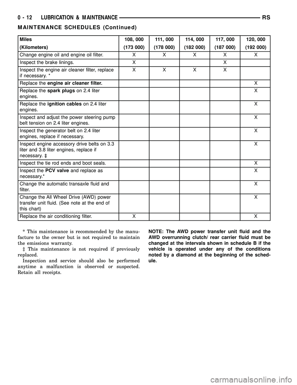
Miles 108, 000 111, 000 114, 000 117, 000 120, 000
(Kilometers) (173 000) (178 000) (182 000) (187 000) (192 000)
Change engine oil and engine oil filter.XXXX X
Inspect the brake linings. X X
Inspect the engine air cleaner filter, replace
if necessary. *XXXX
Replace theengine air cleaner filter.X
Replace thespark plugson 2.4 liter
engines.X
Replace theignition cableson 2.4 liter
engines.X
Inspect and adjust the power steering pump
belt tension on 2.4 liter engines.X
Inspect the generator belt on 2.4 liter
engines, replace if necessary.X
Inspect engine accessory drive belts on 3.3
liter and 3.8 liter engines, replace if
necessary. ³X
Inspect the tie rod ends and boot seals. X
Inspect thePCV valveand replace as
necessary.*X
Change the automatic transaxle fluid and
filter.X
Change the All Wheel Drive (AWD) power
transfer unit fluid. (See note at the end of
this chart)X
Replace the air conditioning filter. X X
* This maintenance is recommended by the manu-
facture to the owner but is not required to maintain
the emissions warranty.
³ This maintenance is not required if previously
replaced.
Inspection and service should also be performed
anytime a malfunction is observed or suspected.
Retain all receipts.NOTE: The AWD power transfer unit fluid and the
AWD overrunning clutch/ rear carrier fluid must be
changed at the intervals shown in schedule B if the
vehicle is operated under any of the conditions
noted by a diamond at the beginning of the sched-
ule.
0 - 12 LUBRICATION & MAINTENANCERS
MAINTENANCE SCHEDULES (Continued)
Page 28 of 2585
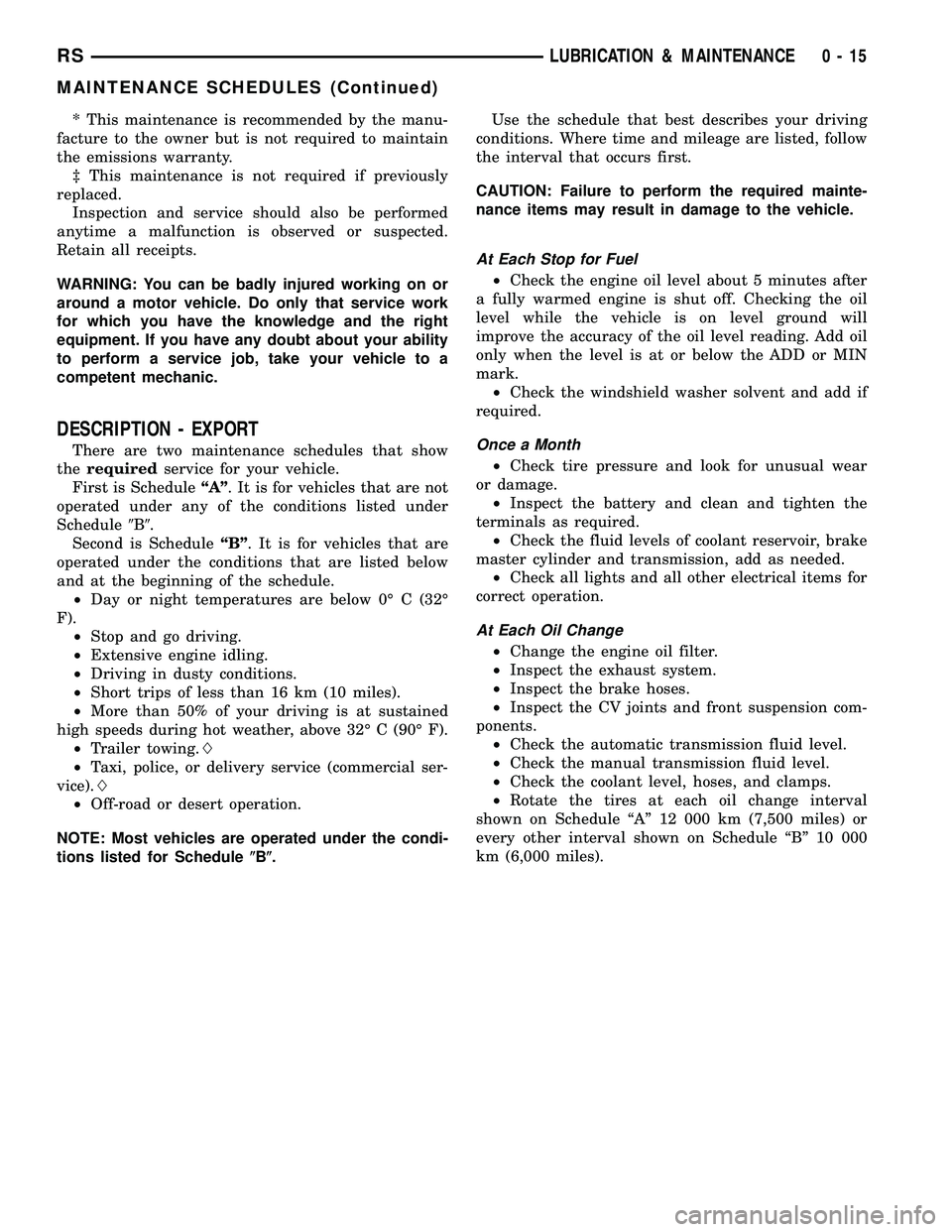
* This maintenance is recommended by the manu-
facture to the owner but is not required to maintain
the emissions warranty.
³ This maintenance is not required if previously
replaced.
Inspection and service should also be performed
anytime a malfunction is observed or suspected.
Retain all receipts.
WARNING: You can be badly injured working on or
around a motor vehicle. Do only that service work
for which you have the knowledge and the right
equipment. If you have any doubt about your ability
to perform a service job, take your vehicle to a
competent mechanic.
DESCRIPTION - EXPORT
There are two maintenance schedules that show
therequiredservice for your vehicle.
First is ScheduleªAº. It is for vehicles that are not
operated under any of the conditions listed under
Schedule9B9.
Second is ScheduleªBº. It is for vehicles that are
operated under the conditions that are listed below
and at the beginning of the schedule.
²Day or night temperatures are below 0É C (32É
F).
²Stop and go driving.
²Extensive engine idling.
²Driving in dusty conditions.
²Short trips of less than 16 km (10 miles).
²More than 50% of your driving is at sustained
high speeds during hot weather, above 32É C (90É F).
²Trailer towing.L
²Taxi, police, or delivery service (commercial ser-
vice).L
²Off-road or desert operation.
NOTE: Most vehicles are operated under the condi-
tions listed for Schedule(B(.Use the schedule that best describes your driving
conditions. Where time and mileage are listed, follow
the interval that occurs first.
CAUTION: Failure to perform the required mainte-
nance items may result in damage to the vehicle.
At Each Stop for Fuel
²Check the engine oil level about 5 minutes after
a fully warmed engine is shut off. Checking the oil
level while the vehicle is on level ground will
improve the accuracy of the oil level reading. Add oil
only when the level is at or below the ADD or MIN
mark.
²Check the windshield washer solvent and add if
required.
Once a Month
²Check tire pressure and look for unusual wear
or damage.
²Inspect the battery and clean and tighten the
terminals as required.
²Check the fluid levels of coolant reservoir, brake
master cylinder and transmission, add as needed.
²Check all lights and all other electrical items for
correct operation.
At Each Oil Change
²Change the engine oil filter.
²Inspect the exhaust system.
²Inspect the brake hoses.
²Inspect the CV joints and front suspension com-
ponents.
²Check the automatic transmission fluid level.
²Check the manual transmission fluid level.
²Check the coolant level, hoses, and clamps.
²Rotate the tires at each oil change interval
shown on Schedule ªAº 12 000 km (7,500 miles) or
every other interval shown on Schedule ªBº 10 000
km (6,000 miles).
RSLUBRICATION & MAINTENANCE0-15
MAINTENANCE SCHEDULES (Continued)
Page 36 of 2585
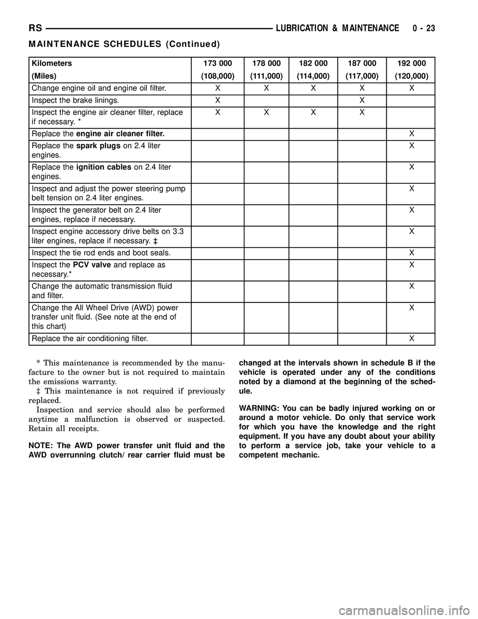
Kilometers 173 000 178 000 182 000 187 000 192 000
(Miles) (108,000) (111,000) (114,000) (117,000) (120,000)
Change engine oil and engine oil filter. X X X X X
Inspect the brake linings. X X
Inspect the engine air cleaner filter, replace
if necessary. *XXXX
Replace theengine air cleaner filter.X
Replace thespark plugson 2.4 liter
engines.X
Replace theignition cableson 2.4 liter
engines.X
Inspect and adjust the power steering pump
belt tension on 2.4 liter engines.X
Inspect the generator belt on 2.4 liter
engines, replace if necessary.X
Inspect engine accessory drive belts on 3.3
liter engines, replace if necessary. ³X
Inspect the tie rod ends and boot seals. X
Inspect thePCV valveand replace as
necessary.*X
Change the automatic transmission fluid
and filter.X
Change the All Wheel Drive (AWD) power
transfer unit fluid. (See note at the end of
this chart)X
Replace the air conditioning filter.X
* This maintenance is recommended by the manu-
facture to the owner but is not required to maintain
the emissions warranty.
³ This maintenance is not required if previously
replaced.
Inspection and service should also be performed
anytime a malfunction is observed or suspected.
Retain all receipts.
NOTE: The AWD power transfer unit fluid and the
AWD overrunning clutch/ rear carrier fluid must bechanged at the intervals shown in schedule B if the
vehicle is operated under any of the conditions
noted by a diamond at the beginning of the sched-
ule.
WARNING: You can be badly injured working on or
around a motor vehicle. Do only that service work
for which you have the knowledge and the right
equipment. If you have any doubt about your ability
to perform a service job, take your vehicle to a
competent mechanic.
RSLUBRICATION & MAINTENANCE0-23
MAINTENANCE SCHEDULES (Continued)
Page 37 of 2585
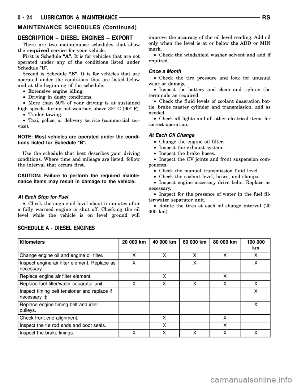
DESCRIPTION ± DIESEL ENGINES ± EXPORT
There are two maintenance schedules that show
therequiredservice for your vehicle.
First is ScheduleªAº. It is for vehicles that are not
operated under any of the conditions listed under
Schedule9B9.
Second is ScheduleªBº. It is for vehicles that are
operated under the conditions that are listed below
and at the beginning of the schedule.
²Extensive engine idling.
²Driving in dusty conditions.
²More than 50% of your driving is at sustained
high speeds during hot weather, above 32É C (90É F).
²Trailer towing.
²Taxi, police, or delivery service (commercial ser-
vice).
NOTE: Most vehicles are operated under the condi-
tions listed for Schedule(B(.
Use the schedule that best describes your driving
conditions. Where time and mileage are listed, follow
the interval that occurs first.
CAUTION: Failure to perform the required mainte-
nance items may result in damage to the vehicle.
At Each Stop for Fuel
²Check the engine oil level about 5 minutes after
a fully warmed engine is shut off. Checking the oil
level while the vehicle is on level ground willimprove the accuracy of the oil level reading. Add oil
only when the level is at or below the ADD or MIN
mark.
²Check the windshield washer solvent and add if
required.
Once a Month
²Check the tire pressure and look for unusual
wear or damage.
²Inspect the battery and clean and tighten the
terminals as required.
²Check the fluid levels of coolant deaeration bot-
tle, brake master cylinder and transmission, add as
needed.
²Check all lights and all other electrical items for
correct operation.
At Each Oil Change
²Change the engine oil filter.
²Inspect the exhaust system.
²Inspect the brake hoses.
²Inspect the CV joints and front suspension com-
ponents.
²Check the manual transmission fluid level.
²Check the coolant level, hoses, and clamps.
²Inspect engine accessory drive belts. Replace as
necessary.
²Inspect for the presence of water in the fuel fil-
ter/water separator unit.
²Rotate the tires at each oil change interval (20
000 km).
SCHEDULE A - DIESEL ENGINES
Kilometers 20 000 km 40 000 km 60 000 km 80 000 km 100 000
km
Change engine oil and engine oil filter.XXXX X
Inspect engine air filter element. Replace as
necessary.XX X
Replace engine air filter element X X
Replace fuel filter/water separator unit.XXXX X
Inspect timing belt tensioner and replace if
necessary. ³X
Replace engine timing belt and idler
pulleys.X
Check front end alignment. X X
Inspect the tie rod ends and boot seals. X X
Inspect the brake linings.XXXX X
0 - 24 LUBRICATION & MAINTENANCERS
MAINTENANCE SCHEDULES (Continued)
Page 566 of 2585

sive, the use of a DRBIIItscan tool and the proper
Diagnostic Procedures manual are recommended for
further testing of the EVIC module and the J1850
PCI data bus circuit.
The EVIC module cannot be repaired, and is avail-
able for service only as a unit. This unit includes the
plastic module and display lens. If any of these com-
ponents is faulty or damaged, the complete EVIC
module must be replaced.
OPERATION
The EVIC has access to both non-switched and
ignition switched sources of battery current so that
some of its features remain operational at any time,
while others may only operate with the ignition
switch in the On position. When the ignition switch
is turned to the On position, the EVIC module VFD
will return to the last function being displayed before
the ignition was turned to the Off position.
The compass/thermometer display is the normal
EVIC display. With the ignition switch in the On
position, momentarily depressing and releasing the
C/T (compass/thermometer) push button switch will
cause the EVIC to return to the compass/thermome-
ter/trip computer display mode from any other mode.
While in the compass/thermometer/trip computer dis-
play mode, momentarily depressing and releasing the
Step push button will step through the available trip
computer display options.
The EVIC trip computer features several functions
that can be reset. The functions that can be reset
are: average fuel economy, trip odometer and elapsed
time. With the ignition switch in the On position and
with one of the functions of the trip computer that
can be reset currently displayed, depressing the
Reset push button twice within three seconds will
perform a global reset, and all of the trip computer
information that can be reset will be reset to zero.
With the ignition switch in the On position and the
function that is to be reset currently displayed,
momentarily depressing and releasing the Reset
push button once will perform a local reset, and only
the value of the displayed function will be reset to
zero. A global or local reset will only occur if the
function currently displayed is a function that can be
reset. The distance to service function can also be
reset using the local reset method, but it will reset
back to the Service Interval distance that is set in
the EVIC programmable features mode. Refer to
ELECTRONIC VEHICLE INFORMATION CEN-
TER PROGRAMMINGin the Standard Procedures
section of this group for more information on setting
the Service Interval.
For more information on the features, control func-
tions and setting procedures for the EVIC module,
see the owner's manual in the vehicle glove box.
DIAGNOSIS AND TESTING - ELECTRONIC
VEHICLE INFORMATION CENTER
Electronic Vehicle Information Center (EVIC) data
is obtained from the Body Control Module (BCM) on
the J1850 Data Bus circuit. The EVIC will display
dashes (- -) for any of the screens it did not receive
the bus messages. The label corresponding to the
missing information will be lit. If no EVIC data is
displayed, check the J1850 Data Bus circuit commu-
nications and the BCM. If the brightness level is
improper check the J1850 Data Bus circuit.
The DRB IIItis recommended for checking the
J1850 Data Bus circuit and the BCM. Perform the
EVIC self diagnosis before replacing the EVIC mod-
ule.
STANDARD PROCEDURE - ELECTRONIC
VEHICLE INFORMATION CENTER
PROGRAMMING
EVIC PROGRAMMING MODE
Some vehicles are equipped with a Electronic Vehi-
cle Information Center (EVIC) equipped overhead
console. The Electronic Vehicle Information Center
(EVIC) provides the vehicle operator with a user
interface, which allows the selection of several
optional customer programmable electronic features
to suit individual preferences. The EVIC must be
placed into its programming mode in order to view or
change the programmable features. To enter the
EVIC programming mode and to view or change the
selected programmable features options, proceed as
follows:
(1) Turn the ignition switch to the On position.
(2) Depress and release the Menu push button.
The first item in the programmable features menu
list will appear in the EVIC display.
(3) Momentarily depress and release the Menu
push button to step through the programmable fea-
tures list. Each programmable feature and its cur-
rently selected option will appear on the EVIC
display in the sequence shown in the Programmable
Features list that follows.
(4) Momentarily depress and release the Step push
button to step through the available options for the
programmable feature being displayed.
(5) The option that last appears in the display
with a programmable feature before exiting the pro-
gramming mode, becomes the newly selected pro-
grammable feature option.
(6) The EVIC exits the programming mode and
returns to its normal operating mode when the C/T
push button is depressed or when the end of the pro-
grammable features menu list is reached, whichever
occurs first.
RSMESSAGE SYSTEMS8M-7
ELECTRONIC VEHICLE INFO CENTER (Continued)
Page 567 of 2585

PROGRAMMABLE FEATURES
NOTE: Tire pressure monitoring (TPM) system infor-
mation is not covered in this section of the service
manual. Refer to the tires/wheels section of this
manual for detailed tire pressure monitoring system
information.
²LANGUAGE?- The options include English,
Francaise, Deutsch, Italiana, or Espanol. The default
is English. All EVIC display nomenclature, including
the trip computer functions, warning messages and
the programmable features appear in the selected
language.
²DISPLAY U.S. OR METRIC?- The options
include U.S. and M. The default is U.S. This feature
toggles the trip computer temperature, fuel economy
and odometer display readings between U.S. and
metric units of measure. It also changes the odome-
ter display in the instrument cluster.
²SERVICE INTV. =- The options include from
1000 to 12000 kilometers in 1000 kilometer incre-
ments (2000 to 7500 miles in 500 mile increments).
The default is 12000 kilometers (7500 miles). The
selected distance becomes the interval at which the
Perform Service warning message will be displayed
by the EVIC. If a new distance is selected, a second
programmable feature appears,RESET SERVICE
DISTANCE?- The options include No and Yes. The
default is Yes. When Yes is selected, the accumulated
distance since the last previous Perform Service
warning message will be reset to zero because the
service interval has been changed. When No is
selected, the distance until the next Perform Service
warning message is reduced by the accumulated dis-
tance since the last previous message.
²USE FACTORY SETTINGS?- The options
include Yes and No. The default is Yes. When yes is
selected all the programmable features will return to
there defaults and the rest of the programmable fea-
tures will not be displayed. If No is selected the rest
of the programmable features will be displayed at
there default values. This feature will automatically
return to the Yes default under two conditions. First,
if no programmable features are changed from there
defaults. Second, if all the programmable features
equal there defaults.
²AUTO DOOR LOCKS?- The options include
Yes and No. The default is Yes. When Yes is selected,
all doors and the liftgate lock automatically when
vehicle speed reaches 25 kilometers-per-hour (15
miles-per-hour). If YES is selected, a second program-
mable feature appears,AUTO UNLOCK ON EXIT?
- The options again include Yes and No. The default
is No. When Yes is selected, following each Auto Door
Lock event all doors and the liftgate will automati-
cally unlock when the driver door is opened, if thevehicle is stopped and the transmission gear selector
is in Park or Neutral. The Auto Door Unlock event
will only occur once following each Auto Door Lock
event.
²REMOTE UNLOCK- The options include
Driver Door 1st and All Doors. The default is Driver
Door 1st. When Diver Door 1st is selected, only the
driver door unlocks when the Unlock button of the
Remote Keyless Entry (RKE) transmitter is
depressed once. The Unlock button of the RKE trans-
mitter must be depressed twice to unlock all doors.
When All Doors is selected, all doors unlock when the
Unlock button of the RKE transmitter is depressed
once.
²REMOTE LINKED TO MEMORY?- This pro-
grammable feature only applies to vehicles equipped
with the optional memory / heated system. The
options include Yes and No. The default is No. When
Yes is selected, the memory system will recall the
Driver 1 or Driver 2 memory settings assigned to the
RKE transmitter being used to unlock the vehicle.
When No is selected, the memory system will only
recall memory settings when the Driver 1 or Driver 2
push buttons of the memory switch on the driver side
front door trim panel are depressed.
²SOUND HORN ON LOCK?- The options
include Yes and No. The default is No. When Yes is
selected, a short horn chirp will provide an audible
confirmation when the RKE receiver recognizes a
valid Lock signal from an RKE transmitter. When No
is selected, no horn chirp will occur with the RKE
Lock event. This feature may be selected indepen-
dent of theFLASH LIGHTS WITH LOCKS?pro-
grammable feature.
²FLASH LIGHTS WITH LOCKS?- The options
include Yes and No. The default is Yes. When Yes is
selected, a single flash of the hazard warning lamps
will provide an optical confirmation when the RKE
receiver recognizes a valid Lock signal from an RKE
transmitter, and two flashes of the same lamps will
occur when the RKE receiver recognizes a valid
Unlock signal from an RKE transmitter. When No is
selected, no lamp flash will occur with the RKE Lock
or Unlock event. This feature may be selected inde-
pendent of theSOUND HORN ON LOCK?pro-
grammable feature.
²HEADLAMP DELAY =- The options include
Off, 30 Sec, 60 Sec, and 90 Sec. The default is 90 Sec.
When a time interval is selected, the headlamps will
remain on for that length of time when the head-
lamps are turned off after the ignition is turned off,
or if the Auto mode is selected on vehicles with the
Auto Headlamps option. When Off is selected, the
headlamp delay feature is disabled.
²HEADLAMPS ON WITH WIPERS?- This pro-
grammable feature only applies to vehicles equipped
8M - 8 MESSAGE SYSTEMSRS
ELECTRONIC VEHICLE INFO CENTER (Continued)
Page 1294 of 2585

INSTALLATION
(1) Snap the left side of the Integrated Power Mod-
ule (IPM) housing in its mounting bracket and con-
nect the various electrical connectors. Care must be
taken that the Connector Positive Assurance (CPA)
on the five-pin B+ connector is positively engaged to
prevent generating a Diagnostic Trouble Code (DTC).
NOTE: IPM electrical connectors are color coded to
ease location reference.
(2) Being certain no wires are stressed or pinched,
rotate the IPM clock-wise until secured in mounting
bracket. An audible click may be heard.
(3) Install the battery in the vehicle. Refer to the
Battery section for the procedure.
(4) Install the battery thermal guard in the vehi-
cle. Refer to the Battery section for the procedure.
(5)
Connect the negative and positive battery cables.
(6) Using a diagnostic scan tool, check for any
stored diagnostic trouble codes and correct, check
that all vehicle options are operational before return-
ing the vehicle to service.
IOD FUSE
DESCRIPTION
All vehicles are equipped with an Ignition-Off
Draw (IOD) fuse that is removed from its normal
cavity in the Integrated Power Module (IPM) whenthe vehicle is shipped from the factory. Dealer per-
sonnel are to remove the IOD fuse from the storage
location and install it into the IPM fuse cavity
marked IOD as part of the preparation procedures
performed just prior to new vehicle delivery.
The IPM has a molded plastic cover that can be
removed to provide service access to all of the fuses
and relays in the IPM. An integral latch and hinges
are molded into the IPM cover for easy removal. A
fuse layout map is integral to the underside of the
IPM cover to ensure proper fuse and relay identifica-
tion. The IOD fuse is a 20 ampere blade-type mini
fuse and, when removed, it is stored in a fuse cavity
adjacent to the washer fuse within the IPM.
OPERATION
The term ignition-off draw identifies a normal condi-
tion where power is being drained from the battery with
the ignition switch in the Off position. The IOD fuse
feeds the memory and sleep mode functions for some of
the electronic modules in the vehicle as well as various
other accessories that require battery current when the
ignition switch is in the Off position, including the
clock. The only reason the IOD fuse is removed is to
reduce the normal IOD of the vehicle electrical system
during new vehicle transportation and pre-delivery stor-
age to reduce battery depletion, while still allowing
vehicle operation so that the vehicle can be loaded,
unloaded and moved as needed by both vehicle trans-
portation company and dealer personnel.
The IOD fuse is removed from the IPM fuse cavity
when the vehicle is shipped from the assembly plant.
Dealer personnel must install the IOD fuse when the
vehicle is being prepared for delivery in order to
restore full electrical system operation. Once the
vehicle is prepared for delivery, the IOD function of
this fuse becomes transparent and the fuse that has
been assigned the IOD designation becomes only
another Fused B(+) circuit fuse. The IOD fuse serves
no useful purpose to the dealer technician in the ser-
vice or diagnosis of any vehicle system or condition,
other than the same purpose as that of any other
standard circuit protection device.
The IOD fuse can be used by the vehicle owner as
a convenient means of reducing battery depletion
when a vehicle is to be stored for periods not to
exceed about thirty days. However, it must be
remembered that removing the IOD fuse will not
eliminate IOD, but only reduce this normal condition.
If a vehicle will be stored for more than about thirty
days, the battery negative cable should be discon-
nected to eliminate normal IOD; and, the battery
should be tested and recharged at regular intervals
during the vehicle storage period to prevent the bat-
tery from becoming discharged or damaged. Refer to
Battery Systemfor additional service information.
Fig. 3 DISCONNECTING IPM
1 - INTEGRATED POWER MODULE FUSE & RELAY CENTER
RS8W-97 POWER DISTRIBUTION SYSTEM8W-97-3
INTEGRATED POWER MODULE (Continued)