wheel alignment CHRYSLER VOYAGER 2004 User Guide
[x] Cancel search | Manufacturer: CHRYSLER, Model Year: 2004, Model line: VOYAGER, Model: CHRYSLER VOYAGER 2004Pages: 2585, PDF Size: 62.54 MB
Page 96 of 2585
required adjustment of camber and caster after the
vehicle is built or when servicing the suspension
components. Thus, when performing a wheel align-
ment, caster and camber are not normally considered
adjustable angles. Camber and caster should be
checked to ensure they meet vehicle specifications.
If front camber is found not to meet alignment
specifications, it can be adjusted using an available
camber adjustment bolt package. Before installing a
camber adjustment bolt package on a vehicle found
to be outside the specifications, inspect the suspen-
sion components for any signs of damage or bending.
CAUTION: Do not attempt to adjust the vehicles
wheel alignment by heating, bending or by perform-
ing any other modification to the vehicle's front
suspension components or body.
If camber readings are not within specifications,
use the following procedure to install the front cam-
ber adjustment bolt package and then adjust front
camber.
CAMBER ADJUSTMENT BOLT PACKAGE INSTALLATION
The camber adjustment bolt package contains 2
flange bolts, 2 cam bolts, 2 dog bone washers, and 4
nuts. This package services both sides of the vehicle.
Use the package to attach the strut clevis bracket to
the steering knuckle after the strut clevis bracket
has been modified. To install and adjust the camber
adjustment bolt package, follow the procedure below.
(1) Raise the vehicle until its tires are not support-
ing the weight of the vehicle.
(2) Remove the front tire and wheel assemblies.
CAUTION:
When removing the steering knuckle from
the strut clevis bracket, do not put a strain on the
brake flex hose. Also, do not let the weight of the
steering knuckle assembly be supported by the
brake flex hose when removed from the strut assem-
bly. If necessary use a wire hanger to support the
steering knuckle assembly or if required remove the
brake flex hose from the caliper assembly.
CAUTION: The knuckle to strut assembly attaching
bolt shanks are serrated and must not be turned
during removal. Remove the nuts while holding the
bolts stationary.
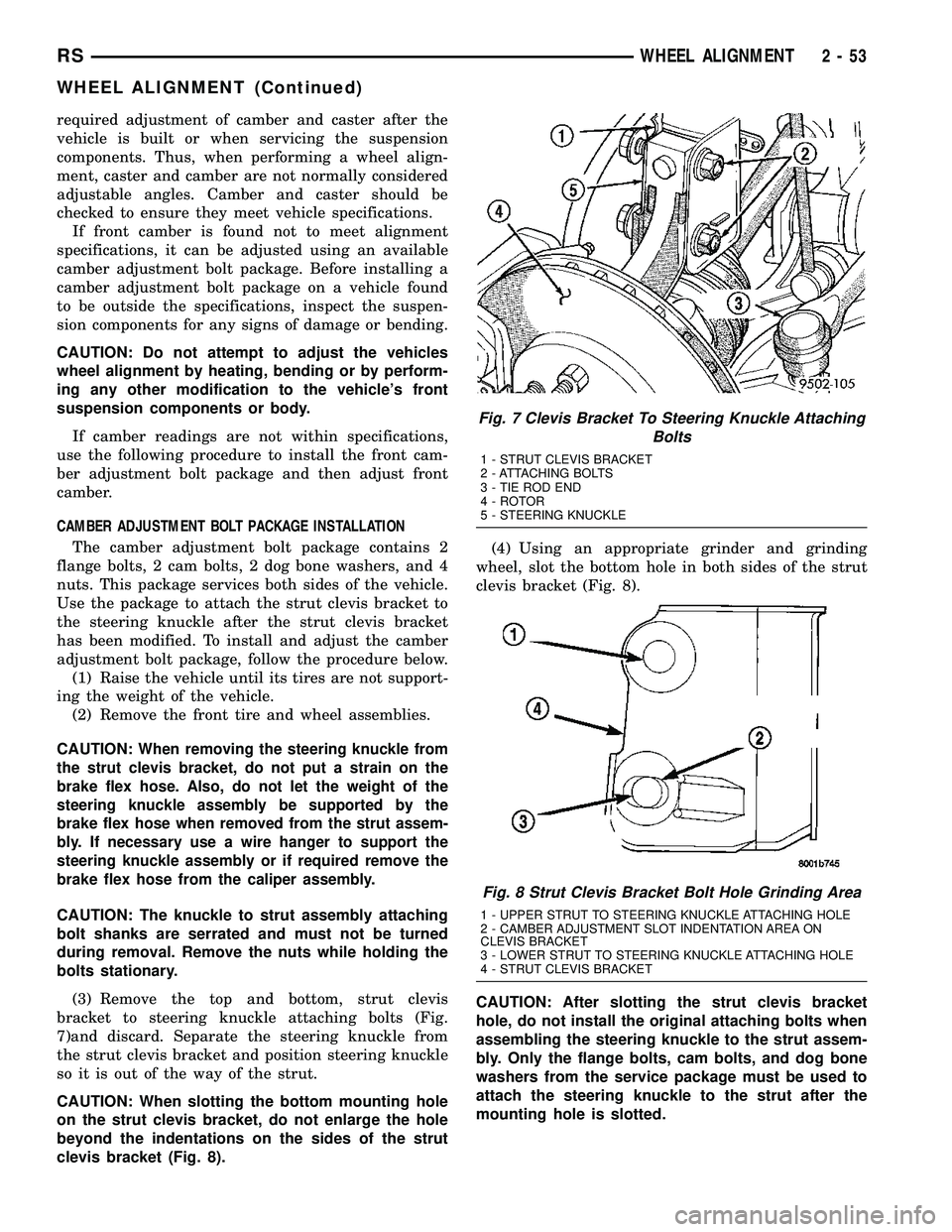
(3) Remove the top and bottom, strut clevis
bracket to steering knuckle attaching bolts (Fig.
7)and discard. Separate the steering knuckle from
the strut clevis bracket and position steering knuckle
so it is out of the way of the strut.
CAUTION: When slotting the bottom mounting hole
on the strut clevis bracket, do not enlarge the hole
beyond the indentations on the sides of the strut
clevis bracket (Fig. 8).(4) Using an appropriate grinder and grinding
wheel, slot the bottom hole in both sides of the strut
clevis bracket (Fig. 8).
CAUTION: After slotting the strut clevis bracket
hole, do not install the original attaching bolts when
assembling the steering knuckle to the strut assem-
bly. Only the flange bolts, cam bolts, and dog bone
washers from the service package must be used to
attach the steering knuckle to the strut after the
mounting hole is slotted.
Fig. 7 Clevis Bracket To Steering Knuckle Attaching
Bolts
1 - STRUT CLEVIS BRACKET
2 - ATTACHING BOLTS
3 - TIE ROD END
4 - ROTOR
5 - STEERING KNUCKLE
Fig. 8 Strut Clevis Bracket Bolt Hole Grinding Area
1 - UPPER STRUT TO STEERING KNUCKLE ATTACHING HOLE
2 - CAMBER ADJUSTMENT SLOT INDENTATION AREA ON
CLEVIS BRACKET
3 - LOWER STRUT TO STEERING KNUCKLE ATTACHING HOLE
4 - STRUT CLEVIS BRACKET
RSWHEEL ALIGNMENT2-53
WHEEL ALIGNMENT (Continued)
Page 97 of 2585

NOTE: The strut clevis-to-knuckle bolts are installed
differently on each side of the vehicle. Left-hand-
side bolts are installed from vehicle rear to front
(Fig. 9). Right-hand-side bolts are installed from
vehicle front to rear.
(5) Position the knuckle back into the strut clevis
bracket. Using the direction indicated in the above
note, install a flanged bolt from the service package
into the upper mounting hole. Using the direction
indicated in the above note, install a cam bolt into
the bottom mounting hole (Fig. 9).
(6) Install a dog bone washer on the steering
knuckle to strut clevis bracket attaching bolts, then
install the nuts onto the bolts from the service pack-
age (Fig. 10). Tighten the bolts just enough to hold
the steering knuckle in position when adjusting cam-
ber, while still allowing the steering knuckle to move
in clevis bracket.
(7) Repeat the procedure to the other side strut
clevis bracket.
(8) Reinstall both front tire and wheel assemblies
and tighten to specifications.
(9) Lower the vehicle. Jounce the front and rear of
vehicle an equal amount of times.
(10) Adjust the front camber to the preferred set-
ting by rotating the lower eccentric cam bolt against
the cam stop areas on the strut clevis bracket (Fig.
11). When camber is set, tighten the upper strut cle-
vis bracket bolt and lower cam bolt. Again jounce
front and rear of vehicle an equal amount of times
and verify front camber setting. Torque both front
strut to steering knuckle attaching bolts to 81 N´m
(60 ft. lbs.) plus an additional 1/4 (90É) turn after the
required torque is met.(11) If toe readings obtained are not within the
required specification range, adjust toe to meet the
preferred specification setting. Toe is adjustable
using the following procedure.
TOE
(1) Center the steering wheel and lock in place
using a steering wheel clamp.
CAUTION: Do not twist front inner tie rod to steer-
ing gear rubber boots during front wheel Toe
adjustment.
(2) Loosen front inner to outer tie rod end jam
nuts (Fig. 12). Grasp inner tie rods at serrations and
Fig. 9 Package Bolts Correctly Installed
1 - STEERING KNUCKLE
2 - FLANGED BOLT IN TOP HOLE
3 - CAM BOLT IN BOTTOM HOLE
4 - STRUT CLEVIS BRACKET
Fig. 10 Dog Bone Washer And Nuts Installed
1 - STEERING KNUCKLE
2 - DOG BONE WASHER
3 - STRUT CLEVIS BRACKET
4 - ATTACHING NUTS
Fig. 11 Camber Adjustment Cam Bolt
1 - STEERING KNUCKLE
2 - CLEVIS BRACKET CAM STOP AREAS
3 - LOWER ECCENTRIC CAMBER ADJUSTMENT BOLT
2 - 54 WHEEL ALIGNMENTRS
WHEEL ALIGNMENT (Continued)
Page 98 of 2585

rotate inner tie rods of steering gear (Fig. 12) to set
front toe to the preferred toe specification. (Refer to 2
- SUSPENSION/WHEEL ALIGNMENT - SPECIFI-
CATIONS)
(3) Tighten tie rod jam nuts (Fig. 12) to 75 N´m
(55 ft. lbs.) torque.
(4) Adjust steering gear to tie rod boots at the
inner tie rod.
(5) Remove steering wheel clamp.
(6) Remove the alignment equipment.
(7) Road test the vehicle to verify the steering
wheel is straight and the vehicle does not wander or
pull.STANDARD PROCEDURE - CURB HEIGHT
MEASUREMENT
The wheel alignment is to be checked and all align-
ment adjustments made with the vehicle at its
required curb height specification.
Vehicle height is to be checked with the vehicle on
a flat, level surface, preferably a vehicle alignment
rack. The tires are to be inflated to the recommended
pressure. All tires are to be the same size as stan-
dard equipment. Vehicle height is checked with the
fuel tank full of fuel, and no passenger or luggage
compartment load.
Vehicle height is not adjustable. If the measure-
ment is not within specifications, inspect the vehicle
for bent or weak suspension components. Compare
the parts tag on the suspect coil spring(s) to the
parts book and the vehicle sales code, checking for a
match. Once removed from the vehicle, compare the
coil spring height to a correct new or known good coil
spring. The heights should vary if the suspect spring
is weak.
(1) Measure from the inboard edge of the wheel
opening fender lip directly above the wheel center
(spindle), to the floor or alignment rack surface.
(2) When measuring, the maximum left-to-right
differential is not to exceed 12.5 mm (0.5 in.).
(3) Compare the measurements to the specifica-
tions listed in the following Curb Height Specifica-
tions charts.
CURB HEIGHT SPECIFICATIONS
VEHICLE FRONT REAR
CARGO VAN755mm 11mm
29.72 in. 0.43 in795mm 11mm
31.30 in. 0.43 in.
ALL OTHERS755mm 11mm
29.72 in. 0.43 in770mm 11mm
30.31 in. 0.43 in.
Fig. 12 Front Wheel Toe Adjustment
1 - INNER TIE ROD SERRATION
2 - OUTER TIE ROD JAM NUT
3 - OUTER TIE ROD END
4 - INNER TIE ROD
5 - STEERING KNUCKLE
RSWHEEL ALIGNMENT2-55
WHEEL ALIGNMENT (Continued)
Page 99 of 2585
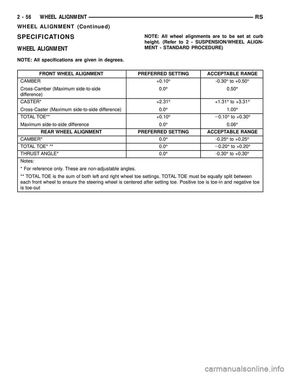
SPECIFICATIONS
WHEEL ALIGNMENT
NOTE: All specifications are given in degrees.NOTE: All wheel alignments are to be set at curb
height. (Refer to 2 - SUSPENSION/WHEEL ALIGN-
MENT - STANDARD PROCEDURE)
FRONT WHEEL ALIGNMENT PREFERRED SETTING ACCEPTABLE RANGE
CAMBER +0.10É -0.30É to +0.50É
Cross-Camber (Maximum side-to-side
difference)0.0É 0.50É
CASTER* +2.31É +1.31É to +3.31É
Cross-Caster (Maximum side-to-side difference) 0.0É 1.00É
TOTAL TOE** +0.10É20.10É to +0.30É
Maximum side-to-side difference 0.0É 0.06É
REAR WHEEL ALIGNMENT PREFERRED SETTING ACCEPTABLE RANGE
CAMBER* 0.0É -0.25É to +0.25É
TOTAL TOE* ** 0.0É20.20É to +0.20É
THRUST ANGLE* 0.0É -0.30É to +0.30É
Notes:
* For reference only. These are non-adjustable angles.
** TOTAL TOE is the sum of both left and right wheel toe settings. TOTAL TOE must be equally split between
each front wheel to ensure the steering wheel is centered after setting toe. Positive toe is toe-in and negative toe
is toe-out
2 - 56 WHEEL ALIGNMENTRS
WHEEL ALIGNMENT (Continued)
Page 101 of 2585

SHUDDER OR VIBRATION DURING ACCELERATION
This problem could be a result of:
²A worn or damaged half shaft inner tripod joint.
²A sticking tripod joint spider assembly (inner tri-
pod joint only).
²Improper wheel alignment. (Refer to 2 - SUS-
PENSION/WHEEL ALIGNMENT - STANDARD
PROCEDURE)
VIBRATION AT HIGHWAY SPEEDS
This problem could be a result of:
²Foreign material (mud, etc.) packed on the back-
side of the wheel(s).
²Out of balance tires or wheels. (Refer to 22 -
TIRES/WHEELS - STANDARD PROCEDURE)
²Improper tire and/or wheel runout. (Refer to 22 -
TIRES/WHEELS - DIAGNOSIS AND TESTING)
REMOVAL
(1) Raise vehicle.
(2) Remove the cotter pin and nut lock (Fig. 2)
from the end of the half shaft.
(3) Remove the wheel and tire assembly from the
vehicle. (Refer to 22 - TIRES/WHEELS - REMOVAL)
(4) Remove the wave washer (Fig. 3) from the end
of the half shaft.(5) With the vehicle's brakes applied to keep hub
from turning,loosen and removethe half shaft
nut.
(6) Remove the two front disc brake caliper
adapter to steering knuckle attaching bolts (Fig. 4).
Fig. 1 Unequal Length Half Shaft System
1 - STUB AXLE 8 - OUTER C/V JOINT
2 - OUTER C/V JOINT 9 - RIGHT HALFSHAFT
3 - OUTER C/V JOINT BOOT 10 - INNER TRIPOD JOINT BOOT
4 - TUNED RUBBER DAMPER WEIGHT 11 - INNER TRIPOD JOINT
5 - INTERCONNECTING SHAFT 12 - INNER TRIPOD JOINT
6 - OUTER C/V JOINT BOOT 13 - INNER TRIPOD JOINT BOOT
7 - STUB AXLE 14 - INTERCONNECTING SHAFT LEFT HALFSHAFT
Fig. 2 Half Shaft Retaining Nut
1 - HUB/BEARING
2 - NUT LOCK
3 - COTTER PIN
4 - STUB AXLE
3 - 2 HALF SHAFT - FRONTRS
HALF SHAFT - FRONT (Continued)
Page 112 of 2585

HALF SHAFT - REAR
TABLE OF CONTENTS
page page
HALF SHAFT - REAR
DESCRIPTION.........................13
DIAGNOSIS AND TESTING - HALF SHAFT....13
REMOVAL.............................13
INSTALLATION.........................14SPECIFICATIONS - HALF SHAFT - FRONT . . . 15
CV BOOT - INNER/OUTER
REMOVAL.............................15
INSTALLATION.........................17
HALF SHAFT - REAR
DESCRIPTION
The inner and outer joints of both half shaft
assemblies are tripod joints. The tripod joints are
true constant velocity (CV) joint assemblies, which
allow for the changes in half shaft length through
the jounce and rebound travel of the rear suspension.
On vehicles equipped with ABS brakes, the outer
CV joint is equipped with a tone wheel used to deter-
mine vehicle speed for ABS brake operation.
The inner tripod joint of both half shafts is bolted
rear differential assembly's output flanges. The outer
CV joint has a stub shaft that is splined into the
wheel hub and retained by a steel hub nut.
DIAGNOSIS AND TESTING - HALF SHAFT
VEHICLE INSPECTION
(1) Check for grease in the vicinity of the inboard
tripod joint and outboard CV joint; this is a sign of
inner or outer joint seal boot or seal boot clamp dam-
age.
NOISE AND/OR VIBRATION IN TURNS
A clicking noise and/or a vibration in turns could
be caused by one of the following conditions:
²Damaged outer CV or inner tripod joint seal
boot or seal boot clamps. This will result in the loss
and/or contamination of the joint grease, resulting in
inadequate lubrication of the joint.
²Noise may also be caused by another component
of the vehicle coming in contact with the half shafts.
CLUNKING NOISE DURING ACCELERATION
This noise may be a result of one of the following
conditions:
²A torn seal boot on the inner or outer joint of the
half shaft assembly.
²A loose or missing clamp on the inner or outer
joint of the half shaft assembly.
²A damaged or worn half shaft CV joint.
SHUDDER OR VIBRATION DURING ACCELERATION
This problem could be a result of:
²A worn or damaged half shaft inner tripod joint.
²A sticking tripod joint spider assembly (inner tri-
pod joint only).
²Improper wheel alignment. (Refer to 2 - SUS-
PENSION/WHEEL ALIGNMENT - STANDARD
PROCEDURE)
VIBRATION AT HIGHWAY SPEEDS
This problem could be a result of:
²Foreign material (mud, etc.) packed on the back-
side of the wheel(s).
²Out of balance tires or wheels. (Refer to 22 -
TIRES/WHEELS - STANDARD PROCEDURE)
²Improper tire and/or wheel runout. (Refer to 22 -
TIRES/WHEELS - DIAGNOSIS AND TESTING)
REMOVAL
(1) Lift vehicle on hoist so that the wheels hang
freely.
(2) Remove rear wheel.
(3) Remove cotter pin, nut lock, and spring washer
(Fig. 1).
Fig. 1 Cotter Pin, Nut Lock, And Spring Washer
1 - HUB NUT
2 - NUT LOCK
3 - COTTER PIN
4 - SPRING WASHER
RSHALF SHAFT - REAR3-13
Page 169 of 2585
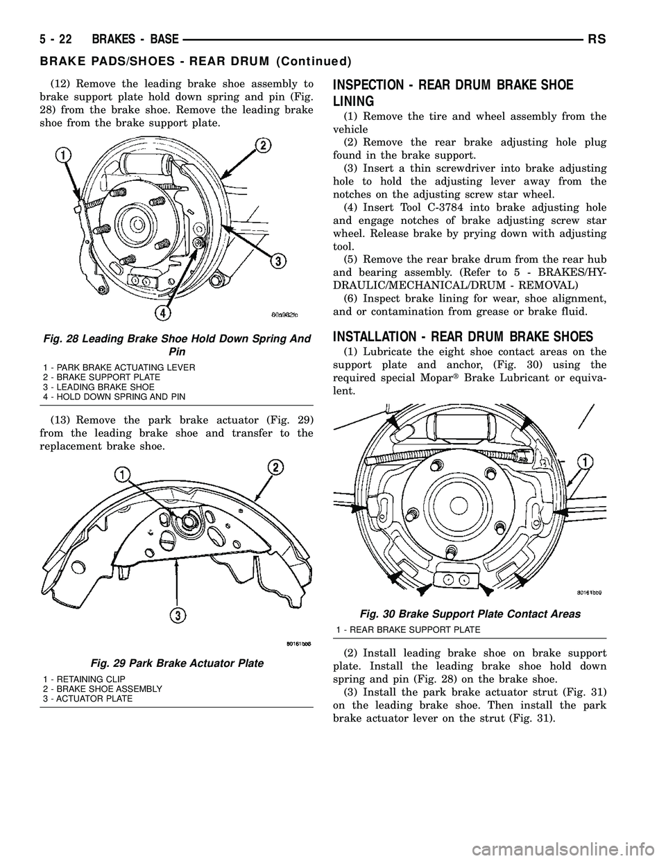
(12) Remove the leading brake shoe assembly to
brake support plate hold down spring and pin (Fig.
28) from the brake shoe. Remove the leading brake
shoe from the brake support plate.
(13) Remove the park brake actuator (Fig. 29)
from the leading brake shoe and transfer to the
replacement brake shoe.INSPECTION - REAR DRUM BRAKE SHOE
LINING
(1) Remove the tire and wheel assembly from the
vehicle
(2) Remove the rear brake adjusting hole plug
found in the brake support.
(3) Insert a thin screwdriver into brake adjusting
hole to hold the adjusting lever away from the
notches on the adjusting screw star wheel.
(4) Insert Tool C-3784 into brake adjusting hole
and engage notches of brake adjusting screw star
wheel. Release brake by prying down with adjusting
tool.
(5) Remove the rear brake drum from the rear hub
and bearing assembly. (Refer to 5 - BRAKES/HY-
DRAULIC/MECHANICAL/DRUM - REMOVAL)
(6) Inspect brake lining for wear, shoe alignment,
and or contamination from grease or brake fluid.
INSTALLATION - REAR DRUM BRAKE SHOES
(1) Lubricate the eight shoe contact areas on the
support plate and anchor, (Fig. 30) using the
required special MopartBrake Lubricant or equiva-
lent.
(2) Install leading brake shoe on brake support
plate. Install the leading brake shoe hold down
spring and pin (Fig. 28) on the brake shoe.
(3) Install the park brake actuator strut (Fig. 31)
on the leading brake shoe. Then install the park
brake actuator lever on the strut (Fig. 31).
Fig. 28 Leading Brake Shoe Hold Down Spring And
Pin
1 - PARK BRAKE ACTUATING LEVER
2 - BRAKE SUPPORT PLATE
3 - LEADING BRAKE SHOE
4 - HOLD DOWN SPRING AND PIN
Fig. 29 Park Brake Actuator Plate
1 - RETAINING CLIP
2 - BRAKE SHOE ASSEMBLY
3 - ACTUATOR PLATE
Fig. 30 Brake Support Plate Contact Areas
1 - REAR BRAKE SUPPORT PLATE
5 - 22 BRAKES - BASERS
BRAKE PADS/SHOES - REAR DRUM (Continued)
Page 229 of 2585

NOTE: Make sure wheel speed sensor stays clean
and dry as it is installed into the hub and bearing
cap.
(1) If metal sensor retaining clip is not in the neu-
tral installed position on hub and bearing cap, install
from the bottom, if necessary, and push clip upward
until it snaps into position.
(2) Install wheel speed sensor head into rear of
hub and bearing aligning index tab with the notch in
the top of the mounting hole. Push the sensor in
until it snaps into place on the metal retaining clip.
(3) Install secondary (yellow) retaining clip over
wheel speed sensor head and engage the tabs on each
side.
(4) Route sensor cable under leaf spring along rear
of axle. Install speed sensor cable into routing clips
on rear brake flex hose (Fig. 3).
(5) Install cable into metal routing clip and attach
it to the rear axle with mounting bolt (Fig. 3).
Tighten mounting bolt to 16 N´m (140 in. lbs.).
(6) Connect wheel speed sensor cable to vehicle
wiring harness (Fig. 2).Be sure speed sensor
cable connector is fully seated and locked into
vehicle wiring harness connector.
(7) Install speed sensor cable grommet into hole in
floor pan making sure grommet is fully seated into
hole.
(8) Lower vehicle.
(9) Road test vehicle to ensure proper operation of
the base and ABS braking systems.
TONE WHEEL
INSPECTION - TONE WHEEL
NOTE: Rear tone wheels for front-wheel-drive vehi-
cles are sealed within the hub and bearing assem-
bly and cannot be inspected or replaced.
Replacement of the hub and bearing is necessary.
Tone wheels can cause erratic wheel speed sensor
signals. Inspect tone wheels for the following possible
causes.
²missing, chipped, or broken teeth
²contact with the wheel speed sensor
²wheel speed sensor to tone wheel alignment
²wheel speed sensor to tone wheel clearance
²excessive tone wheel runout
²tone wheel loose on its mounting surface
If a front tone wheel is found to need replacement,
the drive shaft must be replaced. No attempt should
be made to replace just the tone wheel. (Refer to 3 -
DIFFERENTIAL & DRIVELINE/HALF SHAFT -
REMOVAL)If a rear tone wheel is found to need replacement
on an all-wheel-drive model, the drive shaft must be
replaced. No attempt should be made to replace just
the tone wheel. (Refer to 3 - DIFFERENTIAL &
DRIVELINE/HALF SHAFT - REMOVAL)
If wheel speed sensor to tone wheel contact is evi-
dent, determine the cause and correct it before
replacing the wheel speed sensor or tone wheel.
Check the gap between the speed sensor head and
the tone wheel to ensure it is within specifications.
(Refer to 5 - BRAKES - ABS/ELECTRICAL - SPEC-
IFICATIONS)
Excessive wheel speed sensor runout can cause
erratic wheel speed sensor signals. Refer to SPECI-
FICATIONS in this section of the service manual for
the maximum allowed tone wheel runout (Refer to 5 -
BRAKES - ABS/ELECTRICAL - SPECIFICATIONS).
If tone wheel runout is excessive, determine if it is
caused by a defect in the driveshaft assembly or hub
and bearing. Replace as necessary.
Tone wheels are pressed onto their mounting sur-
faces and should not rotate independently from the
mounting surface. Replacement of the front drive-
shaft, rear driveshaft (AWD only) or rear hub and
bearing is necessary.
TRACTION CONTROL SWITCH
DIAGNOSIS AND TESTING - TRACTION
CONTROL SWITCH
(1) Remove lower column shroud.
(2) Disconnect traction control switch harness from
column harness below column.
(3) Using an ohmmeter, check for continuity read-
ing between pins. Refer to TRACTION CONTROL
SWITCH CONTINUITY test table and (Fig. 5).
TRACTION CONTROL SWITCH CONTINUITY
SWITCH POSITION CONTINUITY BETWEEN
ACTUATED PINS 1 AND 2
ILLUMINATION PINS 1 AND 3
Fig. 5 TRACTION CONTROL SWITCH CONNECTOR
5 - 82 BRAKES - ABSRS
REAR WHEEL SPEED SENSOR - FWD (Continued)
Page 264 of 2585
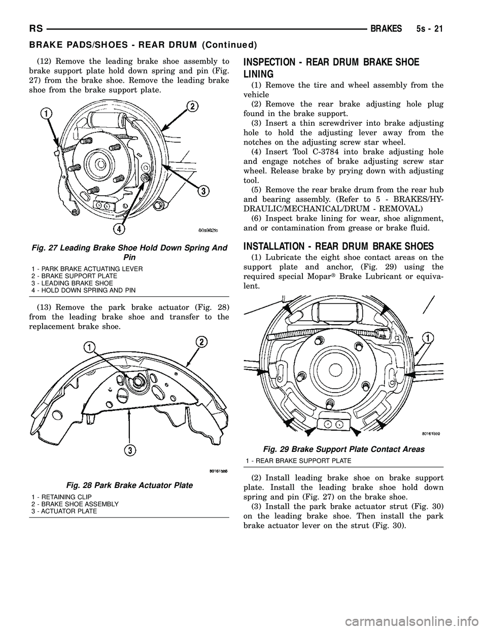
(12) Remove the leading brake shoe assembly to
brake support plate hold down spring and pin (Fig.
27) from the brake shoe. Remove the leading brake
shoe from the brake support plate.
(13) Remove the park brake actuator (Fig. 28)
from the leading brake shoe and transfer to the
replacement brake shoe.INSPECTION - REAR DRUM BRAKE SHOE
LINING
(1) Remove the tire and wheel assembly from the
vehicle (2) Remove the rear brake adjusting hole plug
found in the brake support. (3) Insert a thin screwdriver into brake adjusting
hole to hold the adjusting lever away from the
notches on the adjusting screw star wheel. (4) Insert Tool C-3784 into brake adjusting hole
and engage notches of brake adjusting screw star
wheel. Release brake by prying down with adjusting
tool. (5) Remove the rear brake drum from the rear hub
and bearing assembly. (Refer t o 5 - BRAKES/HY-
DRAULIC/MECHANICAL/DRUM - REMOVAL) (6) Inspect brake lining for wear, shoe alignment,
and or contamination from grease or brake fluid.
INSTALLATION - REAR DRUM BRAKE SHOES
(1) Lubricate the eight shoe contact areas on the
support plate and anchor, (Fig. 29) using the
required special Mopar tBrake Lubricant or equiva-
lent.
(2) Install leading brake shoe on brake support
plate. Install the leading brake shoe hold down
spring and pin (Fig. 27) on the brake shoe. (3) Install the park brake actuator strut (Fig. 30)
on the leading brake shoe. Then install the park
brake actuator lever on the strut (Fig. 30).
Fig. 27 Leading Brake Shoe Hold Down Spring And Pin
1 - PARK BRAKE ACTUATING LEVER
2 - BRAKE SUPPORT PLATE
3 - LEADING BRAKE SHOE
4 - HOLD DOWN SPRING AND PIN
Fig. 28 Park Brake Actuator Plate
1 - RETAINING CLIP
2 - BRAKE SHOE ASSEMBLY
3 - ACTUATOR PLATE
Fig. 29 Brake Support Plate Contact Areas
1 - REAR BRAKE SUPPORT PLATE
RS BRAKES5s-21
BRAKE PADS/SHOES - REAR DRUM (Continued)
Page 322 of 2585
CLUTCH
TABLE OF CONTENTS
page page
CLUTCH
DESCRIPTION..........................1
DIAGNOSIS AND TESTING
DIAGNOSIS AND TESTING - CLUTCH
SYSTEM.............................3
DIAGNOSIS AND TESTING - DRIVE PLATE
MISALIGNMENT.......................6
DIAGNOSIS AND TESTING - CLUTCH
COVER AND DISC RUNOUT..............6
DIAGNOSIS AND TESTING - CLUTCH
CHATTER COMPLAINTS.................6
SPECIAL TOOLS - T850 TRANSAXLE........6
CLUTCH RELEASE LEVER AND BEARING
REMOVAL.............................6
INSTALLATION..........................7
MASTER CYLINDER - RHD
REMOVAL.............................8
INSTALLATION..........................9
MASTER CYLINDER - LHD
REMOVAL.............................9INSTALLATION.........................10
MODULAR CLUTCH ASSY - 2.4L GAS
REMOVAL.............................11
INSTALLATION.........................11
SLAVE CYLINDER
REMOVAL.............................11
INSTALLATION.........................11
CLUTCH DISC AND PRESSURE PLATE - 2.5L TD
REMOVAL.............................11
INSTALLATION.........................12
FLYWHEEL
REMOVAL.............................12
INSTALLATION.........................12
CLUTCH PEDAL INTERLOCK SWITCH
REMOVAL.............................13
INSTALLATION.........................14
CLUTCH PEDAL UPSTOP SWITCH
REMOVAL.............................15
INSTALLATION.........................16
CLUTCH
DESCRIPTION
CLUTCH COMPONENTS
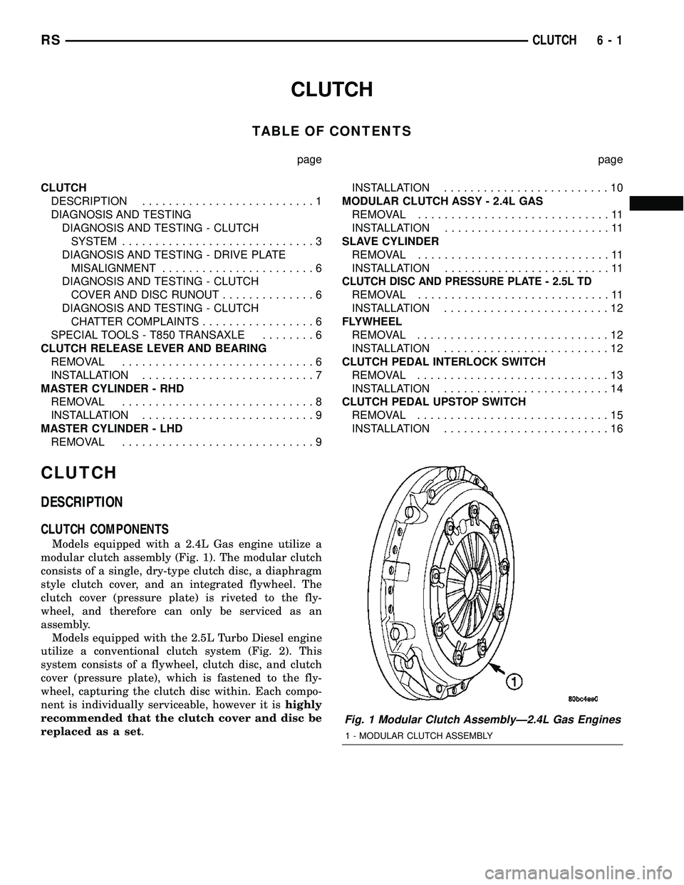
Models equipped with a 2.4L Gas engine utilize a
modular clutch assembly (Fig. 1). The modular clutch
consists of a single, dry-type clutch disc, a diaphragm
style clutch cover, and an integrated flywheel. The
clutch cover (pressure plate) is riveted to the fly-
wheel, and therefore can only be serviced as an
assembly.
Models equipped with the 2.5L Turbo Diesel engine
utilize a conventional clutch system (Fig. 2). This
system consists of a flywheel, clutch disc, and clutch
cover (pressure plate), which is fastened to the fly-
wheel, capturing the clutch disc within. Each compo-
nent is individually serviceable, however it ishighly
recommended that the clutch cover and disc be
replaced as a set.
Fig. 1 Modular Clutch AssemblyÐ2.4L Gas Engines
1 - MODULAR CLUTCH ASSEMBLY
RSCLUTCH6-1